


- sales/support
Google Chat:---
- sales
+86-0755-88291180
- sales01
sales@spotpear.com
- sales02
dragon_manager@163.com
- support
tech-support@spotpear.com
- CEO-Complaints
zhoujie@spotpear.com
- Only Tech-Support
WhatsApp:13246739196
- Purchase/Shipping/Refund
WhatsApp:13424403025
- HOME
- >
- ARTICLES
- >
- LuckFox
- >
- LuckFox Pico
Luckfox Pico RV1103【Tutorial on how to use UART】
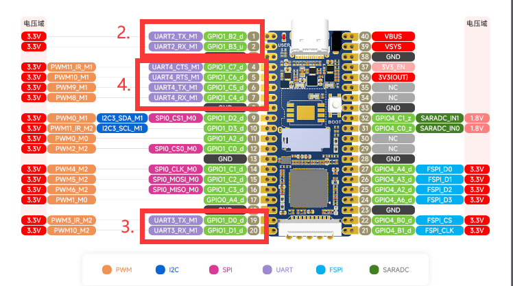
The LuckFox Pico has three serial ports: UART2, UART3, and UART4. Among them, UART2 is the debug port.
The LuckFox Pico Plus has four serial ports: UART2, UART3, UART4, and UART5. Among them, UART2 is the debug port.
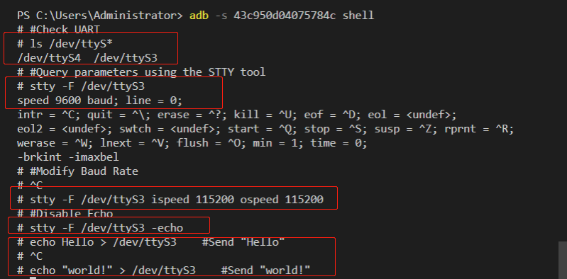
】Performing serial port testing using the GPIO sysfs interface:
1] View serial port:
root@linaro-alip:/home/linaro# ls /dev/ttyS*
/dev/ttyS3 /dev/ttyS4
##The serial port devices here are UART3 and UART4
2] Use the “stty” tool to query the serial port communication parameters:
linaro@linaro-alip:~$ stty -F /dev/ttyS3
speed 9600 baud; line = 0;
-brkint -imaxbel
##The default baud rate is 9600
3] Modify the baud rate, where ispeed is the input rate and ospeed is the output rate:
stty -F /dev/ttyS3 ispeed 115200 ospeed 115200
4] Disable echo:
stty -F /dev/ttyS3 -echo
## Disabling echo refers to the situation where the characters entered in the terminal or serial communication are no longer displayed on the terminal.
5] Operation process screenshot:
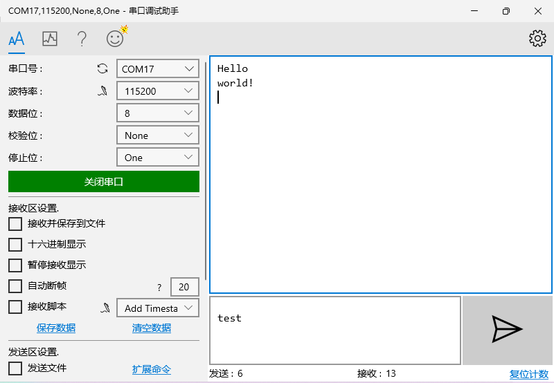
】Communicating with a Windows host:
Connect one end of the serial port module to the computer, and the other end to the physical pins 18 (GND), 19 (UART7_TX), and 20 (UART7_RX) of the LuckFox Pico.
Download and open PuTTY (or any other serial port software), select the serial port, and set the baud rate (default is 9600, please adjust it according to your actual modified value).
Execute the following command on the terminal of the development board to write the strings “Hello” and “world!” to the terminal device file using the echo command:
echo Hello > /dev/ttyS3
echo "world !" > /dev/ttyS3
The serial port debugging assistant on Windows will receive the content:
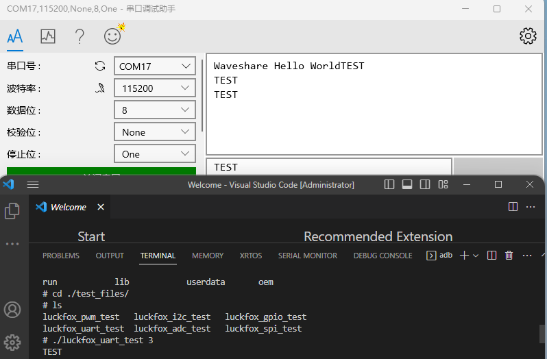
】Test the built-in sample program of the official SDK:
(The following operations need to be performed in the terminal of the Pico development board)
3] Run the test sample program:
chmod 777 ./luckfox_uart_test
## Grant executable permissions to the file
./luckfox_uart_test 3
##The parameter 3 in the example represents UART3.
4] Open the serial communication device to receive data:
TAG:
Raspberry Pi 5 UART
Electronic EYE 0.71inch Round LCD Display Screen For Arduino Raspberry Pi ESP32 Pico STM32
Development Board
Raspberry Pi 10.85 inch e-Paper ink screen display black white 1360×480 For Arduino /Jetson /STM32 /ESP32
Raspberry Pi 21.5inch FHD LCD 1080x1920 Capacitive TouchScreen Display For Raspberry Pi/Jetson Nano/
ESP32 S3 AI 4.3inch (C) Industrial Development Board 4.3 inch TouchScreen Display Sensor CAN I2C RS485 DeepSeek
Raspberry Pi Pico 2 RP2350-Matrix Development Board 8×8 RGB LED Matrix QMI8658 6-Axis Sensor
Horizontal Drag Instructions
Luckfox Pico ST7789
Raspberry Pi Compute Module 4 CM4 PCIe to M.2 NVMe SSD
Orange Pi Zero 3
ESP32 S3 LCD Camera Development Board 2 inch Display QMI8658 Sensor / Battery Port LVGL/HMI For Arduino
Arducam
RM520N GL 5G/4G/3G M.2 Moudle IoT EMBB For LTE-A/NSA/SA And GNSS For DFOTA /VoLTE For Quectel
ESP-IDF download and installation
SpotPear
MPUUART Raspberry Pi 5 PCIe to ISO 2-CH RS485 /2-CH RS232 / USB /UART / TTL
Raspberry-Pi-ESP32-Pico-Display-image-1.83inch-LCD-NV3030B-ADD-NEW-Picture
ESP32-C6 Development Board
JETSON-IO-BASE-A
TAG:
DeepSeek ESP32-S3 Voice Chat Robot
Serial UART Magnetic Encoder Bus Servo TTL ST3235 30KG.CM High Precision Large Torque
Milk V Duo
Raspberry Pi Robot Dog Wavego Pro 12 quadruped ESP32 ESP-NOW color recognition and self-balancing control
EG25-G Mini PCIe SIMCom 4G LTE Cat-4 Global GNSS PCI Express Mini Card
XIAO ESP32 C6 MR60BHA2 60GHz mmWave Breathing and Heartbeat Detection Sensor ESPhome
Raspberry Pi RP2040 LoRa-HF
Raspberry Pi AI Camera 12MP IMX500 RP2040
1.83inch LCD TouchScreen Display 240×284 ST7789P For Arduino /Raspberry Pi /ESP32 /Pico /STM32
Raspberry Pi RP2040 Long-Rang
ESP32 P4 7inch Display TouchScreen
Raspberry Pi 4B PoE
Raspberry Pi Pico ST7789
Cortex-A53
MPS2280 POE Raspberry Pi 5 PCIe M.2 NVMe SSD Pi5 2280 2242 2230
SIM8262E M2 3G 4G 5G GNSS Sub-6G PCIe USB3.1 GPIO M.2 LTE-A NSA SA DFOTA VoLTE SIMCOM
PI5
Luckfox Lyra Pi RK3506
UGV Beast PT AI 4G 5G OpenCV Robot Car MediaPipe Raspberry Pi4B Pi5
Raspberry Pi 0.96inch OLED