- sales/support
Google Chat: zj734465502@gmail.com
- sales
+86-0755-88291180
- sales01
sales01@spotpear.com
- sales02
dragon_manager@163.com
- support
services01@spotpear.com
- CEO-Complaints
manager01@spotpear.com
- sales/support
WhatsApp:13246739196
- HOME
- >
- PRODUCTS
- >
- Common Module
- >
- Power
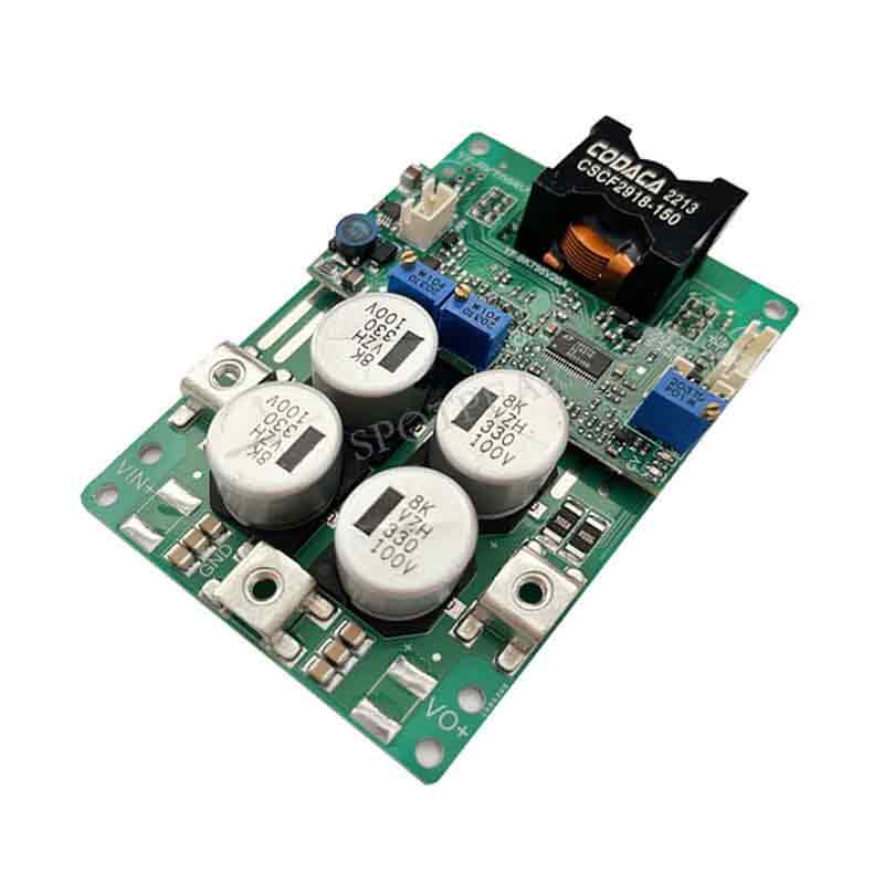
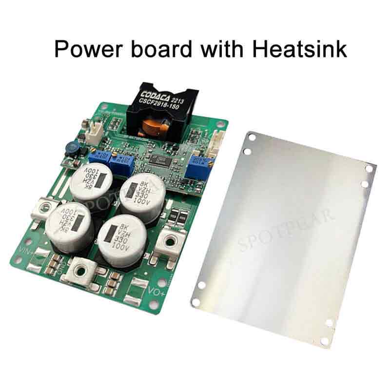
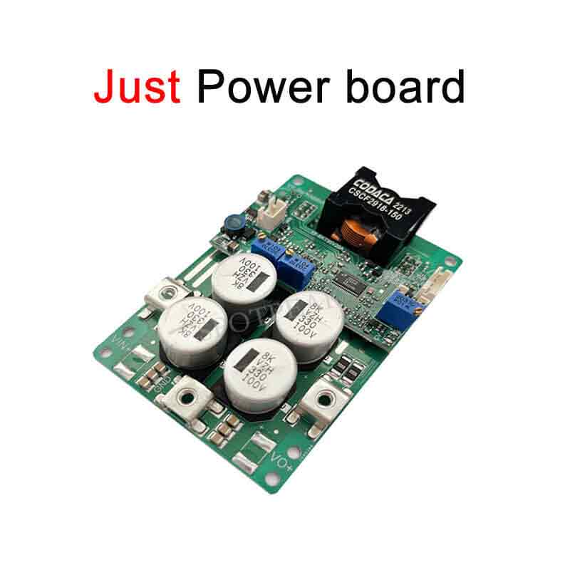
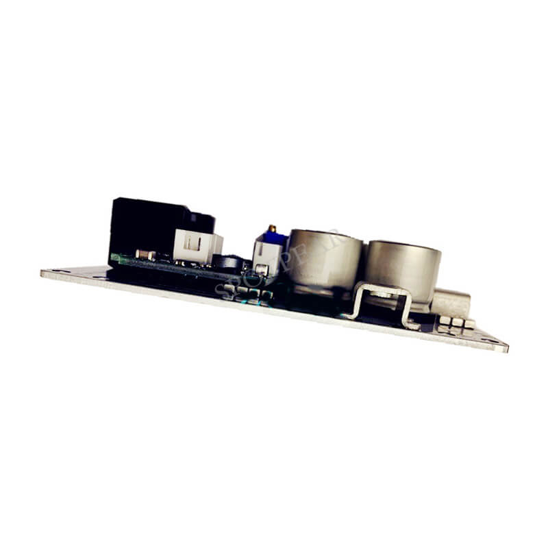
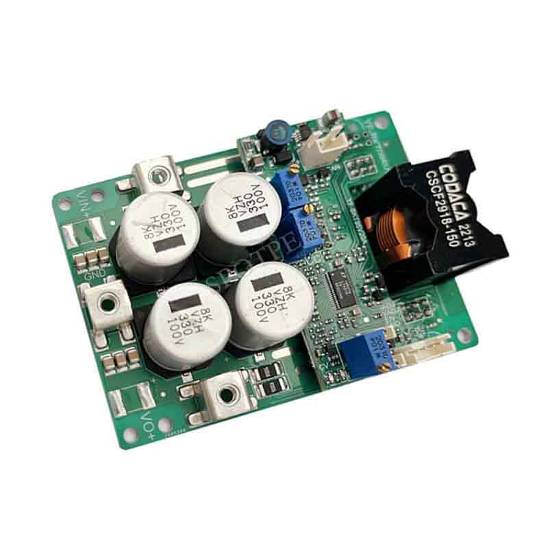
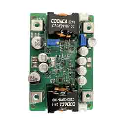
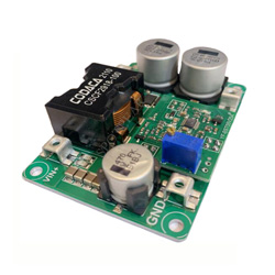
DC DC automatic step up/down power supply 100V adjustable constant current and constant voltage 20A
$75.59
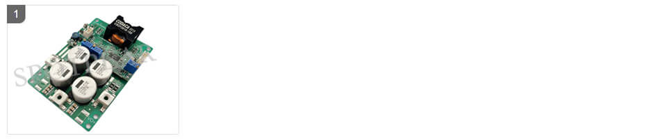
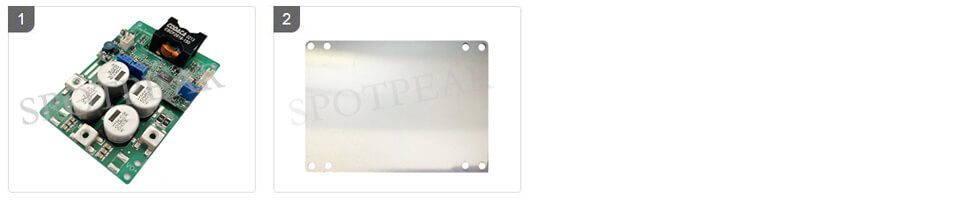
DC-DC automatic step-up/down power supply 100V adjustable constant current and constant voltage 20A
Power Module Recommend

【Note】
[] Do not use a laboratory adjustable power supply with 3A output to test this power supply.
[] Do not test the current-limited power supply using the CC mode of an electronic load.
[] The adjustable range of the output current regulation means that under the condition of sufficient input power, if the output voltage of the power supply is set to 20V and a 0.4Ω resistor is connected to adjust the CC potentiometer, the output current can only be adjusted within a range from the minimum to the maximum of 50A, and cannot be adjusted to the lowest limit value (except for 0A).
【Features】
[] Non-isolated four-switch synchronous buck-boost
[] Wide input range: DC 12-95V, output DC 1-95V
[] Efficiency >97% (reaching up to 99% in direct-pass mode)
[] Overcurrent protection, self-recovering short circuit protection
[] Remote ON/OFF
[] Over-temperature protection
[] Temperature-controlled fan
[] Constant current indicator, optional voltage and current display
[] Adjustable input voltage for battery and fuel cell compatibility
[] Adjustable input voltage and current
[] External control of input voltage and current (with 20ms delay)
[] Optional adjustable direct-pass mode range
[] Battery charging reverse current protection up to 95V
[] Low static current, fast dynamic response, constant-frequency operation for MEI (Micro-Electromechanical Interface) convenience in predictions
[] Power up to 1000W or above (for input and output >48V)
[] Unless otherwise specified, all tests are conducted at 48V input voltage, purely resistive load, and 25°C ambient temperature.
【Specifications】
[] ABSOLUTE MAXIMUM RATINGS:
[] Input voltage: minimum: -1V, typical: none, maximum: 100V, note: continuous
[] Input voltage: minimum: -1V, typical: none, maximum: 100V
[] Power shutdown interface EN: minimum: -0.7V, typical: none, maximum: 70V
[] External voltage control interface: minimum: 0, typical: none, maximum: 12V
[] External current control interface: minimum: 0, typical: none, maximum: 12V
[] Fan interface current limit: minimum: none, typical: none, maximum: 0.3A
[] Storage temperature: minimum: -45, typical: none, maximum: 125 ℃
[] Aluminum substrate and power pin withstand voltage: minimum: none, typical: 300V, maximum: 500V, note: non isolated type
[] Maximum torque of screw terminals: minimum: none, typical: 0.5N. m, maximum: 1N. m
[] Rotation life of Potentiometer: minimum: none, typical: none, maximum: 200 cycles
[] Recommended parameters:
Input voltage: minimum: 12V, typical: none, maximum: 95V
Input current: minimum: 0, typical: 15A, maximum: 20A
Output voltage: minimum: 3V, typical: none, maximum: 95V
Output current: minimum: 0, typical: 15A, maximum: 20A
[] Input characteristics:
Output voltage range: minimum: 12V, typical:/, maximum: 96.0V
Input undervoltage protection adjustable range: minimum:/, typical: 9V, maximum: 80V, note: adjustable resistance
Undervoltage protection hysteresis value: minimum: 0.06 * Vu, typical: 0.07 * Vu, maximum: 0.08 * Vu Remarks: Vu is the set undervoltage value
Input current range: minimum:/, typical: 18A, maximum: 20A
Input current limit value: minimum: 23.5A, typical: 24A, maximum: 24.5A
No-load input current value: minimum: 3.0mA, typical: 6.0mA, maximum: 12.5mA, remarks: 36V to 72V, DCM
Shutdown current: minimum: 0.05mA, typical: 0.1mA, maximum: 0.3mA, note: complete machine shutdown
Direct mode voltage operating range: minimum: 12V, typical: 48V, maximum: 72V
[] Output characteristics:
Output voltage range: minimum:/, typical:/, maximum: 95.0V
Output current working range: minimum:/, typical: 18A, maximum: 20A
Output current limit: minimum: 2.0A, typical:/, maximum: 20.0A
Output voltage adjustment rate: minimum: -0.4%, typical: -1%, maximum: -3%, remarks: constant voltage on load voltage reduction/Vout
Output voltage ripple noise PK-PK: minimum: 60mV, typical: 80mV, maximum: 550mV, note: 48L 92V/860W is the maximum
Output terminal absorption current: minimum: 0.004mA, typical: 0.15mA, maximum: 0.2mA, note: inflow current in shutdown state
[] Dynamic characteristics:
Load step Vo=48V DCM: minimum: none, typical: 6V, maximum: none Remarks: 10-100% lout
Recovery time: minimum: none, typical: 700us, maximum: none Remarks:<2% Vout
Load step Vo=48V CCM: minimum: none, typical: 2.2V, maximum: none Remarks: 10-100% lout
Recovery time: minimum: none, typical: 600us, maximum: none Remarks:<2% Vout
Load step Vo=72V DCM: minimum: none, typical: 6.2V, maximum: none Remarks: 10-100% lout
Recovery time: minimum: none, typical: 700us, maximum: none Remarks:<2% Vout
Load step Vo=72V CCM: minimum: none, typical: 2.2V, maximum: none Remarks: 10-100% lout
Recovery time: minimum: none, typical: 600us, maximum: none Remarks:<2% Vout
Start time: minimum: none, typical: 15ms, maximum: 18ms
Output voltage overshoot CCM: minimum: none, typical: 750mV, maximum: 800mV Remarks: load 100% -0%
Output voltage overshoot DCM: minimum: none, typical: 1400mV, maximum: 1500mV Remarks: load 100% -0%
[] Conversion efficiency:
48V to 89V (800W): minimum: 97.2%, typical: 97.32%, maximum: 97.5%
60V to 60V (900W): minimum: 97.35%, typical: 97.45%, maximum: 97.5%
48V to 24V (300W): minimum: 96.8%, typical: 97%, maximum: 97.1%
96 drops 48V (750W): minimum: 97.59%, typical: 97.69%, maximum: 97.8%
[] Other features:
Switching frequency: minimum: 195KHz, typical: 200KHz, maximum: 205KHz
Boost pressure difference ratio: minimum: none, typical: 2 times, maximum: 3 times Remarks: Vo/Vin
50% derating (lin) pressure difference ratio: minimum: 3 times, typical: 5 times, maximum: 6 times Remarks: Vo/Vin
Pressure drop ratio: minimum: none, typical: 2 times, maximum: 20 times Remarks: Vo/Vin
EN enable close effective voltage: minimum: 0V, classic: 1.0V, maximum: 1.1V
Vout external control effective voltage: minimum: 0V, classic: none, maximum: 2.1V, note: Potentiometer needs to be counterclockwise to the end
Vout external control falling edge delay: minimum: 20ms, classic: 30ms, maximum: 50ms, note: software or RC provides delay
Lout effective voltage of external control: minimum: 0V, classic: none, maximum: 2.1V, note: Potentiometer needs to be counterclockwise to the end
Lout external control falling edge delay: minimum: 20ms, classic: 30ms, maximum: 50ms, note: software or RC provides delay
Load capacity of external control signal: minimum: 2mA, classic: 3mA, maximum: 5mA, note: Potentiometer needs to be counterclockwise to the end
Fan terminal supply voltage: minimum: 11.5V, classic: 11.7V, maximum: 12.2V, note: Vin > 14V
Fan terminal supply current: minimum: 0.2A, classic: 0.25A, maximum: 0.35, note: no short circuit, Vin>14V
Temperature control fan on value: minimum: none, classic: 50 ℃, maximum: 55 ℃, note: aluminum plate temperature
Over temperature protection value: minimum: none, classic: 85 ℃, maximum: 90 ℃, note: aluminum plate temperature
Power supply operating temperature: minimum: -45 ℃, classic: 25 ℃, maximum: 90 ℃
Main controller operating temperature: minimum: -45 ℃, classic: 125 ℃, maximum: none
Working temperature resistance of Electrolytic capacitor: minimum: none, classic: 105 ℃, maximum: none
Storage temperature: minimum: -20 ℃, classic: 25 ℃, maximum: 85 ℃
Cooling method: Natural heat dissipation within 10W of loss, and air cooling with radiator for losses above 26W. Remarks: 25 ℃ ambient temperature
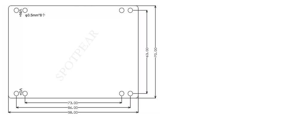
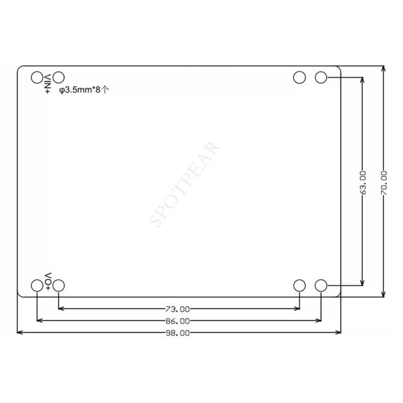
Size: 98 * 70921mm, excluding radiator weight
Note:
1. The voltage adjustment rate is maximum -3% at high output voltage (80V) and current. For demanding requirements, the continuous mode can be selected with an adjustment rate of -1% or less.
2. The direct-pass mode allows for a specific voltage range where the input and output remain directly connected. If the input voltage is below this range, the system operates in step-up mode, while if the input voltage exceeds this range, it operates in step-down mode. For example, if the input range is 20-80V and the direct-pass voltage range is 40-50V, the system operates most efficiently with an input voltage between 40V and 50V. Input voltages below 40V are boosted and stabilized to 40V, while input voltages between 50V and 80V are stepped down and stabilized to 50V.
3. In step-up mode, the output capacitor ripple is bigger, while in step-down mode, the input capacitor ripple is bigger. To reduce heat generation and extend the lifespan, more electrolytic capacitors can be connected in parallel.
4. By default, the discontinuous operating mode allows direct battery charging. For other modes, it is recommended to add an ideal diode to the output.
5. Adjustments may be required for the startup time, especially when the input source has a longer startup time. For example, if the AC adapter takes 50ms to establish full-load voltage output and this power supply has a startup time of 15ms, it may cause abnormal operation.
6. Some parameters may be adjusted based on different applications.
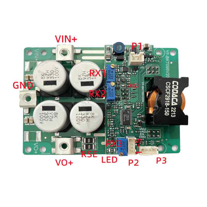
【Instructions】
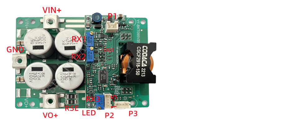
[] Marking on the board: VIN+, function: power input positive pole; Function description: Input+cannot be connected to AC or reversed
[] Marking on the board: GND: Function: Power input/output negative pole, Function description: Common negative pole
[] Marking on the board: VO+: Function: Power output positive pole, Function description: Output positive pole, connected to the positive and negative poles of the battery, not reversed
[] Marking on the board: RX1: Input tracking voltage adjustment, clockwise value increase. If the input power is insufficient and the input voltage drops, it will automatically clamp at the set voltage and reduce the output current. Function description: Suitable for fuel cell, battery board, generator input applications. For example, if the maximum power voltage of the battery board is 36V, input it to 3V and adjust RX1 clockwise until LED 2 is just on. If the forced input is lower than 36V, there will be no output.
[] Marking on the board: RX2: Output current adjustment, clockwise adjustment to increase output current. Function description: 25 turns of Potentiometer corresponds to 0-20A change of output current. If the Potentiometer is damaged or open, the output current limit is 10A
[] Marking on the board: RX3: Output voltage adjustment, clockwise adjustment to increase output voltage. Function description: RX2 adjusts the output voltage value under normal operating mode. If the Potentiometer is damaged or the open circuit output voltage is 48V.
[] Marking on the board: RSE: Output current sampling resistor. Function description: 3m Ω resistor, lout=Vr/0.003. For example, if loaded Vr=0.03V, the current output current is 10A
[] Marking on the board: P1: Temperature control fan 12V/0.3 power supply interface. Function description: Left represents+right represents -, the current should not exceed 0.3A, and there should be no short circuit
[] Marking on the board: P2-1: Control GND. Function description: Connected to the negative pole of the control signal
[] Marking on the board: P2-2: EN enable interface. Function description: This PIN is pulled down to GND power off, with a standby current of uA level. If remote control is required, it is recommended to add optocoupler isolation (line length is susceptible to interference)
[] Marking on the board: P2-3: Output voltage control interface. A rising edge time of more than 20ms must be given. Do not use instantaneous high-frequency control. Function description: The interface controls the input signal voltage of GND from 0 to 2.1V and controls the output voltage to vary from 0-94V. The signal must not be negative, RX2 needs to be counterclockwise to the end before use.
[] Marking on the board: P2-4: Output voltage control interface. A rising edge time of more than 20ms must be given. Do not use instantaneous high-frequency control. Function description: This interface controls the output current of 0-20A for GND input signal voltage 0-2.1V. The signal must not be negative, RX1 needs to be counterclockwise to the end before use.
[] Marking on the board: P3: Voltage and current display meter interface. Function description: optional, used to display the output voltage value
[] Marking on the board: LED: green power indicator light, red fault indicator light. Function description: Output current limiting, short circuit, overvoltage, over temperature red light on, power supply working green indicator light on
[] Marking on the board: LED2: CVIN working indicator light. Function description: If the input voltage is lower than the preset value, the light will turn on. The constant voltage input RX1 should be counterclockwise to the end.
Note:
It is essential to ensure that the input source can provide a sufficiently large current (>35A) for testing this power supply to prevent it from collapsing or being damaged.
The startup time of the input source must be shorter than the startup time of this power supply (for example, when using an adapter as the input), otherwise, there may be difficulties starting with a load.
The input wires connecting the input source to this power supply should not be excessively long, and the wire resistance should not be too high. Otherwise, the power supply may not be able to operate with a load or may even be damaged.
If there is a diode in series between the input source and this power supply, there should be sufficient voltage margin to prevent the power supply from being damaged by instant on/off voltage spikes.
Do not use the CC mode of an electronic load as a load for this power supply. It is recommended to use the CR mode instead. In CC mode, the electronic load absorbs current while the power supply is in constant current mode, which can cause the power supply to collapse.
When adjusting the output voltage, it is necessary to connect a small current resistor load (dummy load) in parallel to ensure the real-time adjustment of the potentiometer. Otherwise, the output voltage changes slowly, and the adjustment may be inaccurate.
【Outline Dimensions】