- sales/support
Google Chat: zj734465502@gmail.com
- sales
+86-0755-88291180
- sales01
sales01@spotpear.com
- sales02
dragon_manager@163.com
- support
services01@spotpear.com
- CEO-Complaints
manager01@spotpear.com
- sales/support
WhatsApp:13246739196
- HOME
- >
- PRODUCTS
- >
- Common Module
- >
- Power
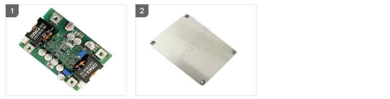
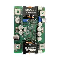
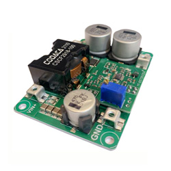
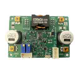
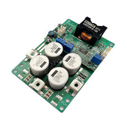
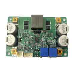
DC Buck Power Module Input 8 32V Output 50A/1V 12V Constant Current Constant Voltage Adjustable
$49.9
DC Buck Power Module Input 8-32V Output Current 50A/1V-12V Constant Current Constant Voltage Adjustable Module
Power Module Recommend
【Note】
[] Do not use a laboratory adjustable power supply with 3A output to test this power supply.
[] Do not test the current-limited power supply using the CC mode of an electronic load.
[] The adjustable range of the output current regulation means that under the condition of sufficient input power, if the output voltage of the power supply is set to 20V and a 0.4Ω resistor is connected to adjust the CC potentiometer, the output current can only be adjusted within a range from the minimum to the maximum of 50A, and cannot be adjusted to the lowest limit value (except for 0A).
【Specifications】
[] Non-isolated synchronous buck (BUCK) power module.
[] Wide input range: DC6-32V, output range: DC0.6-12.2V.
[] Peak efficiency >96%.
[] Overcurrent protection and short circuit protection with self-recovery.
[] Remote ON/OFF.
[] Over-temperature protection, high voltage regulation precision, fast dynamic response.
[] Output current limiting indicator.
[] Adjustable output voltage and current.
[] Low ripple, low static current.
[] Constant-frequency operation for convenient forecasting.
[] Unless otherwise specified, all tests are conducted at 24V input voltage, with purely resistive load, and at 25°C ambient temperature.
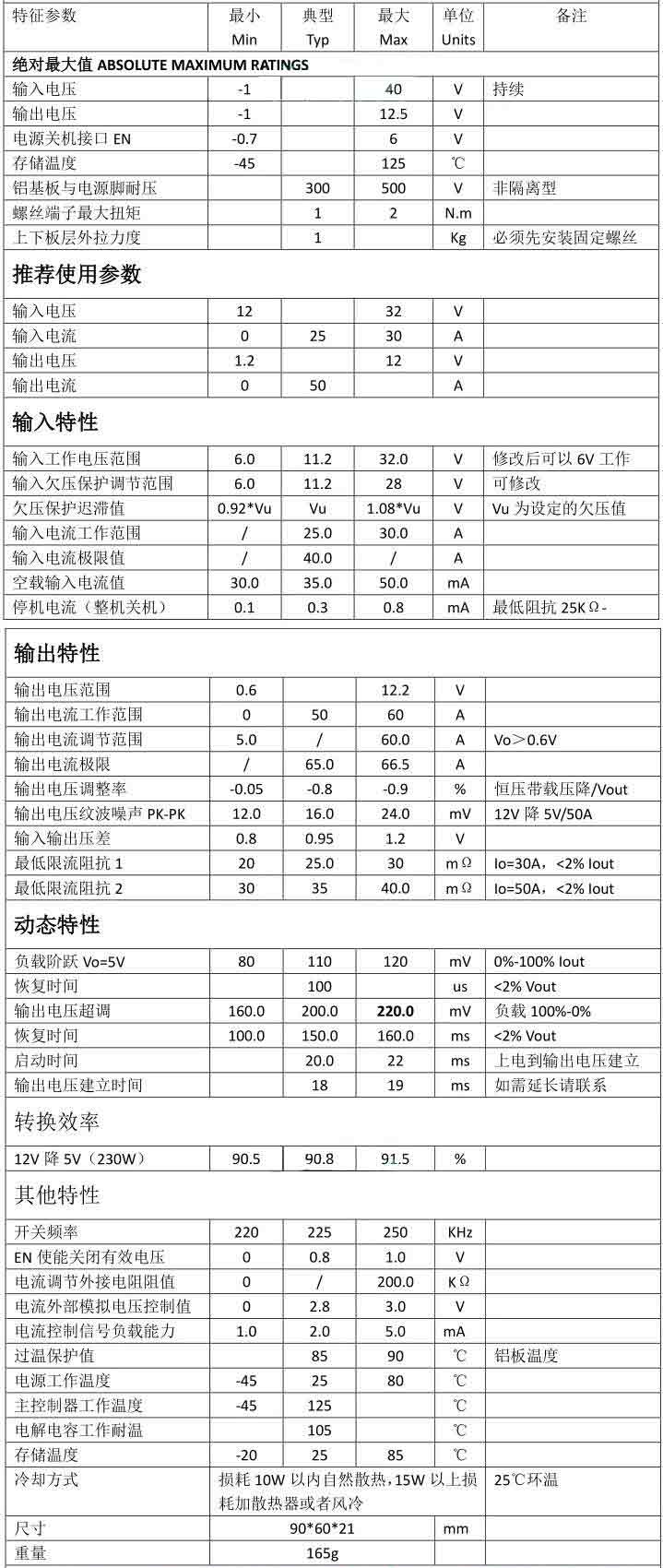
【Parameter】
[] The minimum current adjustment value may be greater than 5A or less than 5A, but it should be ensured that the voltage does not drop below 0.6V after current limiting.
[] Minimum current limiting impedance: When the output voltage is too low, short circuit protection will be activated, which may result in inaccurate current limiting and a deviation in the set current. For example, with a preset current limit of 30A at 5V voltage, when the load resistance is only 0.002Ω, the theoretical voltage is 0.06V. In this case, it is possible for the current to shift to 25A.
[] Adjustment of startup time is required in cases where the input source has a longer startup time. For example, if the AC adapter takes 50ms to establish full-load voltage, and this power supply has a startup time of 15ms, it may result in the AC adapter not starting properly.
[] Some parameters may be adjusted for different applications.
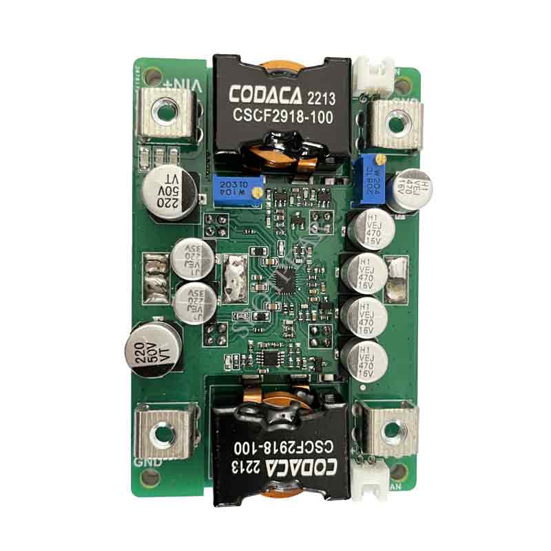
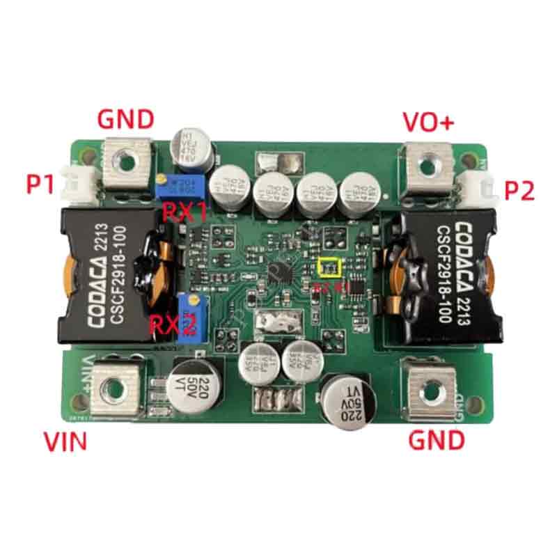
【Instructions】
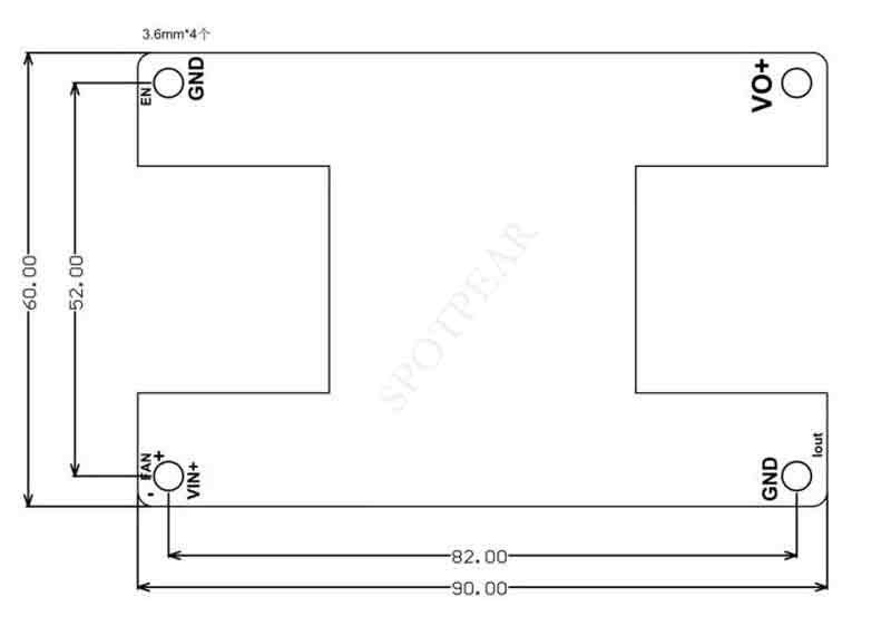
[] VIN+: Power input positive terminal
Function description: INPUT+. Do not connect to AC and do not reverse polarity.
[] GND: Power input/output negative terminal
Function description: Common negative terminal.
[] VO+: Power output positive terminal
Function description: Output positive terminal.
[] RX1: Output voltage adjustment, clockwise increase.
Function description: The potentiometer has 25 turns to adjust the output voltage from 0.6V to 1.2V.
[] RX2: Output current limit adjustment, clockwise increase.
Function description: The potentiometer has 25 turns to adjust the output current limit from 5A to 60A. It can be externally controlled by applying 0-3V to the potentiometer.
[] P1: Power enable interface, short to turn off.
Function description: When the EN pin is shorted to GND (<0.8V), the power supply stops working.
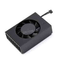
[] P2: Optional 12V temperature-controlled fan interface, do not short circuit, the fan circuit has a fuse.
Function description: Note: Use a fan with the same voltage as the output. For example, if the output is 12V, use a 12V fan; if the output is 5V, use a 5V fan.
[] LED1 (Left): Output current limit indicator
Function description: This LED turns on when the output voltage drops by 10% due to current limiting. It remains off under no load and turns on after over-temperature protection.
[] LED2 (Right): Operation indicator
Function description: This LED turns on when the power supply is powered and in standby mode.
[] R1, R2: Input undervoltage protection setting resistors
Function description: Undervoltage protection is calculated by the formula V = (R1/R2 + 1) * 1.2V. The default value is (85K/10K + 1) * 1.2 = 11.04V.
Note:
[] The input power source must be capable of providing a sufficiently high current (>30A) to prevent the power supply from collapsing or being damaged under any load condition.
[] The startup time of the input source must be shorter than that of the power supply (e.g., when using an adapter as the input). Otherwise, there is a possibility that the power supply may fail to start under load.
[] The input wires connected to the power supply should not be excessively long, and their resistance should not be too high. Otherwise, the power supply may experience oscillations and abnormal behavior.
[] If there is a diode or long wire in series between the input source and the power supply, there should be sufficient voltage margin to ensure that the power supply is not damaged by the transient voltage spikes caused by instant connection and disconnection.
[] Avoid using the Constant Current (CC) mode of an electronic load as the load for this power supply. It is recommended to use the Constant Resistance (CR) mode instead. In CC mode, the load absorbs current while the power supply limits the current. This combination can lead to the collapse of the power supply.
[] It is advisable to connect a small current resistor load (dummy load) when adjusting the output voltage. This ensures real-time adjustment of the output voltage potentiometer and prevents slow voltage changes and inaccurate adjustment values.
[] Please note that these precautions are provided as guidelines to ensure the safe and reliable operation of the power supply.
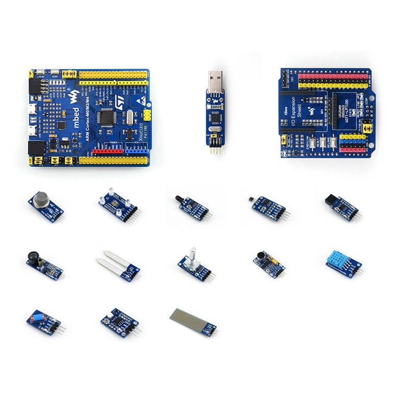
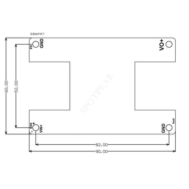
【Outline Dimensions】
【Video】
视频