- sales/support
Google Chat: zj734465502@gmail.com
- sales
+86-0755-88291180
- sales01
sales01@spotpear.com
- sales02
dragon_manager@163.com
- support
services01@spotpear.com
- CEO-Complaints
manager01@spotpear.com
- sales/support
WhatsApp:13246739196
- HOME
- >
- PRODUCTS
- >
- Common Module
- >
- Power
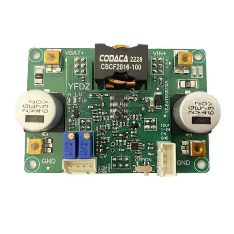
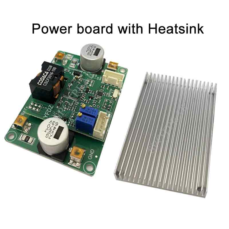
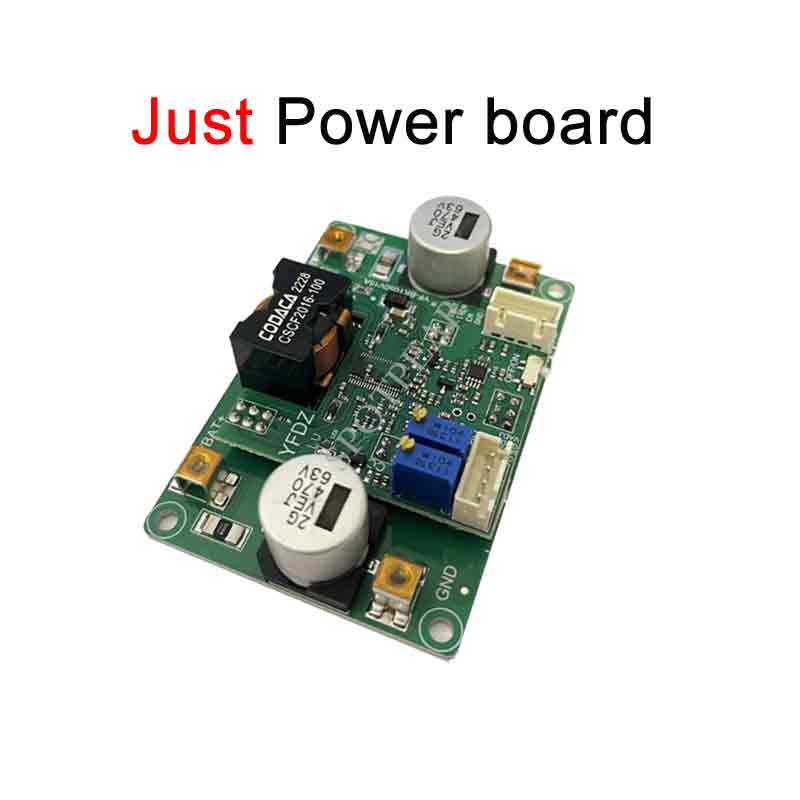
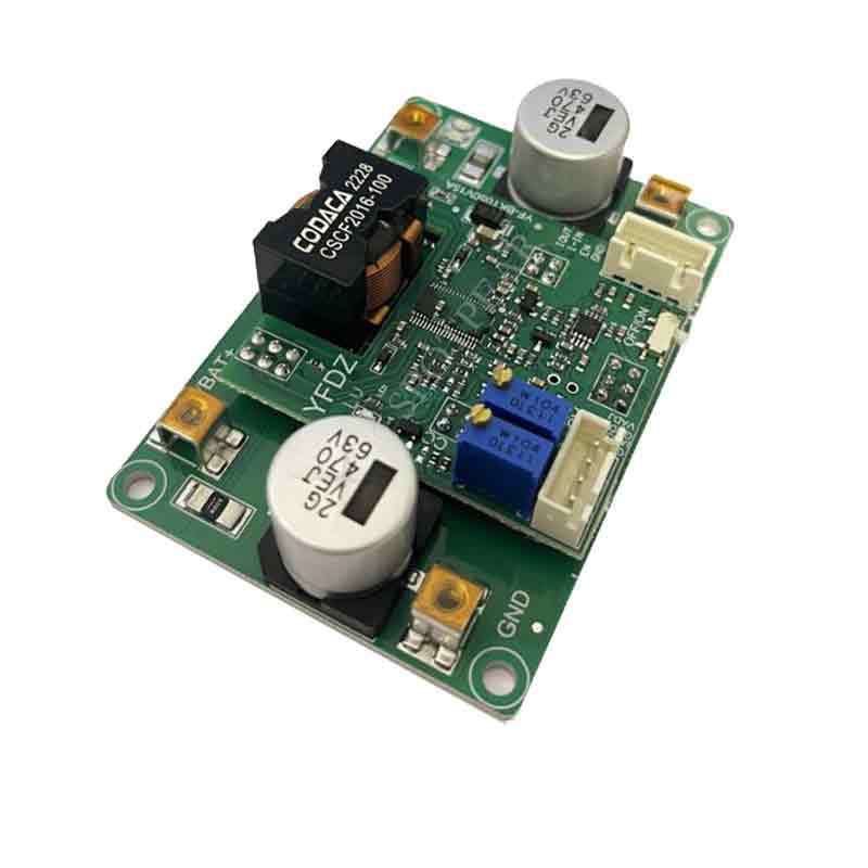
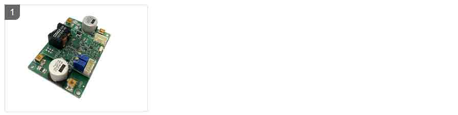
Constant Voltage Constant Current Automatic Step up/down Module LED Constant Current Power
$41.9
Constant Voltage Constant Current Automatic Step-up/down Module LED Constant Current Power Supply Battery Charging 0.5-15A/3-52V
Power Module Recommend

【Note】
[] Do not use a laboratory adjustable power supply with 3A output to test this power supply.
[] Do not test the current-limited power supply using the CC mode of an electronic load.
[] The adjustable range of the output current regulation means that under the condition of sufficient input power, if the output voltage of the power supply is set to 20V and a 0.4Ω resistor is connected to adjust the CC potentiometer, the output current can only be adjusted within a range from the minimum to the maximum of 50A, and cannot be adjusted to the lowest limit value (except for 0A).
【Features】
[] Non-isolated four-switch synchronous buck-boost
[] Wide input range: DC 10-52V, output DC 3-50V
[] Peak efficiency >98.5%
[] Input overvoltage and output short circuit protection with self-recovery, reverse connection protection (input fuse)
[] Over-temperature protection, remote ON/OFF
[] Input and output current signal interfaces
Output voltage and current control interfaces
Accurate and stable output current regulation
Battery charging reverse current protection up to 53V
Constant current charging of supercapacitor at 0V voltage
[] Load indicator lights, complete disconnection of input and output during shutdown
[] Low static current, fast dynamic response, power up to 500W or above (for input and output >36V)
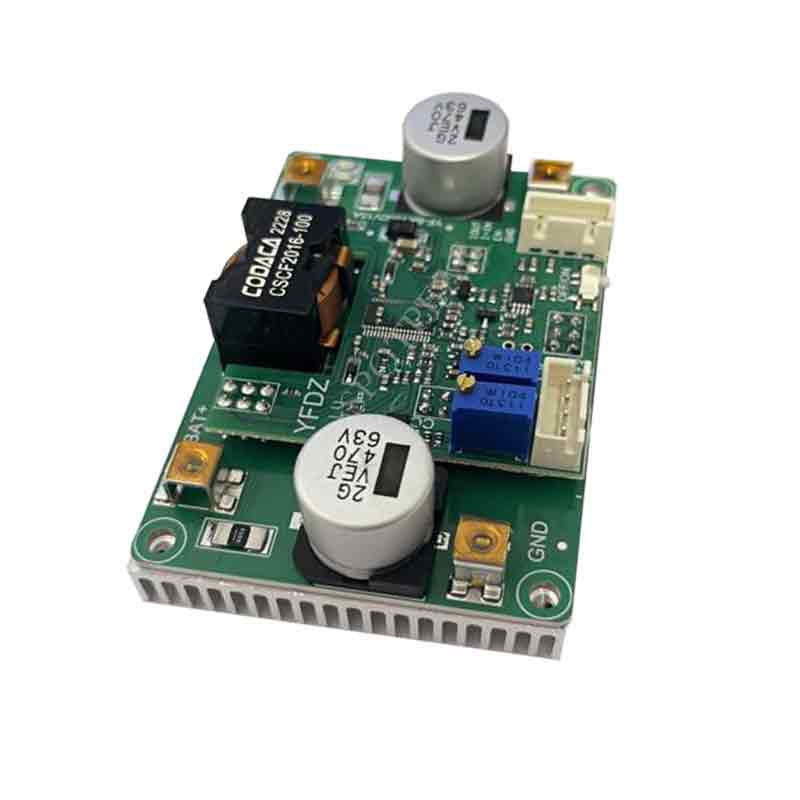
[] Aluminum substrate design with high thermal conductivity, normal operation at 90°C
[] Unless otherwise specified, all tests are conducted at 24V input voltage, purely resistive load, and 25°C ambient temperature.
【Specifications】
[] Absolute maximum value: ABSOLUTE MAXIMUM Ratings:
[] Input voltage: minimum: -1V, typical: none, maximum: 55V Remarks: continuous
[] Output voltage: minimum: -1V, typical: none, maximum: 52V
Storage temperature: minimum: -45 ℃, typical: none, maximum: 125 ℃
[] Aluminum substrate and power pin withstand voltage: minimum: none, typical: 300V, maximum: 500V Remarks: non isolated type
[] Maximum torque of screw terminals: minimum: none, typical: 0.5N.m, maximum: 1 N.m
[] Rotation life of Potentiometer: minimum: none, typical: none, maximum: 200 cycles
[] Recommended parameters:
Input voltage: minimum: 12V, typical: none, maximum: 48V
Input current: minimum:/, typical: 15A, maximum:/
Output voltage: minimum: 3V, typical: none, maximum: 48V
Output current: minimum: 10A, typical: 15A, maximum:/
[] Input characteristics:
Input working voltage range: minimum: 9.2V, typical:/, maximum: 52V
Input undervoltage protection adjustable range: minimum: 5V, typical: 9V, maximum: 48V
Undervoltage protection hysteresis value: minimum: 0.98 * Vu, typical: Vu, maximum: 1.02 * Vu Remarks: Vu is the set undervoltage value
Input current working range: minimum:/, typical: 15A, maximum: 20A
Input current limit value (short time): minimum:/, typical: 22A, maximum:/
No-load input current value: minimum: 0.03mA, typical: 0.06mA, maximum: 0.1mA
[] Output characteristics:
Output voltage range: minimum: 3V, typical:/, maximum: 50V
Output current working range: minimum:/, typical: 15A, maximum: 20A
Output current limit: minimum:/, typical:/, maximum: 20.2A
Load adjustment rate: minimum: -0.3%, typical: -0.62%, maximum: -0.8% Remarks: constant voltage on load voltage drop/Vout
[] Dynamic characteristics:
Load step 24V 24V/15A: minimum: 9.2V, typical: 9.5V, maximum: 9.8V Remarks: 10-100% lout
Recovery time: minimum: none, typical: 1.. 5ms, maximum: none Remarks:<2% Vout
Output voltage overshoot: minimum: 1.1V, typical: 1.3V, maximum: 1.5V Remarks: load 100% -0%
Recovery time: minimum: 160ms, typical: 200ms, maximum: 240ms Remarks:<2% Vout
Start time: minimum: none, typical: 4ms, maximum: 4.5ms Remarks: from power on to output voltage establishment
Output slow start time (0-24V): minimum: none, typical: 1.2ms, maximum: 1.5ms
[] Conversion efficiency:
24V to 48V (300W): minimum: 97.8%, typical: 98%, maximum: 98.1%
48V to 48V (500W): minimum: 98.3%, typical: 98.5%, maximum: 98.7%
48V to 24V (300W): minimum: 96.8%, typical: 97%, maximum: 97.1%
[] Other features:
Switching frequency: minimum: 295KHz, typical: 300KHz, maximum: 305KHz
Recommended boost pressure difference ratio: minimum: none, typical: 2 times, maximum: 3 times Remarks: Vo/Vin
50% derating (lin) pressure difference ratio: minimum: 3 times, typical: 5 times, maximum: 6 times Remarks: Vo/Vin
Over temperature protection value: minimum: none, typical: 90 ℃, maximum: 95 ℃ Remarks: aluminum plate temperature
Power supply operating temperature: minimum: -45 ℃, typical: 25 ℃, maximum: 85 ℃
Main controller operating temperature: minimum: -45 ℃, typical: 125 ℃, maximum: none
Working temperature resistance of Electrolytic capacitor: minimum: none, typical: 105 ℃, maximum: none
Storage temperature: minimum: -20 ℃, typical: 25 ℃, maximum: 85 ℃
Rotating light value: minimum: 0.4A, typical: 0.5A, maximum: 0.52A Remarks: If there is a load, the red light will light up
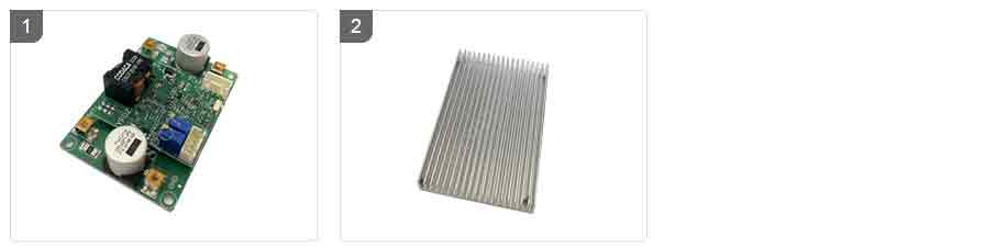
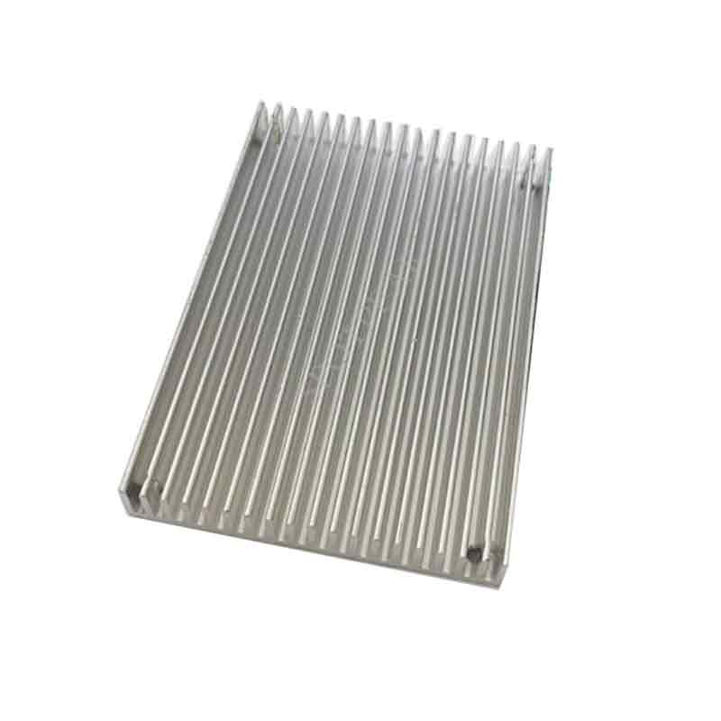
Cooling method: Natural heat dissipation within 6W of loss, heat sink or air cooling for losses above 10W. Remarks: 25 ℃ ambient temperature
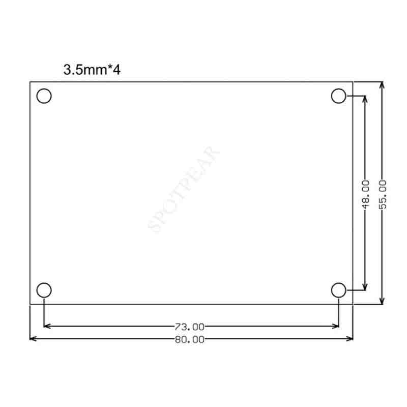
Size: 80 * 55 * 20mm
Weight: 72.0g Remarks: Without radiator weight
[] Note:
1. Boosting the output voltage results in large ripple current in the output capacitor. To reduce capacitor heating and extend its lifespan, electrolytic capacitors can be connected in parallel.
2. Charging the battery is not supported as there is no current limiting capability. The maximum input current is limited to 33A.
3. Adjustments to the output ramp-up time may be necessary in cases where the input source has a longer startup time. For example, if the AC adapter takes 50ms to reach its full load voltage, and this power supply has a startup time of 2ms, it may cause issues if the AC load is unable to start properly. In such cases, it is recommended to start the AC power supply first and then start the DC power supply.
4. It is important to note that the output of the boost power supply cannot be shut off. After under-voltage protection is triggered, the output voltage becomes the same as the input voltage, allowing it to pass through.
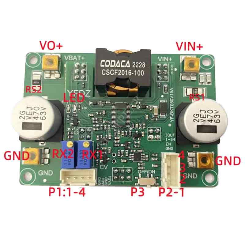
【Instructions】
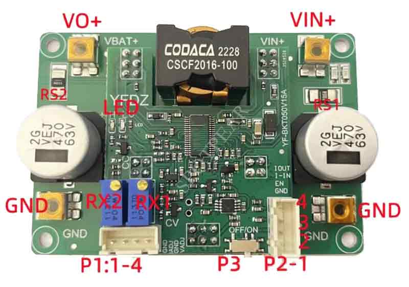
[] Marking on the board: VIN+, function: input positive pole; Function description: Connect the positive pole of the input source, battery, switching power supply, generator, etc
[] Marking on the board: GND, function: public negative electrode; Function description: Input output negative is connected
[] Marking on the board: VO+, function: output positive pole; Function description: Output to battery, load, supercapacitor, and other positive electrodes
[] Marking on the board: RX1, function: output voltage adjustment, clockwise adjustment to increase output voltage; Function description: 25 turns of Potentiometer correspond to the change of control output voltage 0-50V range. Adjust the output voltage during actual testing. With Potentiometer open circuit protection, Potentiometer open circuit output voltage is fixed at 25V
[] Marking on the board: LED - green light, function: charging indicator light; Function description: Output current>0.5A (modifiable) not lit,<0.5A lit
[] Marking on the board: LED - red light, function: load indicator light; Function description: If the output current is greater than 0.5A (adjustable), it will light up, but if it is less than 0.5A, it will not light up. If there is load flashing, it may be due to unstable input and frequent undervoltage, or fluctuations in the load current itself
[] Marking on the board: P1-1 Function: Control signal GND Function description: GND interface for controlling voltage and current
[] Marking on the board: P1-2 Function: Output current control interface (note: the control signal should not change step by step, and it needs to be>30ms up and down) Function description: Reference GND to provide a voltage of 0-1.2V to control the output current to change from 0-20A. The proportion can be modified. For details, please refer to: voltage and current control conditions: the Potentiometer shall not be counterclockwise to the end, and it is recommended to be maximum or removed
[] Marking on the board: P1-3 Function: Control signal GND Function description: GND interface for controlling voltage and current
[] Marking on the board: P1-4 Function: Output voltage control interface (note: the control signal should not change step by step, and it needs to be>30ms at the falling edge) Function description: The interface can control the output voltage change of 50-0V by providing a 0-2.4V voltage signal. See details: voltage and current control conditions: the Potentiometer is centered or counterclockwise to the bottom
[] Marking on the board: P2-1 Function: Control signal GND Function description: GND interface for controlling voltage and current
[] Marking on the board: P2-2 Function: External power enable EN interface Function description: This PIN is connected to GND and the power is turned off, with a standby current level of uA. The PIN voltage is lower than 1.2V, and the power supply does not work. Interference must not be introduced and can only be pulled down
[] Marking on the board: P2-3 Function: Input current signal Function description: Signal voltage Vlin=0.05V * lin, for example, if the input current is 10A, the interface voltage is 0.5V. There is a certain deviation and a very low bias
[] Marking on the board: P2-4 Function: Input current signal Function description: Signal voltage value Viout=0.03V * lo, for example, if the output current is 10A, the interface voltage is 0.3V
[] Marking on the board: P3 Function: Auxiliary test switch Function description: Used for factory testing, limited lifespan, not recommended for frequent use.
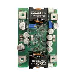
[] Marking on the board: PS1 Function: Input current sampling resistor (modifying the sampling resistor can reduce the maximum input current, and the control resolution will correspondingly increase) Function description: 2512 packaging resistor, current I=Vs/RS. Input RS=2m Ω. For example, if the measured voltage at both ends of the output resistor is 0.03V, the current output current is 10A.
[] Marking on the board: PS2 Function: Output current sampling resistor (modifying the sampling resistor can reduce the maximum output current, and the control resolution will correspondingly increase) Function description: 2512 packaging resistor, current I=Vs/RS. Output Rs=3mR. For example, if the measured voltage at both ends of the output resistor is 0.03V, the current output current is 10A.
[] Note:
1. When testing this power supply, it is important to ensure that the input source can provide a sufficiently high current (>25A) to prevent the power supply from collapsing or even getting damaged, especially during load startup. During hot testing, it is necessary to first connect the negative pole and then the positive pole, and when shutting it down, disconnect the positive pole first.
2. The startup time of the input source must be shorter than that of this power supply (for example, when using an adapter as the input), otherwise, it may not be able to start under load.
3. The input wires connected to this power supply should not be too long (the internal resistance of the wires should not be too high), as this may cause oscillations and abnormal behavior in the power supply.
4. If there is a diode connected in series between the input source and this power supply, the power supply may be damaged due to the surge voltage caused by the momentary on/off connection (line-boost effect).
5. Do not use the constant current (CC) mode of an electronic load as the load for this power supply. It is recommended to use the constant resistance (CR) mode instead. The CC mode absorbs current while the power supply limits it, which can lead to the breakdown of the power supply under constant current conditions.
6. It is recommended to connect a small current resistor load (dummy load) when adjusting the output voltage to ensure real-time adjustment of the output voltage potentiometer. Otherwise, the output voltage may change slowly, and the adjustment value may be inaccurate.
【Outline Dimensions】
【Video】
视频