


- sales/support
Google Chat: zj734465502@gmail.com
- sales
+86-0755-88291180
- sales01
sales01@spotpear.com
- sales02
dragon_manager@163.com
- support
services01@spotpear.com
- CEO-Complaints
manager01@spotpear.com
- sales/support
WhatsApp:13246739196
- HOME
- >
- ARTICLES
- >
- Common Moudle
- >
- UART Module
RS232-485-422-TO-CAN Guide
Resource
Software
External Test Demo
Datasheet
Overview
Introduction
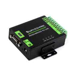
RS232/485/422 TO CAN is an industrial-grade RS232/485/422 to CAN isolated converter. It features built-in power isolation, ADI magnetic coupling isolation, TVS, and other protection circuits, with an industrial guide rail case. RS232/485/422 TO CAN is easy to operate, with zero-delay automatic send/receive conversion. It possesses characteristics such as fast, stable, reliable, and secure communication speeds, making it suitable for various industrial control devices or applications with high communication requirements.
Features
- Adopts SP3232EEN + SP485EEN chips, stable and high-speed communication, with better compatibility.
- Onboard unibody power supply isolation, provides stable isolated voltage and needs no extra power supply for the isolated terminal.
- Onboard unibody digital isolation, allows signal isolation, high reliability, strong anti-interference, and low power consumption.
- Compliant with CAN 2.0B (extended frame) specification, compatible with CAN 2.0A (standard frame) specification; Compliant with ISO 11898-1/2/3 standard.
- CAN baud rate: 10kbps~1000kbps, configurable CAN baud rate.
- High-speed conversion: At a serial port baud rate of 115200 and CAN rate of 250kbps, the CAN sending speed can reach up to 1270 extended frames per second.
- Supports data communication and conversion between RS232/485/422 and CAN interfaces.
- Supports 4 operating modes: transparent conversion, transparent with identifiers conversion, format conversion, and Modbus RTU protocol conversion.
- Onboard TVS (Transient Voltage Suppressor), effectively suppresses surge voltage and transient spike voltage in the circuit, lightningproof & anti-electrostatic.
- Onboard self-recovery fuse and protection diodes, ensure the current/voltage stable outputs, provide over-current/over-voltage proof, and improve shock resistance.
- Onboard 15KV ESD isolation protection and 600W lightningproof & anti-surge protection.
- Onboard 120R terminal resistor on the RS485/RS422 port, configurable by jumper.
- Supports device firmware upgrade via RS232/485/422, more convenient for firmware customization.
- Supports setting operation parameters via configuration software or serial commands, capable of saving settings after powering off.
- Onboard power supply screw terminal, allows 5V~36V DC wide-range input.
- 4 LEDs for indicating the power and transceiver status.
- Industrial grade metal case, supports wall-mount and rail-mount installation, solid and beautiful, easy to install.
Parameters
| Product | Industrial isolated RS232/485/422 TO CAN | |
| Host Interface | CAN | |
| Device Interface | RS232/485/422 | |
| CAN Interface | Baud Rate | 10kbps~1000kbps |
| Direction Control | Hardware automatic control | |
| Resistor | Default 120R | |
| Interface | Screw terminal | |
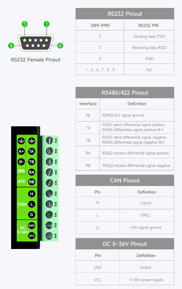
| CAN Interface | A+, B-, GND | |
| RS232/485/422 Interface | Baud Rate | 1200bps ~ 460800bps |
| Direction Control | Hardware automatic control | |
| Resistor | Onboard reserved 120R matching resistor, NC by default, enabled via jumpers | |
| RS232 Interface | DB9 Interface | |
| RS485/422 Interface | Screw terminal | |
| RS485 Interface | A+, B-, GND | |
| RS422 Interface | TA, TB, RA, RB, GND | |
| Protection | Provides 600W of lightning, surge, and 15KV static protection (on-board 120R balancing resistor) | |
| Transmission Mode | Point-to-multipoints (up to 32 nodes, it is recommended to use repeaters for 16 nodes or more) | |
| Button | Press and hold for 1 second | Reset the system |
| Press and hold for 5 seconds | Restore Factory Status | |
| Indicator | PWR | Red power indicator, lights up when voltage is detected |
| RUN | Operation status indicator, normal operation blinks at 1-second intervals | |
| COM | CAN green TX indicator, lights up when the CAN port sends data RS232/485/422 green RX indicator, lights up when RS232/285/422 port receives data | |
| CAN | CAN blue RX indicator, lights up when CAN port receives data RS232/485/422 blue TX indicator, lights up when RS232/485/422 port sends data | |
| Environment | Temperature range | -10℃ ~70℃ |
Interface Introduction
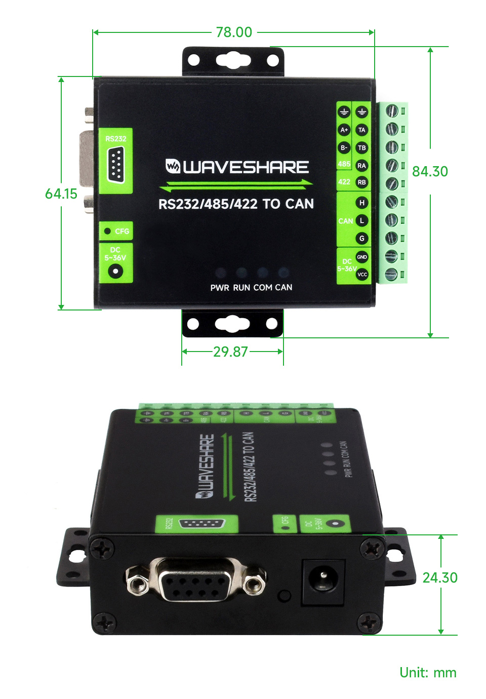
Dimensions
Device Configuration
Use USB TO 4CH Serial Converter (or USB to RS232, USB to RS485 or USB to RS422) for initial configuration. No configuration is performed, and the factory settings are maintained.
Hardware Connection
- Connect USB to RS232/485/422 device (the following shows RS485 interface connection of USB TO 4CH Serial Converter):
RS232/485/422 TO CAN - RS485 USB TO 4CH Serial Converter - Port C RS485 - GND Port C - GND RS485 - A+ Port C - A+ RS485 - B- Port C - B-
Software Operation
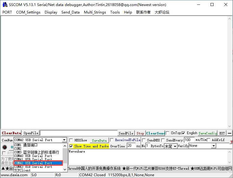
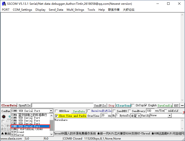
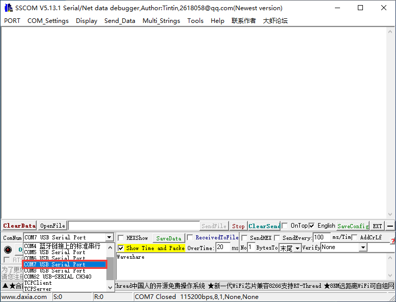
- Open SSCOM, view the COM port used, and perform it with the COM42:
- Open WS-CAN-TOOL
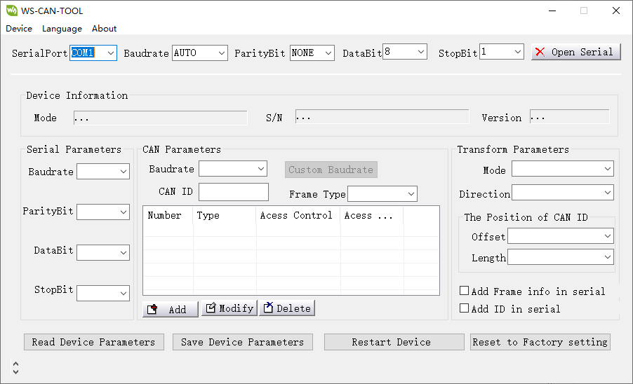
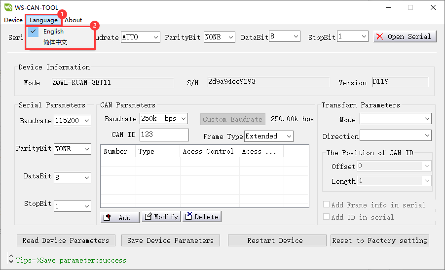
- Select the language:
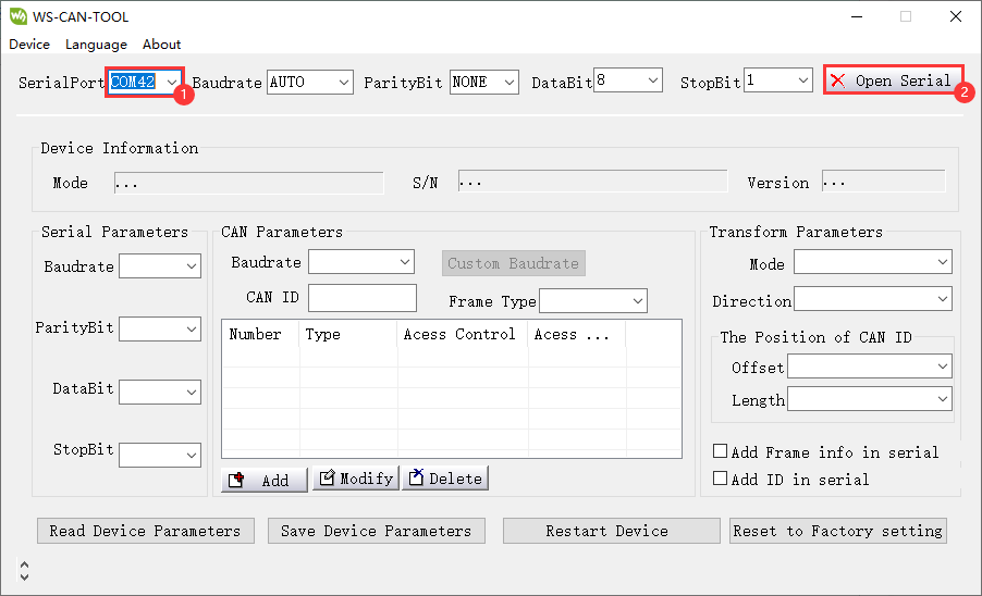
- Select the COM port corresponding to the connected RS232/485/422, and then open the serial port:
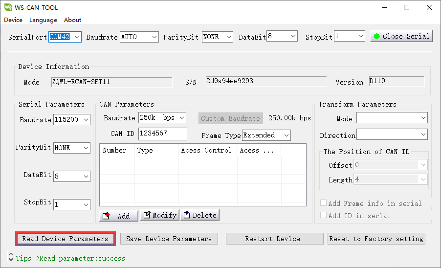
- Click on Read Device Parameters.
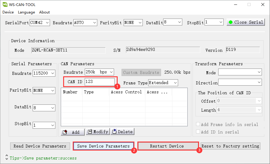
- If you need to modify the device parameters, you can directly modify it and click on "Save Device Parameters", and then click on "Restart Device" (for example, modifying CAN ID):
Module Usage Explanation
Transparent Conversion
*In this mode, the converter promptly sends the received data from one bus to the other bus.
USRT To CAN
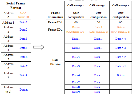
- The entire data of a serial frame is sequentially filled into the data field of a CAN message frame. Upon receiving a frame of data from the serial bus, the converter promptly transmits it to the CAN bus. The converted CAN message frame information (frame type section) and frame ID are pre-configured by the user and remain unchanged throughout the conversion process.
- The format of the data conversion is illustrated in the diagram below.
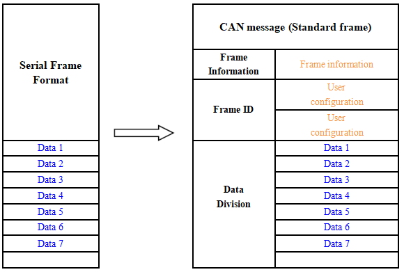
- If the length of the received serial frame is less than or equal to 8 bytes, characters from 1 to n (where "n" is the length of the serial frame) are sequentially filled into positions 1 to n in the data field of the CAN message (as depicted in the illustration where "n" is 7).
If the number of bytes in the serial frame is greater than 8, the processor starts from the first character of the serial frame and fills the first set of 8 characters sequentially into the data field of the CAN message. After transmitting this data onto the CAN bus, it proceeds to convert the remaining serial frame data and fills the CAN message's data field until all the data has been converted.
For example, in the CAN parameter settings, if "Standard Frame" is chosen and the CAN ID is filled with 00000060, note that only the last 11 bits are valid for standard frames. The converted CAN data appears as follows: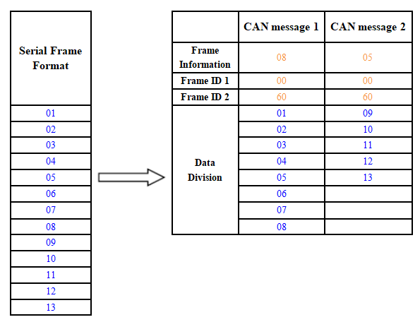
CAN Frame To UART
- For the CAN bus, it promptly sends a frame after receiving a frame.
- When converting, all the data in the CAN message field is converted to the serial frame in order, and the corresponding data format is shown below:
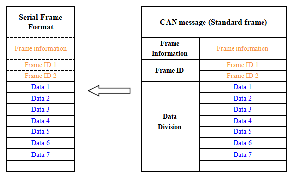
- If during configuration, the "Convert CAN Message to Serial" option is enabled, the converter will directly fill the "Frame Information" byte(s) of the CAN message into the serial frame. *Similarly, if the "Convert CAN Frame ID to Serial" option is enabled, it will fill all the "Frame ID" byte(s) of the CAN message into the serial frame.
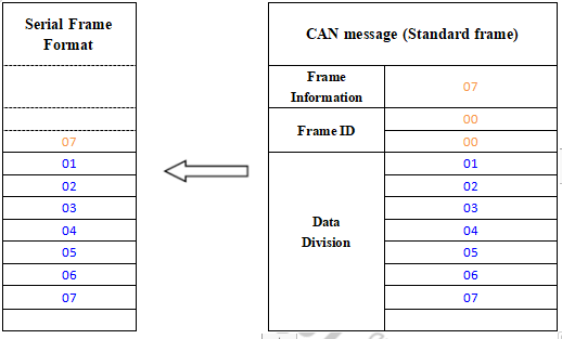
- For instance, if "Convert CAN Message to Serial" is enabled but "Convert CAN Frame ID to Serial" is not, the CAN frame converted to serial appears as illustrated below:
Transparent Conversion With ID
- Transparent conversion with ID is a specialized use of transparent conversion that facilitates users in constructing their networks more conveniently and employing custom application protocols.
- This method automatically converts the address information from a serial frame into the frame ID of the CAN bus. By informing the converter about the starting address and length of this address in the serial frame during configuration, the converter extracts this frame ID and converts it into the frame ID field of the CAN message. This serves as the ID of the CAN message when forwarding this serial frame. When converting a CAN message into a serial frame, the ID of the CAN message is also translated into the respective position within the serial frame. It's important to note that, in this conversion mode, the "CAN ID" setting in the "CAN Parameter Settings" of the configuration software is invalid. This is because, in this scenario, the transmitted identifier (frame ID) is populated from the data within the aforementioned serial frame.
UART to CAN
- Upon receiving a complete serial data frame, the converter promptly forwards it to the CAN bus.
- The CAN ID carried within the serial frame can be set within the configuration, specifying its starting address and length within the serial frame. The range for the starting address is from 0 to 7, while the length ranges from 1 to 2 for standard frames and 1 to 4 for extended frames.
- During conversion, based on the pre-configured settings, all CAN frame IDs within the serial frame are entirely translated into the frame ID field of the CAN message. If the number of frame IDs within the serial frame is fewer than the number of frame IDs within the CAN message, the remaining IDs within the CAN message are filled in the order of ID1 to ID4, with the remaining one filled with "0". The rest of the data undergoes sequential conversion as shown in the diagram.
- If a single CAN message frame does not complete the conversion of the serial frame data, the same ID continues to be used as the frame ID for the CAN message until the entire serial frame has been completely converted.
For example, the initial address of the CAN ID in the serial frame is 0, the length is 3 (in the extended frame), and the serial frame and the CAN message are as shown below. Note that the two frames of CAN messages are converted in the same ID.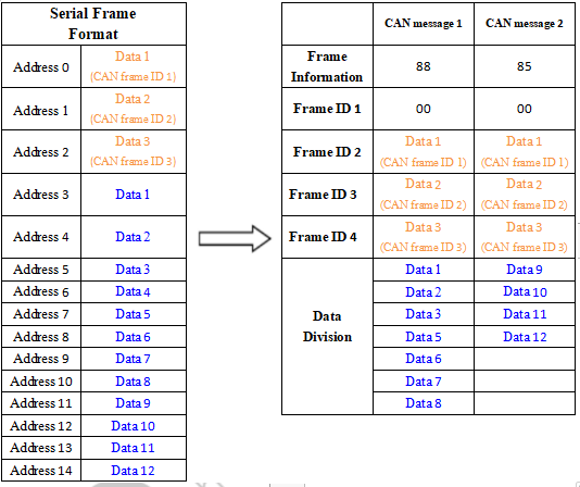
CAN Frame to UART
If the initial address of the configured CAN ID is 0 in the serial frame and a length of 3 (in the case of extended frames), the CAN message and the result of converting it to a serial frame are shown below: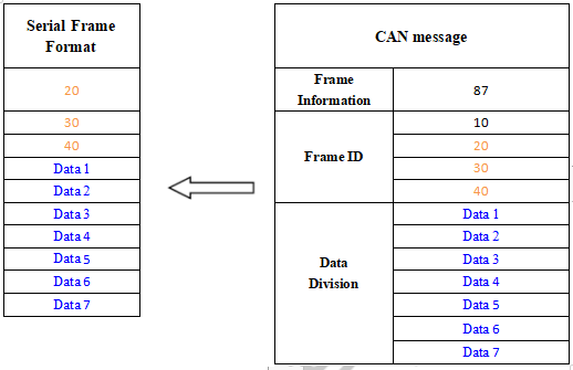
Format Conversion
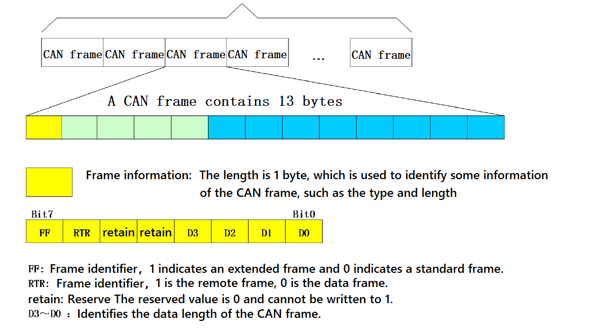
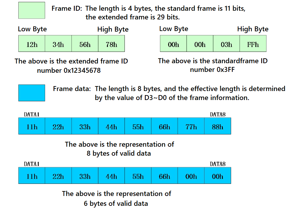
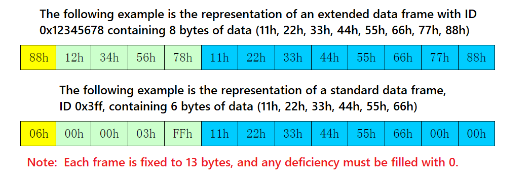
- This is the simplest mode of use and the data format is agreed to be 13 bytes, which contains all the information of the CAN frame.
Conversion Explanation
- Data conversion format as shown below. Each CAN frame includes 13 bytes, and they include CAN information + ID + data.
Modbus Protocol Conversion
*Convert the standard Modbus RTU serial data protocol to the specified CAN data format, and this conversion generally requires the editable CAN bus device message.
- The serial data must be compliant with the standard Modbus RTU protocol, otherwise it can not be converted. Please note that CRC parity can not be converted to CAN.
- The CAN formulates a simple and efficient segment communication format to realize Modbus RTU communication, which does not differentiate between host and slave, and users only need to communicate according to the standard Modbus RTU protocol.
- The CAN does not require CRC checksum, and after the converter receives the last CAN frame, the CRC will be added automatically. Then, a standard Modbus RTU data packet is formed and sent to the serial port.
- In this mode, the [CAN ID] of the [CAN Parameter Setting] of the configuration software is invalid, because the identifier (frame ID) sent at this time is filled by the address field (node ID) in the Modbus RTU serial frame.
Serial Frame Format (Modbus RTU)
- Serial parameter: baud rate, data bits, stop bits, and parity bits can be set via configuration software.
- The data protocol needs to conform to the standard Modbus RTU protocol.
CAN Frame Format
- The CAN side designs a set of segment protocol formats, which defines designed a segmentation protocol format that defines a method for segmenting and reorganizing a message that is greater than 8 bytes in length, as shown below.
- Note that when the CAN frame is a single frame, the segmentation flag bit is 0x00.
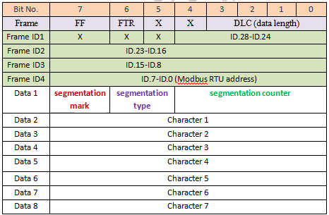
- The CAN frame message can be set by the configuration software (remote or data frame; standard or extended frame).
- The transmitted Modbus protocol starts from “Data 2” byte, if the protocol content is more than 7 bits, and the rest of the protocol content is converted in this segmented format until the conversion is complete.
- Data 1 is a segmentation control message (1 byte, 8bit), and the meaning is shown below:
Segmentation Mark
The segmentation mark occupies one bit (Bit7) and indicates whether the message is segmented or not. "0" indicates a separate message, and "1" indicates a frame in a segmented message.
Segmentation Type
The segmentation type occupies 2 Bits (Bit6, Bit5), and indicates the types of the report in this segment report.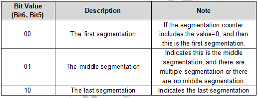
Segmentation Counter
Occupies 5 bits (Bit4-Bit0), used to distinguish the serial number of segments in the same frame Modbus message, enough to verify whether the segments of the same frame are complete.
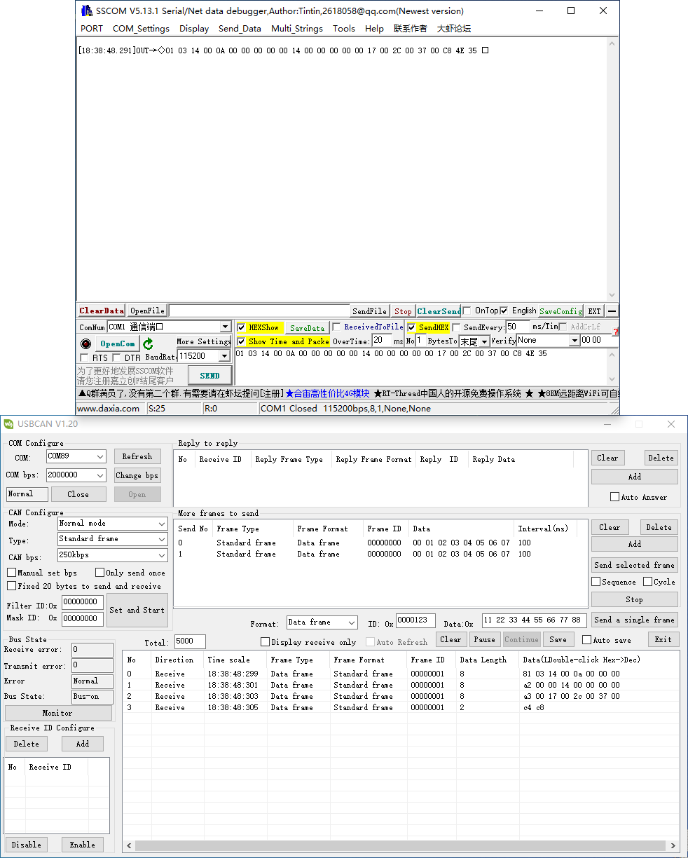
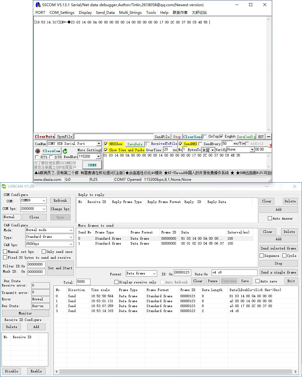
Conversion Example
- The serial port side Modbus RTU protocol (in hex).
- 01 03 14 00 0A 00 00 00 00 00 14 00 00 00 00 00 17 00 2C 00 37 00 C8 4E 35
- The first byte 01 is the Modbus RTU address code, converted to CAN ID.7-ID.0;
- The last 2 bytes (4E 35) are Modbus RTU CRC checksums, which are discarded and not converted.
- The final conversion to the CAN data message is as follows:
- Frame 1 CAN message: 81 03 14 00 0A 00 00 00 00
- Frame 2 CAN message: a2 00 00 14 00 00 00 00 00
- Frame 3 CAN message: a3 00 17 00 2C 00 37 00
- Frame 4 CAN message: c4 c8
- The frame type (standard or extended frame) of the CAN telegrams is set via the configuration software;
- The first data of each CAN message is filled with segmented information (81, a2, a3, and c4), which is not converted into Modbus RTU frames, but only serves as acknowledgment control information for the message.
- The conversion principle of data from the CAN side to ModBus RTU is the same as the above, after the CAN side receives the above four messages, the converter will combine the received CAN messages into a frame of RTU data according to the CAN segmentation mechanism mentioned above, and add CRC checksum at the end.
Verify the Function
RS232 TO CAN Test
Use USB-CAN-A and USB TO 4CH Serial Converter to demonstrate.
Hardware Connection
- Connect to the CAN device:
RS232/485/422 TO CAN - CAN USB-CAN-A CAN - CAN H CAN - CAN H CAN - CAN L CAN - CAN L CAN - CAN G CAN - GND
- Connect to RS232 device
RS232/485/422 TO CAN - RS232 USB TO 4CH Serial Converter - Port D RS232 - GND Port D - GND RS232 - TXD Port D - RXD RS232 - RXD Port D - TXD
Software Operation
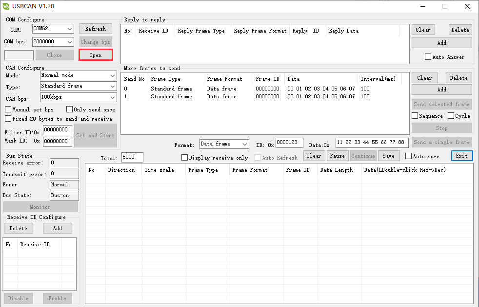
- Open USB-CAN-A-TOOL.
- Select the corresponding COM port of the USB-CAN-A, and click on "Open".

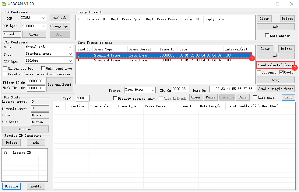
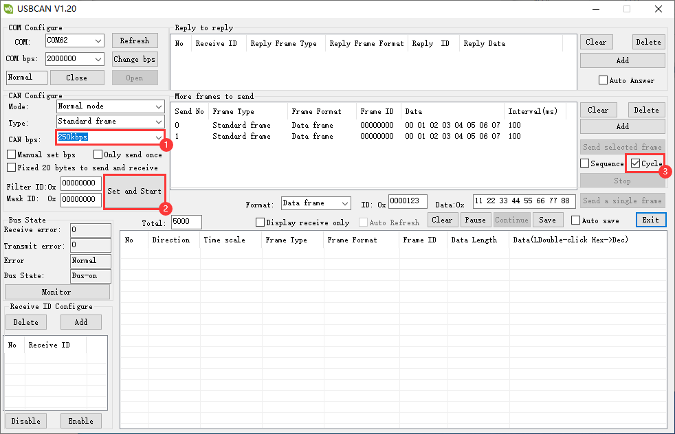
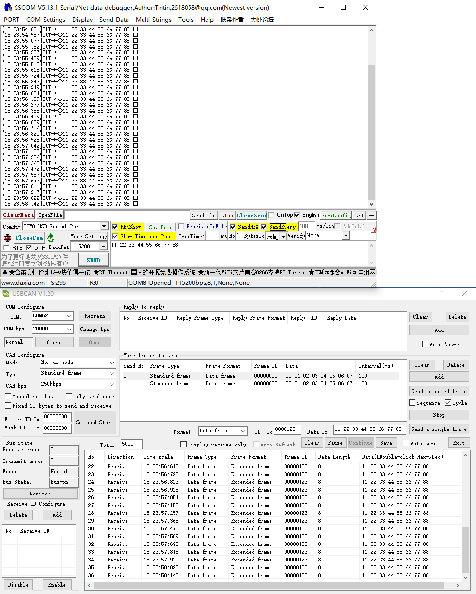
- Select the baud rate of the CAN device as 250kbps, click on "Send and start" , input the data to send, and select "Cycle".

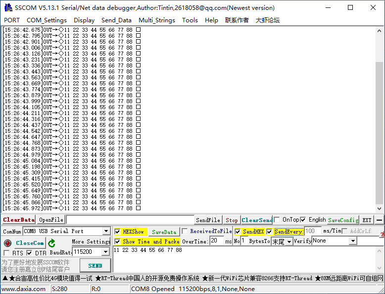
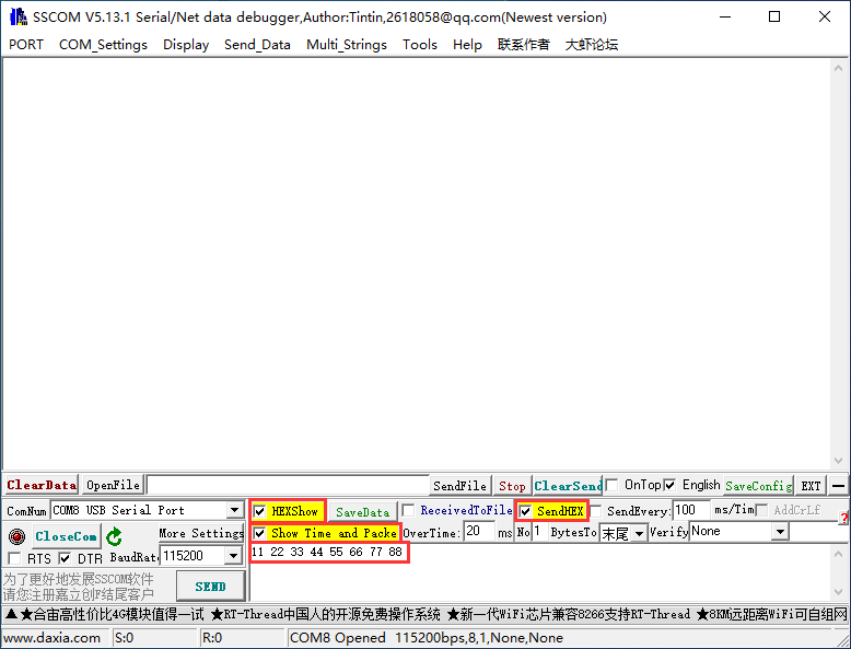
- Open an SSCOM, select the corresponding COM port of the USB TO 4CH Serial Converter's Port D, and open the serial port.
- In the SSCOM software, check Hexshow and show time and package, input the data to be sent.
11 22 33 44 55 66 77 88

- Select data in USB-CAN-A_TOOL, click on "Send selected frame".

- And then you can see that it transmits and receives.

- Or you can click on "Send every...ms/Time".

- And then you can see that it transmits and receives.

RS485 TO CAN Test
Use USB-CAN-A and USB TO 4CH Serial Converter to demonstrate.
Hardware Connection
- Connect to the CAN device.
RS232/485/422 TO CAN - CAN USB-CAN-A CAN - CAN H CAN - CAN H CAN - CAN L CAN - CAN L CAN - CAN G CAN - GND
- Connect to the RS485 device.
RS232/485/422 TO CAN - RS485 USB TO 4CH Serial Converter - Port C RS485 - GND Port C - GND RS485 - A+ Port C - A+ RS485 - B- Port C - B-
Software Operation
- Open USB-CAN-A-TOOL.
- Select the corresponding COM port of the USB-CAN-A, and click on "Open".

- Select the baud rate of the CAN device as 250kbps, click on "Send and start" , input the data to send, and select "Cycle".

- Open an SSCOM, select the corresponding COM port of the USB TO 4CH Serial Converter's Port C, and open the serial port.
- In the SSCOM software, check Hexshow and show time and package, input the data to be sent.
11 22 33 44 55 66 77 88

- Select data in USB-CAN-A_TOOL, click on "Send selected frame".
- And then you can see that it transmits and receives.

- Or you can click on "Send every...ms/Time".
- And then you can see that it transmits and receives.
RS422 TO CAN Test
Use USB-CAN-A and USB TO 4CH Serial Converter to test the functions.
Hardware Connection
- Connect to CAN device:
RS232/485/422 TO CAN - CAN USB-CAN-A CAN - CAN H CAN - CAN H CAN - CAN L CAN - CAN L CAN - CAN G CAN - GND
- Connect to RS422 device
RS232/485/422 TO CAN - RS422 USB TO 4CH Serial Converter - Port C RS422 - GND Port C - GND RS422 - TA Port C - RA RS422 - TB Port C - RB RS422 - RA Port C - TA RS422 - RB Port C - TB
Software Operation
- Open USB-CAN-A-TOOL.
- Select the corresponding COM port of the USB-CAN-A, and click on "Open".
- Select the baud rate of the CAN device as 250kbps, click on "Send and start" , input the data to send, and select "Cycle".
- Open an SSCOM, select the corresponding COM port of the USB TO 4CH Serial Converter's Port C, and open the serial port.


- In the SSCOM software, check Hexshow and show time and package, input the data to be sent.
11 22 33 44 55 66 77 88
- Select data in USB-CAN-A_TOOL, click on "Send selected frame".

- And then you can see that it transmits and receives.

- Or you can click on "Send every...ms/Time".

- And then you can see that it transmits and receives.
RS485 CAN HAT Expansion
RS485 CAN HAT Related User's Guide.
Please understand the usage of RS485 CAN HAT first.
Interface Expansion
CAN Interface Expansion
- Connect to RS485 interface, and the RS485 CAN HAT expands as 2x CAN interfaces.
RS232/485/422 TO CAN - RS485 RS485 CAN HAT RS485 - A+ RS485 - A+ RS485 - B- RS485 - B-
RS232/485/422 Interface Expansion
- Connect to the CAN interface, and then the RS485 CAN HAT expands as 1x RS485 interface and 1x RS232/RS485/422 interface.
RS232/485/422 TO CAN - CAN RS485 CAN HAT CAN - CAN H CAN - CAN H CAN - CAN L CAN - CAN L
Example
Use RS232/485/422 TO CAN for the communication between RS485 and CAN.
Hardware Connection
RS232/485/422 TO CAN - RS485 RS485 CAN HAT CAN - CAN H CAN - CAN H CAN - CAN L CAN - CAN L RS485 - A+ RS485 - A+ RS485 - B- RS485 - B-
Software Operation
Preparation
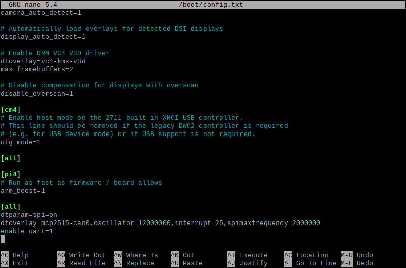
- Connect the RS485 CAN HAT to the Raspberry Pi, and modify the boot script "config.txt".
sudo nano /boot/config.txt
- Add the following content at the last line:
dtparam=spi=on
dtoverlay=mcp2515-can0,oscillator=12000000,interrupt=25,spimaxfrequency=2000000
- Also find the following configuration statement in /boot/config.txt to enable the serial port, or add it to the end of the file if it is not there.
enable_uart=1
Install Library
The following operation is required.
Install can-units
sudo apt-get install can-utils
Install wiringpi environment
#Open the Raspberry Pi terminal and run the following commands
cd
sudo apt-get install wiringpi
#For Raspberry Pi systems after May 2019 (earlier may not be performed), an upgrade may be required:
wget https://project-downloads.drogon.net/wiringpi-latest.deb
sudo dpkg -i wiringpi-latest.deb
gpio -v
# Running gpio -v will bring up version 2.52, if it doesn't it means there was an installation error
Install Python Environment
sudo apt-get update
sudo apt-get install python3-pip
sudo apt-get install python-serial
- Configure the running environment
sudo pip install python-can
- If running the above commands fails, you can download the following image:
sudo pip install -i https://pypi.tuna.tsinghua.edu.cn/simple python-can
sudo pip install -i https://mirrors.aliyun.com/pypi/simple python-can
sudo pip install -i https://pypi.mirrors.ustc.edu.cn/simple python-can
Modify RS232/485/422 TO CAN Configuration
- Use the software to modify the CAN id of the RS232/485/422 TO CAN.
- Set the CAN ID as "123", and operate it by following the #Device Configuration
C Example
- If you have already downloaded, please skip the file deletion step and the program download step (the two steps below).
- Delete the previously downloaded package. Please note: If you want to keep the original RS485_CAN_HAT_Code file, please copy it to another path.
cd
rm -rf RS485_CAN_HAT_Code.zip
rm -rf RS232-485-422_Code.zip
rm -rf RS485_CAN_HAT_Code
sudo ifconfig can0 down
- Download the example demo:
cd
sudo apt-get install unzip
wget https://files.waveshare.com/wiki/RS232-485-422-TO-CAN/RS232-485-422_Code.zip
unzip RS232-485-422_Code.zip
sudo chmod 777 -R RS485_CAN_HAT_Code/
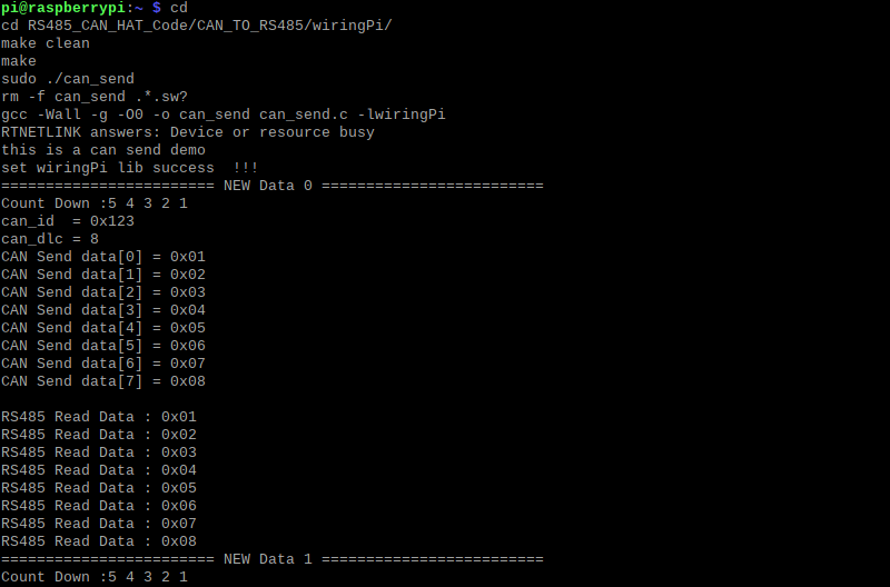
- CAN sends and the RS485 receives:
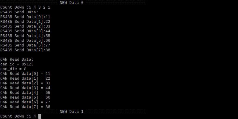
cd
cd RS485_CAN_HAT_Code/CAN_TO_RS485/wiringPi/
make clean
make
sudo ./can_send
- RS485 sends and CAN receives:
cd
cd RS485_CAN_HAT_Code/RS485_TO_CAN/wiringPi/
make clean
make
sudo ./485_send
Python Example
- If you have already downloaded, please skip the file deletion step and the program download step (the two steps below).
- Delete the previously downloaded package. Please note: If you want to keep the original RS485_CAN_HAT_Code file, please copy it to another path.
cd
rm -rf RS485_CAN_HAT_Code.zip
rm -rf RS232-485-422_Code.zip
rm -rf RS485_CAN_HAT_Code
sudo ifconfig can0 down
- Download the demo:
cd
sudo apt-get install unzip
wget https://files.waveshare.com/wiki/RS232-485-422-TO-CAN/RS232-485-422_Code.zip
unzip RS232-485-422_Code.zip
sudo chmod 777 -R RS485_CAN_HAT_Code/
- Reopen the can0, CAN sends and RS485 receives:
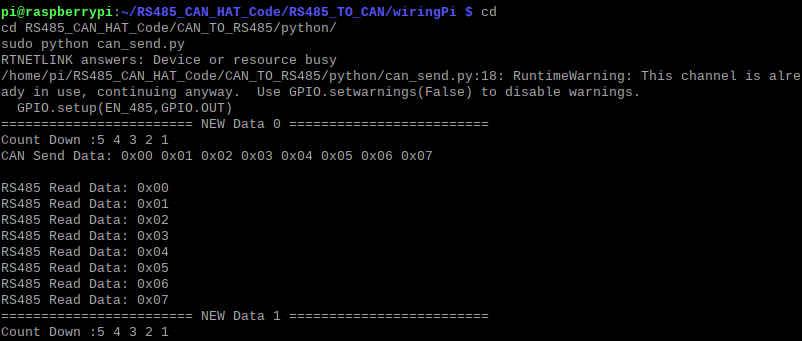
cd
cd RS485_CAN_HAT_Code/CAN_TO_RS485/python/
sudo python can_send.py
- Reopen the can0, RS485 sends and CAN receives:
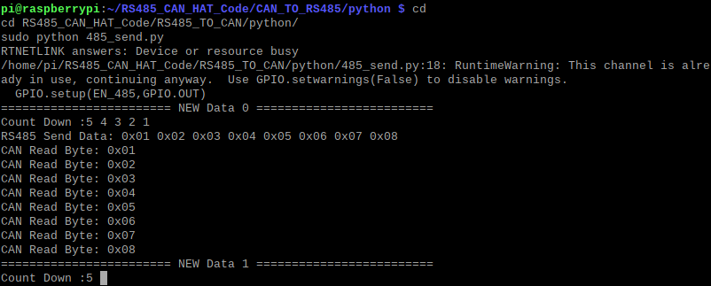
cd
cd RS485_CAN_HAT_Code/RS485_TO_CAN/python/
sudo python 485_send.py