


- sales/support
Google Chat:---
- sales
+86-0755-88291180
- sales01
sales@spotpear.com
- sales02
dragon_manager@163.com
- support
tech-support@spotpear.com
- CEO-Complaints
zhoujie@spotpear.com
- Only Tech-Support
WhatsApp:13246739196
- Purchase/Shipping/Refund
WhatsApp:13424403025
- HOME
- >
- ARTICLES
- >
- Common Moudle
- >
- ESP
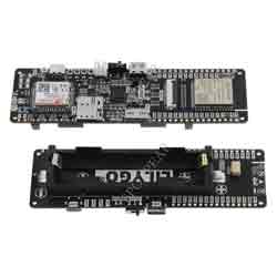
T-SIM7080G-S3 User Guide
【Examples preview】
examples
├─AllFunction # Full function test example
├─BLE5_extended_scan # Official BLE5 Example
├─BLE5_multi_advertising # Official BLE5 Example
├─BLE5_periodic_advertising # Official BLE5 Example
├─BLE5_periodic_sync # Official BLE5 Example
├─BIGIOT_Gnss_Upload # Upload positioning coordinates to BIGIOT IOT,Timed wake-up consumes about 1.2mA
├─MinimalCameraExample # Example of camera use
├─MinimalModemGPSExample # SIM7080G GPS example
├─MinimalModemNBIOTExample # SIM7080G NBIOT example
├─MinimalModemPowerSaveMode # SIM7080G power maintenance example
├─MinimalModemSleepMode # SIM7080G sleep example
├─MinimalModemUpgrade # Upgrade SIM7080 built-in firmware
├─MinimalPowersExample # Example of PMU
├─MinimalSDCardExample # Example of using SDCard
├─ModemMqttPulishExample # MQTT Pulish Example
├─ModemMqttsExample # MQTTS Example
└─ModemMqttSubscribeExample # MQTT Subscribe Example
【Quick Start】
PlatformIO
- Install VisualStudioCode and Python
- Search for the
PlatformIO plugin in the VisualStudioCode extension and install it. - After the installation is complete, you need to restart
VisualStudioCode - After restarting
VisualStudioCode, select File in the upper left corner of VisualStudioCode -> Open Folder -> select the LilyGo-T-SIM7080G directory - Click on the
platformio.ini file, and in the platformio column, cancel the sample line that needs to be used, please make sure that only one line is valid - Click the (√) symbol in the lower left corner to compile
- Connect the board to the computer USB
- Click (→) to upload firmware
- Click (plug symbol) to monitor serial output
PlatformIO plugin in the VisualStudioCode extension and install it.VisualStudioCodeVisualStudioCode, select File in the upper left corner of VisualStudioCode -> Open Folder -> select the LilyGo-T-SIM7080G directoryplatformio.ini file, and in the platformio column, cancel the sample line that needs to be used, please make sure that only one line is validArduinoIDE
- Install ArduinoIDE
- Copy all the folders in the
LilyGo-T-SIM7080G/lib directory to <C:\Users\UserName\Documents\Arduino\libraries>. If there is no libraries directory, please create a new one. Please note that you are not copying the lib directory, but copying the folders in the lib directory - Open ArduinoIDE -> Tools
- Board -> ESP32S3 Dev Module
- USB CDC On Boot -> Enable ## Note that you need to change Enable to Disable when USB is not connected, so USB CDC will not prevent the board from starting
- CPU Frequency -> 240MHz
- USB DFU On Boot -> Disable
- Flash Mode -> QIO 80MHz
- Flash Size -> 16MB(128Mb)
- USB Firmware MSC On Boot -> Disable
- PSRAM -> OPI PSRAM
- Partition Scheme -> 16M Flash(3MB APP/9.9MB FATFS)
- USB Mode -> Hardware CDC and JIAG
- Upload Mode -> UART0/Hardware CDC
- Upload Speed -> 921600
- Insert USB into the PC and click Upload <If the upload fails, keep pressing the BOOT button, click RST, and then click Upload. When the upload is complete, click RST to exit the download mode>
【Tips】
LilyGo-T-SIM7080G/lib directory to <C:\Users\UserName\Documents\Arduino\libraries>. If there is no libraries directory, please create a new one. Please note that you are not copying the lib directory, but copying the folders in the lib directory- Note: SIM7080G cannot connect to cellular network and GPS positioning at the same time
- Board integrated PMU (Power management chip), with short circuit and overload protection. By default,
PWRKEYneeds to be pressed for 6 seconds to turn off the board power supply, and pressPWRKEYfor 128 milliseconds to turn on the power supply. If you need to modify the power off pressing time, please refer toMinimalPowersExample - If the charging function is required, the
PMU TS Pindetection function needs to be turned off. By default, there is no NTC sensor on the board, so the TS Pin detection needs to be disabled before the charging function can be used normally. If theTS Pindetection function is not turned off, the PMU charging indicator will flash after the battery is inserted, and charging will be disabled - The board
VSYS is the internal 5V boost output of the PMU, which can only be output but not input. Please do not connect an external power supply load greater than 500mA - The
DC5 power supply voltage can be adjusted, and the maximum output current should not exceed 1A 5.DC1 is the core power supply voltage, and the default output is 3.3V. Please do not adjust the DC1 voltage through software - When the sketch cannot be uploaded, please press and hold the
BOOT button on the board, and then insert the USB. At this time, you should be able to see the port in the device manager of the computer, and then click Upload Sketch again - When the power supply channel of the
ESP32S3 is closed incorrectly, please insert USB, and then press and hold the BOOT button of the board, and then press and hold the PWRKEY button. At this time, the board enters the download mode, and the sketch can be uploaded normally - If the power supply of the board cannot be turned on when the battery is connected, please check that the mechanical switch beside the USB is turned to
ON, and then press the board PWR for 2 seconds. At this time, the board should start to work - The range of solar input voltage is
4.4~6V. Please select an appropriate solar panel and set the maximum charging current as 500mA - If the camera is not connected, all IO ports are available. If the camera is used, the board has only
GPIO45 and GPIO46 is idle T-SIM7080G uses Octal SPI PSRAM, so GPIO35~GPIO37 is unavailable. Please do not use these IOs- Note: Please understand the risks to be faced before changing the voltage of peripherals, otherwise do not try to change the voltage of cameras and other on-board devices, which may cause permanent damage
- Note: Please do not turn off the BLDO1 power supply, otherwise ESP32S3 and SIM7080G cannot communicate normally
- Please check the Operating Instructions for updating the built-in firmware of the modem. Generally, upgrading the firmware is not recommended
【Pins】
PWRKEYneeds to be pressed for 6 seconds to turn off the board power supply, and pressPWRKEYfor 128 milliseconds to turn on the power supply. If you need to modify the power off pressing time, please refer toMinimalPowersExamplePMU TS Pindetection function needs to be turned off. By default, there is no NTC sensor on the board, so the TS Pin detection needs to be disabled before the charging function can be used normally. If theTS Pindetection function is not turned off, the PMU charging indicator will flash after the battery is inserted, and charging will be disabledVSYS is the internal 5V boost output of the PMU, which can only be output but not input. Please do not connect an external power supply load greater than 500mADC5 power supply voltage can be adjusted, and the maximum output current should not exceed 1A 5.DC1 is the core power supply voltage, and the default output is 3.3V. Please do not adjust the DC1 voltage through softwareBOOT button on the board, and then insert the USB. At this time, you should be able to see the port in the device manager of the computer, and then click Upload Sketch againESP32S3 is closed incorrectly, please insert USB, and then press and hold the BOOT button of the board, and then press and hold the PWRKEY button. At this time, the board enters the download mode, and the sketch can be uploaded normallyON, and then press the board PWR for 2 seconds. At this time, the board should start to work4.4~6V. Please select an appropriate solar panel and set the maximum charging current as 500mAGPIO45 and GPIO46 is idleT-SIM7080G uses Octal SPI PSRAM, so GPIO35~GPIO37 is unavailable. Please do not use these IOs| Camera | PWDN | Reset | XCLK | SDA | SCL | VSYNC | HREF | PCLK |
|---|---|---|---|---|---|---|---|---|
| GPIO | N/A | 18 | 8 | 2 | 1 | 16 | 17 | 12 |
| Camera | D9 | D8 | D7 | D6 | D5 | D4 | D3 | D2 |
| GPIO | 9 | 10 | 11 | 13 | 21 | 48 | 47 | 14 |
- If you do not use a camera, you can freely allocate IO ports here. Assuming you need to allocate I2C, please use the display to call Wire and pass the required IO ports, such as
int sda = 13; // You can also use other IO ports
int scl = 21; // You can also use other IO ports
Wire.begin(sda,scl)
| Modem | PWR | RXD | TXD | RI | DTR |
|---|---|---|---|---|---|
| GPIO | 41 | 4 | 5 | 3 | 42 |
| PMU | SDA | SCL | IRQ |
|---|---|---|---|
| GPIO | 15 | 7 | 6 |
| SDCard | CMD | CLK | DATA |
|---|---|---|---|
| GPIO | 39 | 38 | 40 |
| Modem | Camera | ESP32S3 | SDCard | Level conversion |
|---|---|---|---|---|
| DC3/BLDO2(GPS) | ALDO1/ALDO2/ALDO4 | DC1 | ALDO3 | BLDO1 |
TAG:
RS485 to CAN
Raspberry Pi Pico
Raspberry Pi Pico 2 RP2350 With 0.96 inch LCD Display 0.96inch Screen 160×80 Onboard RP2350A
Raspberry Pi 5 PCIe to USB Gen1 HUB and M.2 NVMe SSD PI5 Expansion board HAT+
Raspberry Pi 7.5 inch e-Paper link (H) RYBW 800x480 For Arduino / Jetson Nano / STM32
ESP32 MLX90640
ESP32-AI Series User Guide
Industrial RS485 Modbus RTU Relay
Raspberry Pi 5 PCIe to USB3.2 Gen1 Hub 5Gbps For Raspberry Pi OS Drive free
Raspberry Pi Pico 2 Plus RP2350 Board RP2350A
Raspberry Pi 8 inch DSI LCD Display With 5MP Front Camera MIPI 800×480 Capacitive TouchScreen
User Guide
Raspberry Pi
Milk-V Duo RJ45
Wiki
Raspberry Pi CM5 to Pi 5 Expansion Board With USB microphone & Audio Port
ESP32-P4 Smart 86 TV Box Development Board 4 inch 720x720 Display TouchScreen RS485 Relay Camera RJ45 ETH
Core1121 LoRa LR1121 HF LF SPI For Sub-GHz and 2.4GHz
Raspberry Pi Pico 2 W RP2350 Pico2W ARM Cortex-M33 And RISC-V Hazard3 Wi-Fi4 Bluetooth5.2 CYW43439
Gyroscope Sensor
TAG:
Raspberry Pi 8 inch DSI LCD Display MIPI 800×480 Capacitive TouchScreen 5MP Front Camera
Raspberry Pi 5 inch e-Paper ink screen display black white 960×552 For Arduino /Jetson /STM32 /ESP32
ESP32 S3 AI 0.85inch Development Board 0.85 inch DeepSeek RGB surround light
Raspberry Pi 5 PCIe to SSD
Pi4
USB Watertight Camera 2MP PS5268 120dB HDR USB 2.0 Plug and Play
MINI linux board
PI4B
XIAO-nRF52840 Plus
Raspberry Pi 5 Speaker
RDK X5 PoE
UART
Jetson Nano
Raspberry Pi Pico 2 RP2350 LCD 0.96 inch Displayscreen RP2350A
Raspberry Pi RP2040 HM01B0
MAX9296 GMSL Camera 2-Ch High-Speed Low-Latency Transmission Jetson Orin Nano/NX
Sipeed MaixCAM RISC-V YOLO AI Camera WIFI6 SG2002 Linux
Raspberry Pi 4inch DSI Round LCD Display MIPI IPS 720xX720 Capacitive Touchscreen
Jetson Orin NX 8GB AI 70Tops Embedded Edge Systems NVIDIA
UART To Ethernet