- sales/support
Google Chat:---
- sales
+86-0755-88291180
- sales01
sales@spotpear.com
- sales02
dragon_manager@163.com
- support
tech-support@spotpear.com
- CEO-Complaints
zhoujie@spotpear.com
- Only Tech-Support
WhatsApp:13246739196
- Purchase/Shipping/Refund
WhatsApp:13424403025
UGV02 User Guide
Resource
Open-Source Demo
Drawing
Robot Model
Introduction
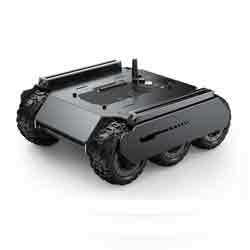
UGV02 is a 4WD six-wheel mobile robot chassis with superb off-road performance, shock absorbers, and open-source code that supports customization development. It supports external host computers (Raspberry Pi, Jetson Nano, Horizon Sunrise X3 Pi, etc.), and the host computer communicates with the ESP32 slave computer through the serial port.
The built-in UPS power supply module with 3S 18650 lithium battery (3x 18650 lithium batteries connected in series) provides uninterruptible power for the robot and supports charging and discharging at the same time. Also, with a built-in multi-functional robot driver board, it supports external serial bus servos, PWM servos, SD cards, and so on. The driver board is based on ESP32 with onboard WiFi and Bluetooth.
With flexible rubber tires, it can enjoy smooth driving on tough terrains. Also, it comes with 2x 10²⁰ European standard profile rails, which can easily meet the needs of heavy loads, shock absorption, and off-road performance, and provides more feasibility for customization development.
Features
- Comes with 203mm pitch 1020 aluminum extension rails (including boat nuts and screws) for flexible expansion of multiple peripherals.
- The use of flexible rubber tires substantially reduces the impact of complex terrain on the product.
- With 4WD six-wheel drive, it has excellent climbing ability.
- Equipped with interactive device 0.96-inch OLED screen.
- With a charging port and an automatic download circuit, you can use it while charging.
- The UPS power module with an onboard INA219 acquisition chip can facilitate real-time monitoring of battery voltage and charging current.
- The UPS power supply module has 3x 18650 batteries in series with 7800mAh. Higher output current, stronger motor power.
- The UPS power supply module also provides outputs of 5V and 3.3V for external other devices.
- The onboard lithium battery protection circuit of the UPS power supply module has anti-overcharge, anti-over-discharge, anti-overcurrent, and short circuit protection functions.
- The demo is developed on Arduino IDE, no need to manually configure the compilation environment, ESP32 automatically set a WIFI hotspot when it is turned on. You can use a mobile phone (Android/iOS) or a computer (Linux/Windows/Mac) to connect and log in to the control page by installing the Chromium browser, and no need to download an app.
- ESP32 can be used to drive DC motors, serial bus servos, onboard OLED screen interfaces, TF card slots, nine-axis IMU modules, WiFi, and Bluetooth, and can be used alone without installing the host computer.
- Can be extended with a variety of host computers, use the serial port to transmit data in JSON format to control.
- All code is open source and provides a wealth of development documentation and tutorials.
- Open-source extension flat drawings and chassis structural drawings, including 3D models, for easy secondary development.
UGV02 User Guide
Note: Please purchase and install three 18650 lithium batteries to be able to use them properly, it is recommended to use the high discharge rate of the battery.
UGV02 Basic Use
The driver board of UGV02 is developed based on the ESP32 module. After starting up, ESP32 will give priority to connecting to known WIFI hotspots (the following tutorial will introduce how to set up known WIFI). If the WIFI is not connected within 20 seconds after starting up, ESP32 will create a hotspot automatically.
Hotspot name: UGV02_BASE
Hotspot password: 12345678
After connecting to this hotspot with your mobile phone, the mobile phone will prompt you that this hotspot has no network, and whether you are allowed to switch hotspots, please choose not to, keep the connection with the UGV02_BASE hotspot.
Open the mobile browser (Google Chrome is recommended), visit the URL 192.168.4.1, and you can open the UGV02_BASE control page. You can send commands in JSON format on this page to control and set the onboard serial bus servo device, get the serial bus servo feedback, obtain IMU information, control the angle of the PWM servo, set the content of the OLED display, etc., which is convenient for users to develop on the host computer.
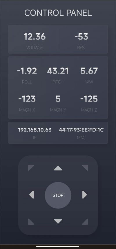
The web interface will display the robot's voltage, signal strength (STA mode), heading angle, IP and MAC address, and other information in real time.
The movement of the robot can be controlled by the direction buttons, and the SLOW, MIDDLE and FAST buttons below the direction buttons are used to select the moving speed of the robot.
The web page includes "heartbeat detection". After opening the web control interface, the web application will communicate with the robot continuously. If the connection is disconnected during the movement of the robot, the robot will automatically stop moving in a short time to avoid danger.
When using a tablet computer or PC to open the web control interface, you can use the WASD keys on the keyboard to control the robot. In order to avoid misuse, the first few shortcut keys after login are unresponsive, and you can start to control the robot by pressing the WASD keys once or several times in a cycle.
As the web application is completely open-source, you can change its interface and functions by changing WebPage.h. You can follow the customizable development tutorial we provide to learn.
UGV02's JSON Instruction Interaction Tutorial
What Is JSON?
JSON (JavaScript Object Notation) is an open standard file format and data interchange format that is easy for humans to read and write, and can exchange data between multiple languages. It is also easy for machines to parse and generate.
Why Interact With JSON Commands and UGV01?
As UGV02 boasts more onboard resources, rich demo functions, and is easy to connect external host computers, it is easily controlled by the host computer in more aspects. Hence, we can use JSON commands to interact with UGV02. Also, we can customize these functions based on the current framework to make them more suitable for your needs.
JSON Commands Interaction Method
We provide two interaction methods for UGV02 and the JSON commands:
1. Through the web application (or send a request through the program, which can be used for wireless JSON interaction with the host computer).
2. Through UART communication. The 40PIN expansion header on the driver board of UGV01 has a corresponding RX and TX header, using a 3.3V logic level (applicable to host computers such as Raspberry Pi, Jetson nano, etc., not suitable for Arduino Uno with a serial port logic level of 5V.) Also, you can interact with the host computer through the Type-C connector and USB interface. There are two Type-C connectors on the UGV02 driver board, and the Type-C connector in the middle is used to communicate with the ESP32 and upload the demo, no matter which way you use to connect to the host computer, the communication baud rate is 1000000.
JSON Commands Using Way
After opening the web control interface, you will see the "FEEDBACK INFORMATION" section at the bottom of the interface. Above this section, there is an input field and a "SEND" button. You can fill in the JSON data in this input field and click the "SEND" button. If the command has feedback, the feedback information will be displayed above the input field. Below the input field, you can find examples of JSON commands. Each example is followed by an "INPUT" button. Clicking on it will populate the input field with the corresponding command. You can edit the command in the input field and then interact with the robot by pressing the "SEND" button.
Alternatively, you can use a host computer to generate JSON commands and send them to the robot via the serial port. The baud rate is 1000000, and the logic level of the serial port's RX/TX pins is 3.3V. You can also use a USB cable with a Type-C interface for communication.
Next, I will explain each JSON command. Let's take the JSON command for controlling movement as an example. The JSON command for controlling movement is "SPEED_INPUT" followed by {"T":1,"L":0.5,"R":0.5}. Click the "INPUT" button next to this command, and it will be filled in the input field above. The first parameter in every JSON command is "T," which represents the command type. For example, "T":1 indicates that it is a command for controlling the robot's movement. In addition to the "T" parameter, there are "L" and "R" parameters, which control the power of the left and right motors respectively. The values can range from -1 to +1 (higher values indicate higher motor power and faster speed, positive values for forward motion, and negative values for backward motion). However, due to the low-speed characteristics of DC gear motors, the absolute value of the power value should be greater than or equal to 0.2. When the absolute value of the speed is less than 0.2 but not zero, the motors will run at 20% power. When the speed is positive, the wheels move forward; when the speed is 0, the wheels stop rotating; and when the speed is negative, the wheels move backward.
For example, if you want the robot to move backward at full speed, you can edit the command as {"T":1,"L":-1,"R":-1}. After clicking the "SEND" button, the robot will move backward at full speed for a certain period of time and then stop. Due to heartbeat detection, if the robot does not receive new commands within a certain period of time, it will automatically stop running to avoid danger.
The following content is for introducing the JSON commands.
EMERGENCY_STOP: {"T":0}Emergency stop command, if the command type T has no corresponding function, it will also trigger an emergency stop.
SPEED_INPUT: {"T":1,"L":0.5,"R":0.5}In the movement control command, the parameters represent the left motor power and right motor power respectively, the speed value can be positive or negative, for ±1 for a full load operation, and for 0 to stop, the absolute value of the action needs to be greater than 0.2 and less than 1.
PID_SET: {"T":2,"P":170,"I":90}PID control of motor closed-loop control, note that this function is not applicable to chassis without speed feedback like UGV02.
OLED_SET: {"T":3,"lineNum":0,"Text":"putYourTextHere"}The OLED screen display content setting, the lineNum parameter is the line setting, which can be: 0, 1, 2, 3, and a total of 4 lines of content can be displayed. Each time a line of content is set, the new content will not affect the content displayed in other lines but will replace the original content of this line.
The Text parameter is the content setting, you can enter text here, and the text will be displayed on the corresponding line.
After using this command, the OLED screen will no longer display the information about the robot but will display the content that the command asked it to display.
OLED_DEFAULT: {"T":-3}When the command type is -3, the OLED screen will be reset to the initial state, and the information about the robot will be displayed.
PWM_SERVO_CTRL: {"T":40,"pos":90,"spd":30}PWM servo angle control command, the PWM signal is generated by the IO4 pin of the driver board, the servo rotation range of most PWM signals is 0-180°, the pos parameter is the angle to be rotated, and 90° is the middle position of the servo, The spd parameter is a reserved speed interface. In order to avoid a stuck thread in the demo, the spd parameter is not used.
PWM_SERVO_MID: {"T":-4}The PWM servo turns to the middle position, which is the 90° position.
BUS_SERVO_CTRL: {"T":50,"id":1,"pos":2047,"spd":500,"acc":30}In the serial bus servo control command, here you need to pay attention to whether the operating voltage of the connected serial bus servo is consistent with the power supply voltage of the driver board, you can directly use our ST3215 serial bus servo.
id: The ID of the serial bus servo, cannot be the same as the serial bus servo connected to the driver board.
pos: The target position is to be rotated by the servo. For the ST3215 servo, this value can be 0-4095 in the angle control mode, corresponding to the clockwise rotation range of 0-360°. In the continuous rotation mode, values can be ±32766.
spd: the rotation speed of the serial bus servo, the number of steps per unit time (per second), 50 steps/second=0.732RPM (turn/minute), the larger the value, the faster the speed (but the speed of the servo has a limit), when the parameter is 0, it runs at the maximum speed.
acc: The acceleration of the bus servo rotation. The smaller the value, the smoother the start and stop. The value can be 0-254. If it is set to 10, the speed will be changed according to the square acceleration of 1000 steps per second. When the parameter is 0, it runs with the maximum acceleration.
BUS_SERVO_MID: {"T":-5,"id":1}Turn the bus servo of a certain ID to the middle position of the servo (provided that the operating mode of this servo is 0: position servo mode).
id: The ID of the target servo.
BUS_SERVO_SCAN: {"T":52,"num":20}This command is used to scan which servo IDs are connected to the bus, no duplicate IDs are allowed. The results are fed back and displayed above the input field.
num: The maximum ID of the servo, the larger the value, the longer the scan time.
BUS_SERVO_INFO: {"T":53,"id":1}To obtain the information feedback on a certain servo, the feedback content includes the position, speed, voltage, torque, and other information of the servo.
BUS_SERVO_ID_SET: {"T":54,"old":1,"new":2}It is used to change the ID of a servo. The ID of each new servo is 1 by default. If you don’t know the ID of the servo at hand, you can use the above BUS_SERVO_SCAN command to get it, but the premise is that when viewing the ID of the servo, the driver board is only connected to this servo, otherwise, you don't know which ID corresponds to which servo.
old: the ID of the servo whose ID is to be changed.
new: the new ID to set.
BUS_SERVO_TORQUE_LOCK: {"T":55,"id":1,"status":1}Servo torque lock switch.
id: The ID of the servo to control the torque lock.
status: Torque lock switch parameter, 1 is to turn on the torque lock, the servo will keep its position; 0 is to turn off the torque lock, and the servo will rotate under the action of external force.
BUS_SERVO_TORQUE_LIMIT: {"T":56,"id":1,"limit":500}Servo torque limit command.
id: The ID of the target servo.
limit: Torque limit ratio, 500 is 50%*locked-rotor torque, 1000 is 100%*locked-rotor torque, after the torque is limited when the servo receives external force when the torque of the external force is greater than the limited torque, the servo will follow the external force Rotation, but still provide this torque, this feature can be used to make the clamp of the robotic arm.
BUS_SERVO_MODE: {"T":57,"id":1,"mode":0}Servo operating mode.
id: Target servo ID.
mode: operation mode value. 0: position servo mode, used to control the absolute angle of the servo, you can use the BUS_SERVO_CTRL command to control the angle of the servo. 3: step servo mode, also use the BUS_SERVO_CTRL command to control it, the difference in the stepping servo mode is the pos parameter of BUS_SERVO_CTRL can be a negative number, and the range is ±32766, if you set 4096, it will rotate forward for one circle, if you set -4096, it will reverse for one circle.
WIFI_SCAN: {"T":60}WIFI scanning command, which will disconnect the existing WIFI connection and scan the surrounding WIFI hotspots.
WIFI_TRY_STA: {"T":61}WIFI connection command, STA mode, is used to connect to known WIFI.
WIFI_AP_DEFAULT: {"T":62}WIFI hotspot open command, AP mode, the robot will set a WIFI hotspot by itself.
Hotspot name: UGV02_BASE
Hotspot password: 12345678
WIFI_INFO: {"T":65}Used to obtain WIFI information.
WIFI_OFF: {"T":66}Close Wifi.
INA219_INFO: {"T":70}Obtain the information on INA219, including the voltage, current, and power of the power supply.
IMU_INFO: {"T":71}Used to obtain IMU information, including heading angle, geomagnetic field, acceleration, altitude, temperature, and other information.
ENCODER_INFO: {"T":73}Used to obtain motor encoder information.
DEVICE_INFO: {"T":74}It is used to obtain device information, which needs to be customized by the user, and is used to introduce the purpose of this device or other information.
IO_IR_CUT: {"T":80,"status":1}It is used to control the high and low levels of the IO5 pin on the driver board, which can be used to control the night vision function switch of the infrared camera and can also be used to control the relay.
SET_SPD_RATE: {"T":901,"L":1.0,"R":1.0}It is used to adjust the power of each side motor. When giving the same power to the left and right motors of the robot, if the robot is not moving in a straight line, you can use this command to fine-tune the power of the motors on both sides. This value will be used as a factor to multiply the output power of the motors to change the power of the motors.
L: power coefficient of the left wheel.
R: power coefficient of the right wheel.
GET_SPD_RATE: {"T":902}Get the velocity coefficients of the left and right wheels.
SPD_RATE_SAVE: {"T":903}Save the power coefficient of the motor, it will be saved in the nvs area of ESP32 and will not be lost after power down, and this speed coefficient will be read and loaded by the nvs area after power on.
GET_NVS_SPACE: {"T":904}Get the remaining space of nvs area of ESP32.
NVS_CLEAR: {"T":905}Clean up the nvs area, this command will delete all the contents of the nvs area, and the speed coefficient will return to the default value of 1.0.
Driver Board General Driver for Robots Module Usage Tutorial
- How To Install Arduino IDE
- Tutorial I: Motor With Encoder Control Demo
- Tutorial II: Motor Without Encoder Control Demo
- Tutorial III: ST3215 Serial Bus Servo Control Demo
- Tutorial IV: PWM Servo Control Demo
- Tutorial V: IMU Data Reading Demo
- Tutorial VI: SD Card Reading Demo
- Tutorial VII: INA219 Voltage And Current Monitoring Demo
- Tutorial VIII: OLED Screen Control Demo
Motor Parameters
- Model: JGB37-520 DC Geared Motors
- Rated voltage: 12V
- Rated current: 0.3A
- Locked-rotor current: 1.4A
- Rated torque: 2.4kg.cm
- Locked-rotor torque: 10.4kg.cm
- Rated output power: 1.3W
- No-load speed: 66±10%RPM
- Rated speed:51±10%RPM
- Motor size: 37*52mm
- Output shaft size: 6*15mm
- Single motor weight: 145g