- sales/support
Google Chat: zj734465502@gmail.com
- sales
+86-0755-88291180
- sales01
sales@spotpear.com
- sales02
dragon_manager@163.com
- support
tech-support@spotpear.com
- CEO-Complaints
zhoujie@spotpear.com
- sales/support
WhatsApp:13246739196
- HOME
- >
- ARTICLES
- >
- Hot Articles
- >
- Raspberry Pi
RPi Tutorial Series: I2C User Guide
This section explains how to enable I2C function for Raspberry Pi and operate I2C devices using I2C-tools.
Enable I2C
Configure your Pi and enable the I2C
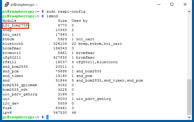
sudo raspi-config
Select Advanced Options -> I2C -> <YES> to enable the I2C driver by kernel. Then you can check if the I2C is enabled:
lsmod
If I2C enabled, the terminal echoes an i2c-bcm2708 device. Else you can also add it manually.
sudo nano /etc/modules
append:
i2c-bcm2708
i2c-dev
I2C-Tools
I2C-Tools are utilities for ease of monitoring and identifying I2C devices. These tools are also important for fault diagnosis. You can get the tools with:
sudo apt-get install i2c-tools
See: http://www.lm-sensors.org/wiki/i2cToolsDocumentation There are only 4 commands in I2C-tools. Here we introduce one by one.
1. i2cdetect is a userspace program to scan an I2C bus for devices.
i2cdetect -y 1
- -y Disable interactive mode. By default, i2cdetect will wait for a confirmation from the user before messing with the I2C bus. When this flag is used, it will perform the operation directly.
- 1 Indicates the number or name of the I2C bus to be scanned.
For example, if you plug the extension board Pioneer600 on your Pi, you will get:
     0  1  2  3  4  5  6  7  8  9  a  b  c  d  e  f
00:          -- -- -- -- -- -- -- -- -- -- -- -- --
10: -- -- -- -- -- -- -- -- -- -- -- -- -- -- -- --
20: 20 -- -- -- -- -- -- -- -- -- -- -- -- -- -- --
30: -- -- -- -- -- -- -- -- -- -- -- -- -- -- -- --
40: -- -- -- -- -- -- -- -- 48 -- -- -- -- -- -- --
50: -- -- -- -- -- -- -- -- -- -- -- -- -- -- -- --
60: -- -- -- -- -- -- -- -- 68 -- -- -- -- -- -- --
70: -- -- -- -- -- -- -- 77
- 0x20: address of PCF8574 IO extension chip.
- 0x48: address of PCF8591 AD/DA chip.
- 0x68: address of DS3231 RTC clock chip.
- 0x77: address of BMP180 pressure sensor.
2. i2cdump is a small helper program to examine registers visible through the I2C bus.
i2cdump -y 1 0x68
- -y Disable interactive mode. By default, i2cdump will wait for a confirmation from the user before messing with the I2C bus. When this flag is used, it will perform the operation directly.
- 1 Indicates the number or name of the I2C bus to be scanned.
- 0x68 Indicates the address to be scanned on that bus. Here is DS3231 RTC clock chip.
No size specified (using byte-data access)
     0  1  2  3  4  5  6  7  8  9  a  b  c  d  e  f    0123456789abcdef
00: 52 58 10 01 01 01 00 00 00 00 00 00 00 00 1c 88    RX????........??
10: 00 1f 00 XX XX XX XX XX XX XX XX XX XX XX XX XX    .?.XXXXXXXXXXXXX
20: XX XX XX XX XX XX XX XX XX XX XX XX 00 00 00 00    XXXXXXXXXXXX....
30: XX XX XX XX XX XX XX XX XX XX XX XX XX XX XX XX    XXXXXXXXXXXXXXXX
40: XX XX XX XX XX XX XX XX XX XX XX XX XX XX XX XX    XXXXXXXXXXXXXXXX
50: XX XX XX XX XX XX XX XX XX XX XX XX XX XX XX XX    XXXXXXXXXXXXXXXX
60: XX XX XX XX XX XX XX XX XX XX XX XX XX XX XX XX    XXXXXXXXXXXXXXXX
70: XX XX XX XX XX XX XX XX XX XX XX XX XX XX XX XX    XXXXXXXXXXXXXXXX
80: XX XX XX XX XX XX XX XX XX XX XX XX XX XX XX XX    XXXXXXXXXXXXXXXX
90: XX XX XX XX XX XX XX XX XX XX XX XX XX XX XX XX    XXXXXXXXXXXXXXXX
a0: XX XX XX XX XX XX XX XX XX XX XX XX XX XX XX XX    XXXXXXXXXXXXXXXX
b0: XX XX XX XX XX XX XX XX XX XX XX XX XX XX XX XX    XXXXXXXXXXXXXXXX
c0: XX XX XX XX XX XX XX XX XX XX XX XX XX XX XX XX    XXXXXXXXXXXXXXXX
d0: XX XX XX XX XX XX XX XX XX XX XX XX XX XX XX XX    XXXXXXXXXXXXXXXX
e0: XX XX XX XX XX XX XX XX XX XX XX XX XX XX XX XX    XXXXXXXXXXXXXXXX
f0: XX XX XX XX XX XX XX XX XX XX XX XX XX XX XX XX    XXXXXXXXXXXXXXXX
3. i2cset is a small helper program to set registers visible through the I2C bus.
i2cset -y 1 0x68 0x00 0x13
- -y Disable interactive mode. By default, i2cset will wait for a confirmation from the user before messing with the I2C bus. When this flag is used, it will perform the operation directly.
- 1 Indicates the number or name of the I2C bus to be scanned.
- 0x68 Specifies the address of the chip on that bus. Here is DS3231 RTC clock chip.
- 0x00 Specifies the address on that chip to write to.
- 0x13 If specified, is the value to write to that location on the chip.
4. i2cget is a small helper program to read registers visible through the I2C bus (or SMBus).
i2cget -y 1 0x68 0x00
- -y Disable interactive mode. By default, i2cget will wait for a confirmation from the user before messing with the I2C bus. When this flag is used, it will perform the operation directly.
- 1 Indicates the number or name of the I2C bus to be scanned.
- 0x68 Specifies the address of the chip on that bus. Here is DS3231 RTC clock chip.
- 0x00 specifies the address on that chip to read from.
Control PCF8574 IO using i2c-tools
Here is an example.
Write data to IO
PCF8574 is a I2C chip which can expand IO up to 8 and the initial state of IO is HIGH. Different from other I2C chips, the PCF8574 has no register, instead, a byte to specify the address on that chip to write to is always used to control the IO:
i2cset -y 1 0x20 0xEF
- 0x20: address of PCF8574 IO extension chip.
- 0xEF: this often specifies the address on that chip to write to, but PCF8574 has no register so this byte is used to control the IO. It sets the P4 pin LOW ouput and other pins of the chip HIGH output. The LOW output of P4 pin also turn on the LED2 on the Pioneer600, because the LED2 is turned on by LOW input and connected to the P4 pin of PCF8574.
As the same, you can use i2c-tools to control the buzzer on the Pioneer600. The buzz is connected to the P7 pin of PCF8574: Buzzer on:
i2cset -y 1 0x20 0x7F
Buzzer off:
i2cset -y 1 0x20 0xFF
Read data from IO
Used the command line to read the IO state of PCF8574
i2cget -y 1 0x20
- 0x20: address of PCF8574 IO extension chip.
Control PCF8574 IO Based on Libraries
Some examples are given in this part to explain how to write data via I2C bus using BCM2835, WiringPi, sysfs or Python Libraries. These programs are used to write data to a PCF8574 chip via I2C and the PCF8574 chip converts I2C data to IO. We can let the LED on Pioneer600 blink in this way.
- These examples require a certain library, see: Libraries Installation for RPi
C Program Including BCM2835 Library
#include <bcm2835.h>

int main(int argc, char **argv)
{
    char buf[1];

    if (!bcm2835_init())return 1;
    bcm2835_i2c_begin();                //Start I2C operations.
    bcm2835_i2c_setSlaveAddress(0x20);  //I2C address
    bcm2835_i2c_set_baudrate(10000);    //1M baudrate

    while(1)
    {
        buf[0] = 0xEF;    //LED ON
        bcm2835_i2c_write(buf,1);
        bcm2835_delay(500);
        buf[0] = 0xFF;     //LED OFF
        bcm2835_i2c_write(buf,1);
        bcm2835_delay(500);
    }
    bcm2835_i2c_end();
    bcm2835_close();
    return 0;
}
Save the file as "pcf8574.c" and compile it.
gcc -Wall pcf8574.c -o pcf8574 -lbcm2835
sudo ./pcf8574
- bcm2835_i2c_begin(); Start I2C operations. Forces RPi I2C pins P1-03 (SDA) and P1-05 (SCL) to alternate function ALT0, which enables those pins for I2C interface.
- bcm2835_i2c_setSlaveAddress(0x20); Sets the I2C slave address. 0x20 is the I2C address of PCF8574.
- bcm2835_i2c_write(buf, 1); Transfers any number of bytes to the currently selected I2C slave. (as previously set by. buf -> Buffer of bytes to send. 1 -> one byte to be sent.
For more details, see: http://www.airspayce.com/mikem/bcm2835/group__i2c.html
C Program Including WiringPi Library
#include <wiringpi.h>
#include <wiringPiI2C.h>

int main (void)
{
    int fd;
    wiringPiSetup();
    fd = wiringPiI2CSetup(0x20);

    while (1)
    {
        wiringPiI2CWrite(fd,0xEF);  //LED ON
        delay(500);
        wiringPiI2CWrite(fd,0xFF);  //LED OFF
        delay(500);
    }
    return 0;
}
Save the file as "pcf8574.c" and compile it.
gcc -Wall pcf8574.c -o pcf8574 -lwiringPi
sudo ./pcf8574
For more details, see:
Python Program (import smbus)
Before using this program, you should install the smbus library for Python. Get it by apt-get command:
sudo apt-get install python-smbus
#!/usr/bin/python
# -*- coding:utf-8 -*-
import smbus
import time

address = 0x20

bus = smbus.SMBus(1)
while True:
    bus.write_byte(address,0xEF)
    time.sleep(0.5)
    bus.write_byte(address,0xFF)
time.sleep(0.5)
Save the file as "pcf8574.py" and run with
sudo python pcf8574.py
- bus = smbus.SMBus(1) this line specifies which I2C device to be used. 1 means the I2C device is located in /dev/I2C-1
For more details about smbus, see: https://github.com/bivab/smbus-cffi
Control by sysfs
No matter using BCM2835, WiringPi or Python libraries, the program actually read and write the device file /dev/I2C-1 to control the I2C device. So we can also control I2C device by editing the device file.
#include <linux i2c-dev.h>
#include <errno.h>
#define I2C_ADDR 0x20
#define LED_ON  0xEF
#define LED_OFF 0xFF
int main (void) {
    int value;
    int fd;

    fd = open("/dev/i2c-1", O_RDWR);
    if (fd < 0) {
        printf("Error opening file: %s\n", strerror(errno));
        return 1;
    }
    if (ioctl(fd, I2C_SLAVE, I2C_ADDR) < 0) {
        printf("ioctl error: %s\n", strerror(errno));
        return 1;
    }
    while(1)
    {
        if(value == LED_ON)value = LED_OFF;
        else value = LED_ON;
        if( write( fd , &value, 1 ) != 1) {
            printf("Error writing file: %s\n", strerror(errno));
        }
        usleep(1000000);
    }
    return 0;
}
Save the file as "pcf8574.c" and compile it.
gcc -Wall pcf8574.c -o pcf8574
sudo ./pcf8574
- fd = open("/dev/i2c-1", O_RDWR); This opens the device located in /dev/I2C-1 .
- ioctl(fd, I2C_SLAVE, I2C_ADDR); Setup I2C slave address. Here is PCF8574 address, i.e. 0x20.
- write( fd , &value, 1 ) This writes a byte (value is the content) to PCF8574, length is 1.