


- sales/support
Google Chat:---
- sales
+86-0755-88291180
- sales01
sales@spotpear.com
- sales02
dragon_manager@163.com
- support
tech-support@spotpear.com
- CEO-Complaints
zhoujie@spotpear.com
- Only Tech-Support
WhatsApp:13246739196
- Purchase/Shipping/Refund
WhatsApp:13424403025
- HOME
- >
- ARTICLES
- >
- Common Moudle
- >
- UART Module
WS-TTL-CAN Guide
Resource
Software
Document
Overview
Introduction
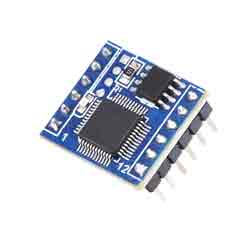
WS-TTL-CAN is a TTL UART to CAN module which is compact and easy to integrate, onboard high-performance MCU, with TTL and CAN conversion protocol, easily achieving UART to CAN via simple configuration.
Features
- Support the bidirectional data communication between CAN and TTL.
- The device parameters are configurable through TTL.
- ESD Protection, Anti-surge Protection, Excellent EMC Performance.
- 14 groups of configurable filters.
- Four operation modes: transparent conversion, transparent conversion with identifiers, format conversion, and Modbus RTU protocol conversion.
- Offline detection and automatic recovery functionality.
- Compliance with CAN 2.0B specifications, compatible with CAN 2.0A; complies with ISO 11898-1/2/3 standards.
- Baud rate range: 10kbps ~ 1000kbps.
- CAN buffer capacity of 1000 frames to prevent data loss.
- High-speed conversion: At a serial port baud rate of 115200 and CAN rate of 250kbps, the CAN sending speed can reach up to 1270 extended frames per second (close to the theoretical maximum of 1309). At a serial port baud rate of 460800 and CAN rate of 1000kbps, the CAN sending speed can exceed 5000 extended frames per second.
Parameters
| Model | TTL TO CAN Converter | |
| Host Interface | CAN | |
| Device Interface | TTL (RS485 direction control included) | |
| CAN Interface | Baud Rate | 10kbps~1000kbps |
| Direction Control | Hardware Automatic Control | |
| Resistor | Default 120R | |
| CAN Interface | CAN-H, CAN-L, GND | |
| TTL Interface | Baud Rate | 1200bps ~ 460800bps |
| Direction Control | Hardware Automatic Control | |
| TTL Interface | TXD, RXD, GND | |
| Button | Press 1 second | Reset the system |
| Press and hold for 5 seconds | Restore to the factory default | |
| Indicator | PWR | Red power indicator, lights up when the voltage is detected |
| RUN | Running status indicator, blinks at 1-second intervals when it is normally operated | |
| UART | CAN Red TX indicator, lights up when CAN sends data; TTL RX indicator, lights up when it receives data | |
| CAN | CAN RX indicator, lights up when CAN receives data; TTL TX indicator, lights up when TTL sends data | |
| Usage Environment | Temperature Range | -40~85℃ |
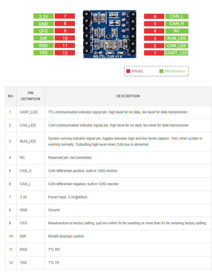
Pinout
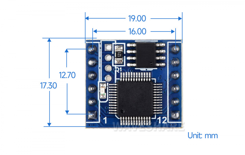
Dimensions
Device Configuration
Use USB TO TTL (or other USB to TTL devices) for initialization configuration. If you do not want to configure it, keep the factory setting.
Hardware Connection
- Connect the USB to TTL device (the following is for connecting USB TO TTL):
WS-TTL-CAN USB TO TTL GND GND RXD TXD TXD RXD
Software Operation
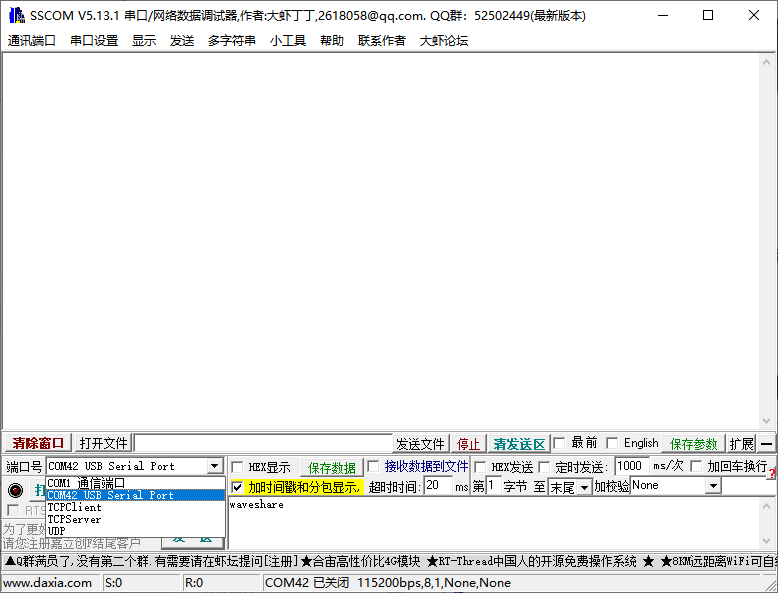
- Open SSCOM, view the used COM port, and demonstrate it with COM42:
- Open WS-CAN-TOOL

- Select the language:
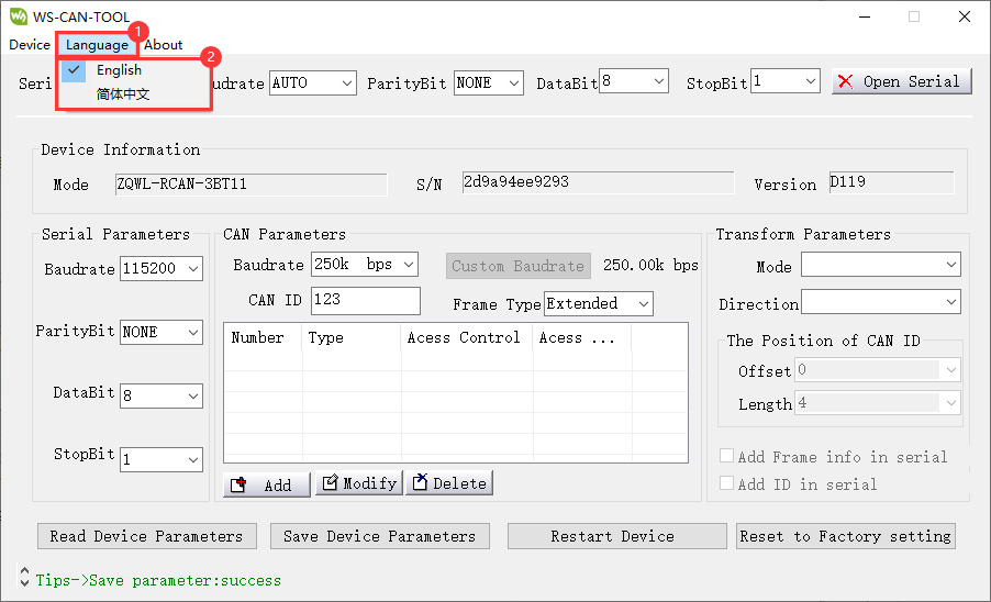
- Select the COM port corresponding to the connected RS232/485/422, and then open the serial port:
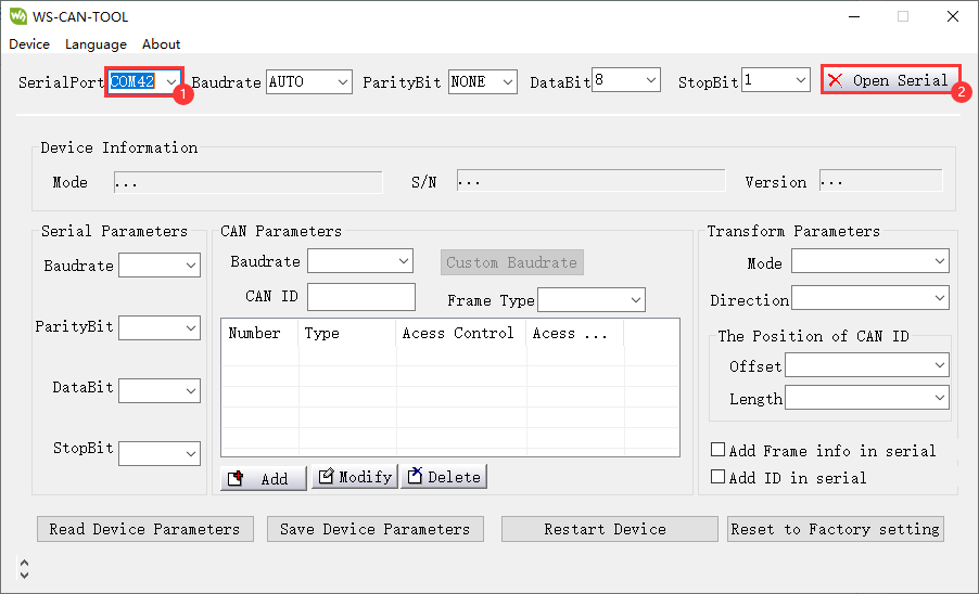
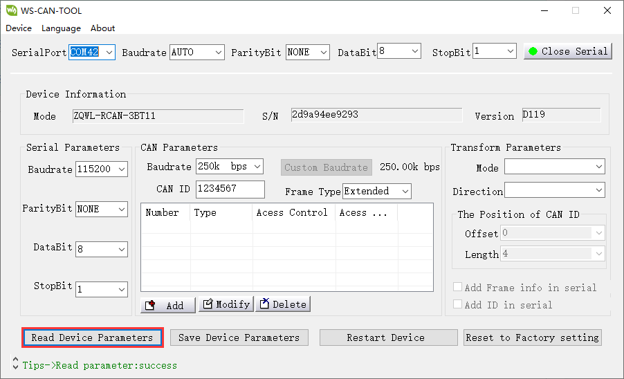
- Click on Read Device Parameters.
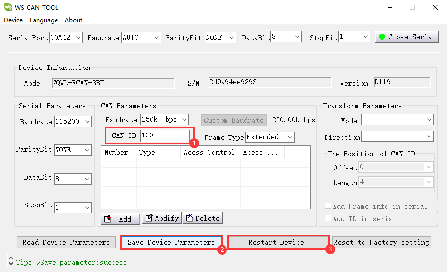
- If you need to modify the device parameters, you can directly modify it and click on "Save Device Parameters", and then click on "Restart Device" (for example, modifying CAN ID):
Module Usage Explanation
Transparent Conversion
*In this mode, the converter promptly sends the received data from one bus to the other bus.
USRT To CAN
- The entire data of a serial frame is sequentially filled into the data field of a CAN message frame. Upon receiving a frame of data from the serial bus, the converter promptly transmits it to the CAN bus. The converted CAN message frame information (frame type section) and frame ID are pre-configured by the user and remain unchanged throughout the conversion process.
- The format of the data conversion is illustrated in the diagram below.
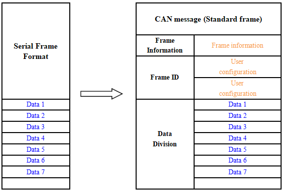
- If the length of the received serial frame is less than or equal to 8 bytes, characters from 1 to n (where "n" is the length of the serial frame) are sequentially filled into positions 1 to n in the data field of the CAN message (as depicted in the illustration where "n" is 7).
If the number of bytes in the serial frame is greater than 8, the processor starts from the first character of the serial frame and fills the first set of 8 characters sequentially into the data field of the CAN message. After transmitting this data onto the CAN bus, it proceeds to convert the remaining serial frame data and fills the CAN message's data field until all the data has been converted.
For example, in the CAN parameter settings, if "Standard Frame" is chosen and the CAN ID is filled with 00000060, note that only the last 11 bits are valid for standard frames. The converted CAN data appears as follows: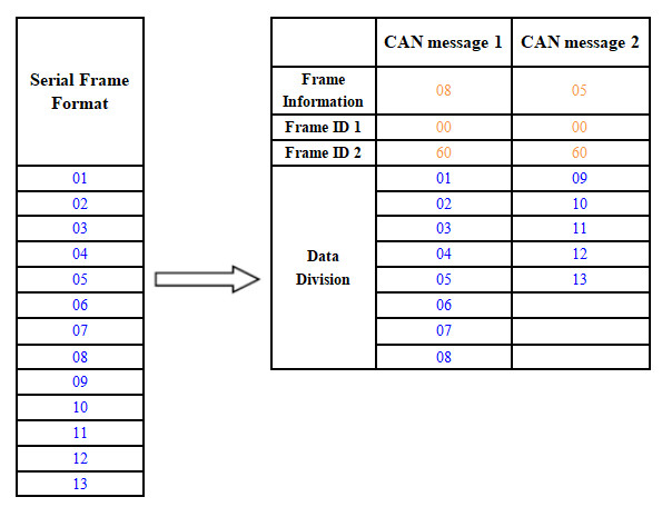
CAN Frame To UART
- For the CAN bus, it promptly sends a frame after receiving a frame.
- When converting, all the data in the CAN message field is converted to the serial frame in order, and the corresponding data format is shown below:
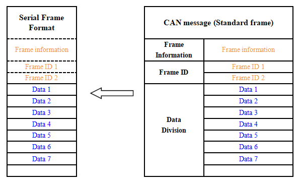
- If during configuration, the "Convert CAN Message to Serial" option is enabled, the converter will directly fill the "Frame Information" byte(s) of the CAN message into the serial frame. *Similarly, if the "Convert CAN Frame ID to Serial" option is enabled, it will fill all the "Frame ID" byte(s) of the CAN message into the serial frame.
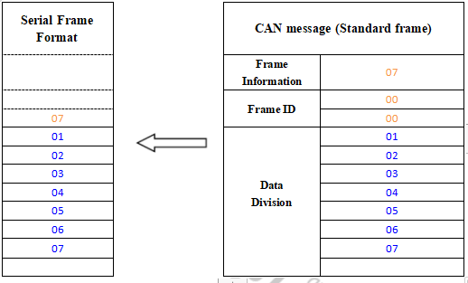
- For instance, if "Convert CAN Message to Serial" is enabled but "Convert CAN Frame ID to Serial" is not, the CAN frame converted to serial appears as illustrated below:
Transparent Conversion With ID
- Transparent conversion with ID is a specialized use of transparent conversion that facilitates users in constructing their networks more conveniently and employing custom application protocols.
- This method automatically converts the address information from a serial frame into the frame ID of the CAN bus. By informing the converter about the starting address and length of this address in the serial frame during configuration, the converter extracts this frame ID and converts it into the frame ID field of the CAN message. This serves as the ID of the CAN message when forwarding this serial frame. When converting a CAN message into a serial frame, the ID of the CAN message is also translated into the respective position within the serial frame. It's important to note that, in this conversion mode, the "CAN ID" setting in the "CAN Parameter Settings" of the configuration software is invalid. This is because, in this scenario, the transmitted identifier (frame ID) is populated from the data within the aforementioned serial frame.
UART to CAN
- Upon receiving a complete serial data frame, the converter promptly forwards it to the CAN bus.
- The CAN ID carried within the serial frame can be set within the configuration, specifying its starting address and length within the serial frame. The range for the starting address is from 0 to 7, while the length ranges from 1 to 2 for standard frames and 1 to 4 for extended frames.
- During conversion, based on the pre-configured settings, all CAN frame IDs within the serial frame are entirely translated into the frame ID field of the CAN message. If the number of frame IDs within the serial frame is fewer than the number of frame IDs within the CAN message, the remaining IDs within the CAN message are filled in the order of ID1 to ID4, with the remaining one filled with "0". The rest of the data undergoes sequential conversion as shown in the diagram.
- If a single CAN message frame does not complete the conversion of the serial frame data, the same ID continues to be used as the frame ID for the CAN message until the entire serial frame has been completely converted.
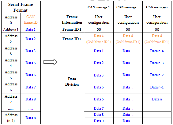
For example, the initial address of the CAN ID in the serial frame is 0, the length is 3 (in the extended frame), and the serial frame and the CAN message are as shown below. Note that the two frames of CAN messages are converted in the same ID.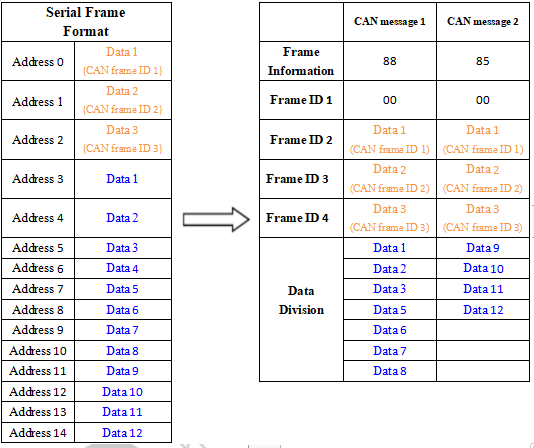
CAN Frame to UART
If the initial address of the configured CAN ID is 0 in the serial frame and a length of 3 (in the case of extended frames), the CAN message and the result of converting it to a serial frame are shown below: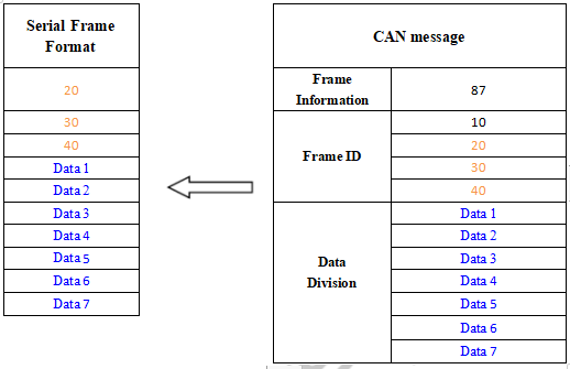
Format Conversion
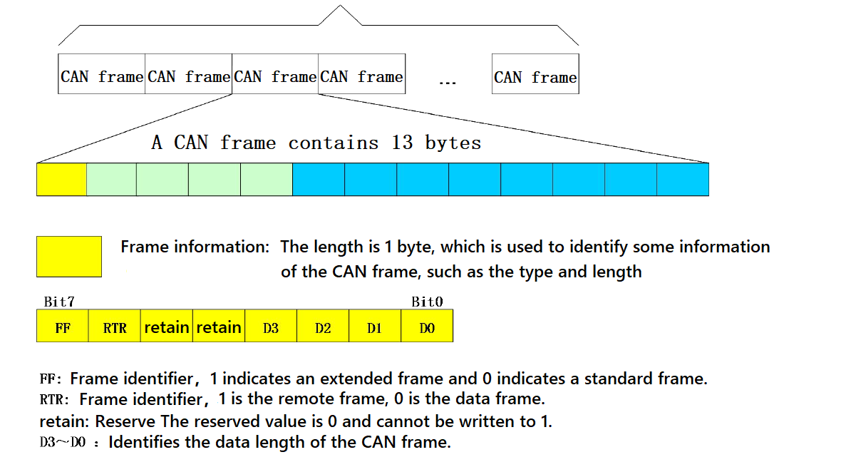
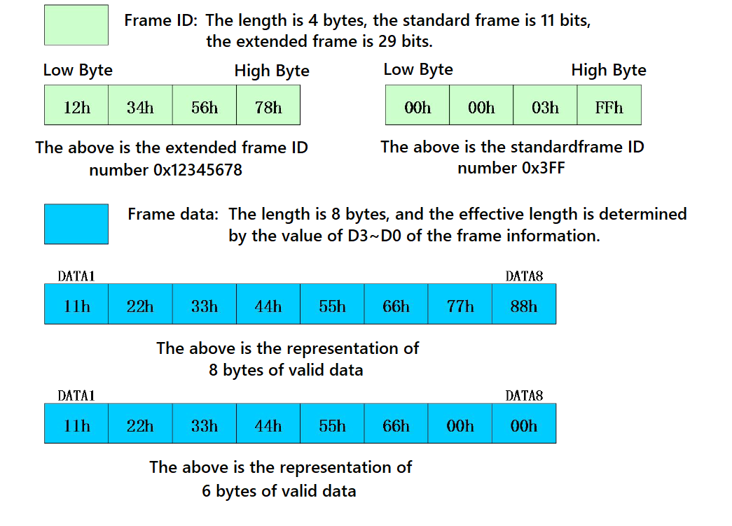
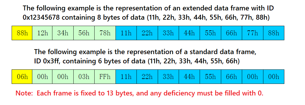
- This is the simplest mode of use and the data format is agreed to be 13 bytes, which contains all the information of the CAN frame.
Conversion Explanation
- Data conversion format as shown below. Each CAN frame includes 13 bytes, and they include CAN information + ID + data.
Modbus Protocol Conversion
*Convert the standard Modbus RTU serial data protocol to the specified CAN data format, and this conversion generally requires the editable CAN bus device message.
- The serial data must be compliant with the standard Modbus RTU protocol, otherwise it can not be converted. Please note that CRC parity can not be converted to CAN.
- The CAN formulates a simple and efficient segment communication format to realize Modbus RTU communication, which does not differentiate between host and slave, and users only need to communicate according to the standard Modbus RTU protocol.
- The CAN does not require CRC checksum, and after the converter receives the last CAN frame, the CRC will be added automatically. Then, a standard Modbus RTU data packet is formed and sent to the serial port.
- In this mode, the [CAN ID] of the [CAN Parameter Setting] of the configuration software is invalid, because the identifier (frame ID) sent at this time is filled by the address field (node ID) in the Modbus RTU serial frame.
Serial Frame Format (Modbus RTU)
- Serial parameter: baud rate, data bits, stop bits, and parity bits can be set via configuration software.
- The data protocol needs to conform to the standard Modbus RTU protocol.
CAN Frame Format
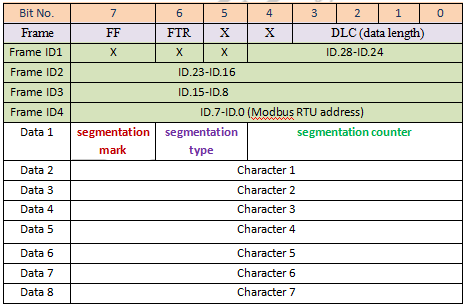
- The CAN side designs a set of segment protocol formats, which defines designed a segmentation protocol format that defines a method for segmenting and reorganizing a message that is greater than 8 bytes in length, as shown below.
- Note that when the CAN frame is a single frame, the segmentation flag bit is 0x00.
- The CAN frame message can be set by the configuration software (remote or data frame; standard or extended frame).
- The transmitted Modbus protocol starts from “Data 2” byte, if the protocol content is more than 7 bits, and the rest of the protocol content is converted in this segmented format until the conversion is complete.
- Data 1 is a segmentation control message (1 byte, 8bit), and the meaning is shown below:
Segmentation Mark
The segmentation mark occupies one bit (Bit7) and indicates whether the message is segmented or not. "0" indicates a separate message, and "1" indicates a frame in a segmented message.
Segmentation Type
The segmentation type occupies 2 Bits (Bit6, Bit5), and indicates the types of the report in this segment report.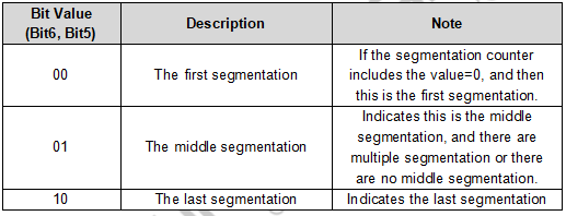
Segmentation Counter
Occupies 5 bits (Bit4-Bit0), used to distinguish the serial number of segments in the same frame Modbus message, enough to verify whether the segments of the same frame are complete.
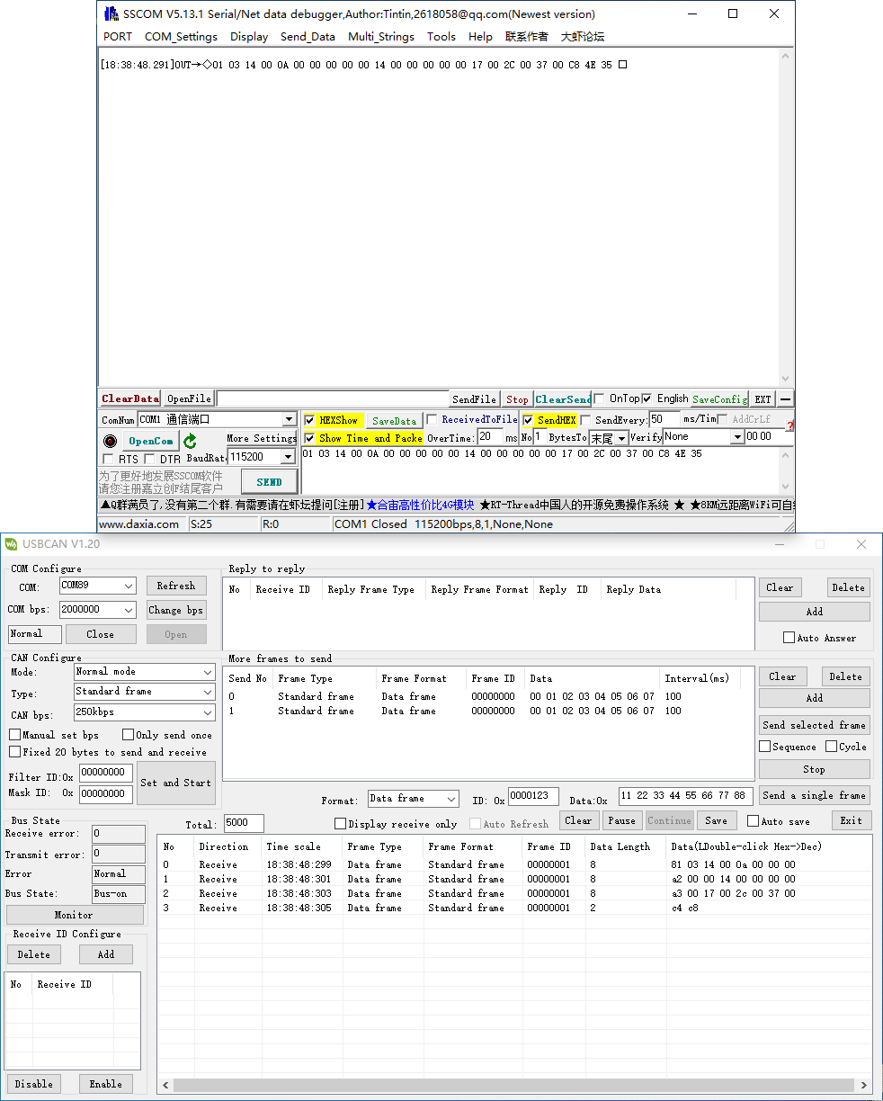
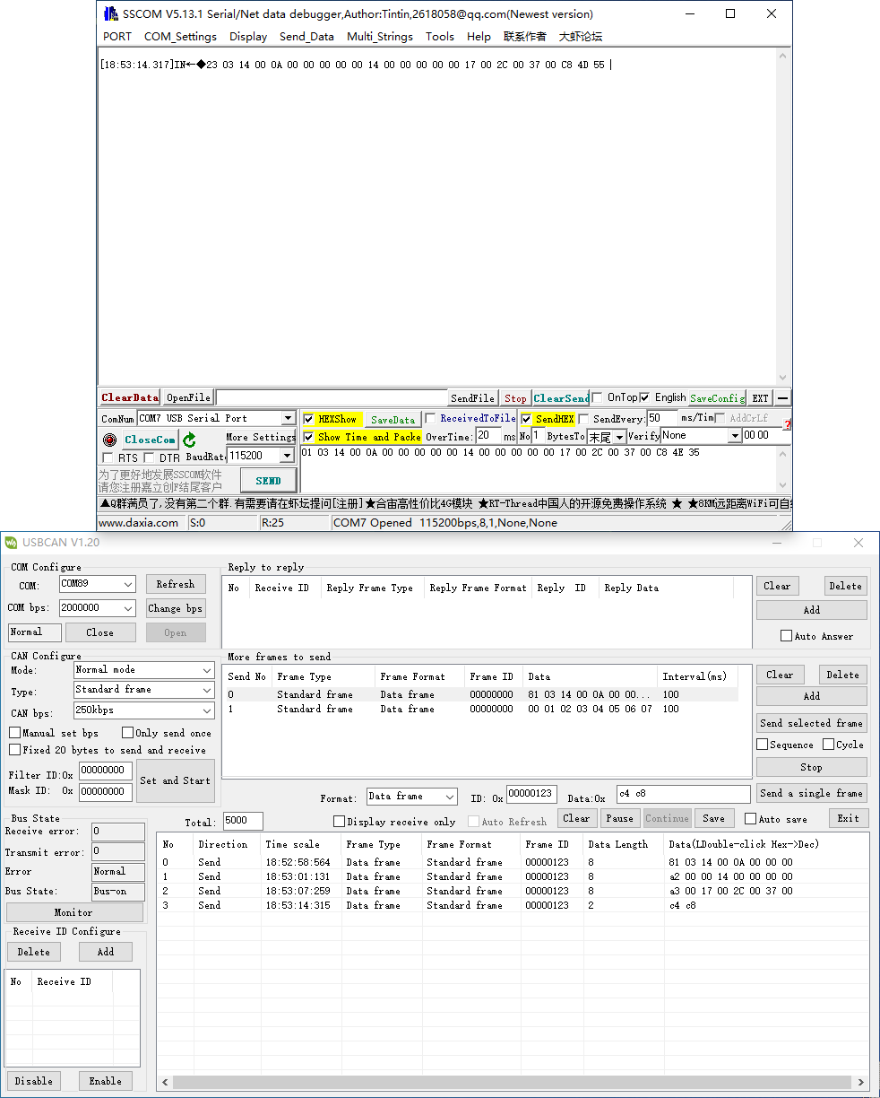
Conversion Example
- The serial port side Modbus RTU protocol (in hex).
- 01 03 14 00 0A 00 00 00 00 00 14 00 00 00 00 00 17 00 2C 00 37 00 C8 4E 35
- The first byte 01 is the Modbus RTU address code, converted to CAN ID.7-ID.0;
- The last 2 bytes (4E 35) are Modbus RTU CRC checksums, which are discarded and not converted.
- The final conversion to the CAN data message is as follows:
- Frame 1 CAN message: 81 03 14 00 0A 00 00 00 00
- Frame 2 CAN message: a2 00 00 14 00 00 00 00 00
- Frame 3 CAN message: a3 00 17 00 2C 00 37 00
- Frame 4 CAN message: c4 c8
- The frame type (standard or extended frame) of the CAN telegrams is set via the configuration software;
- The first data of each CAN message is filled with segmented information (81, a2, a3, and c4), which is not converted into Modbus RTU frames, but only serves as acknowledgment control information for the message.
- The conversion principle of data from the CAN side to ModBus RTU is the same as the above, after the CAN side receives the above four messages, the converter will combine the received CAN messages into a frame of RTU data according to the CAN segmentation mechanism mentioned above, and add CRC checksum at the end.
Verify Functions
TTL TO CAN Test
Use usb-can-a and USB TO TTL to demonstrate.
Hardware Connection
- Connect to CAN device:
WS-TTL-CAN - CAN USB-CAN-A CAN H CAN H CAN L CAN L
- Connect to TTL device
WS-TTL-CAN - TTL USB TO TTL GND GND RXD TXD TXD RXD
Software Operation
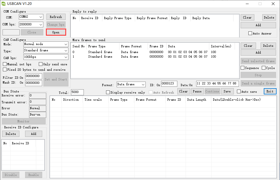
- Open USB-CAN-A-TOOL.
- Select the corresponding COM port of the USB-CAN-A, and click on "Open".
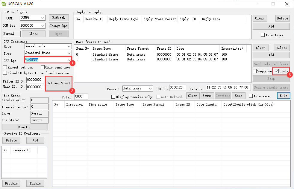
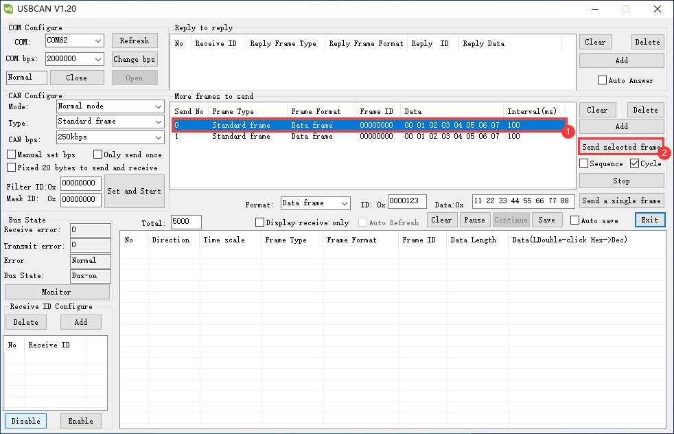
- Select the baud rate of the CAN device as 250kbps, click on "Send and start" , input the data to send, and select "Cycle".
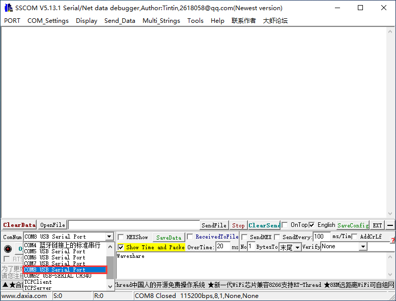
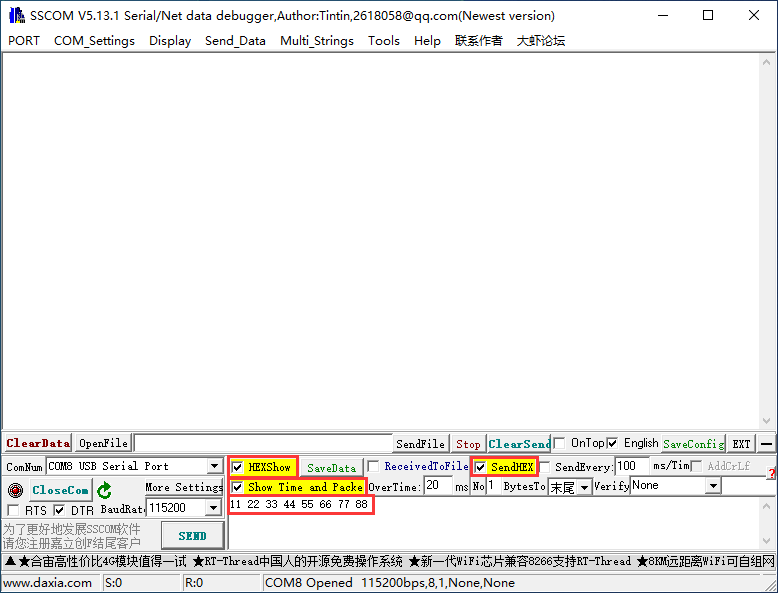
- Open an SSCOM, select the corresponding COM port of the USB TO 4CH Serial Converter's Port D, and open the serial port.
- In the SSCOM software, check Hexshow and show time and package, input the data to be sent.
11 22 33 44 55 66 77 88
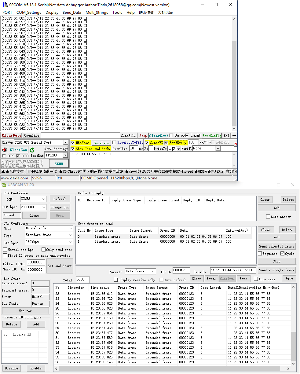
- Select data in USB-CAN-A_TOOL, click on "Send selected frame".
- And then you can see that it transmits and receives.
- Or you can click on "Send every...ms/Time".
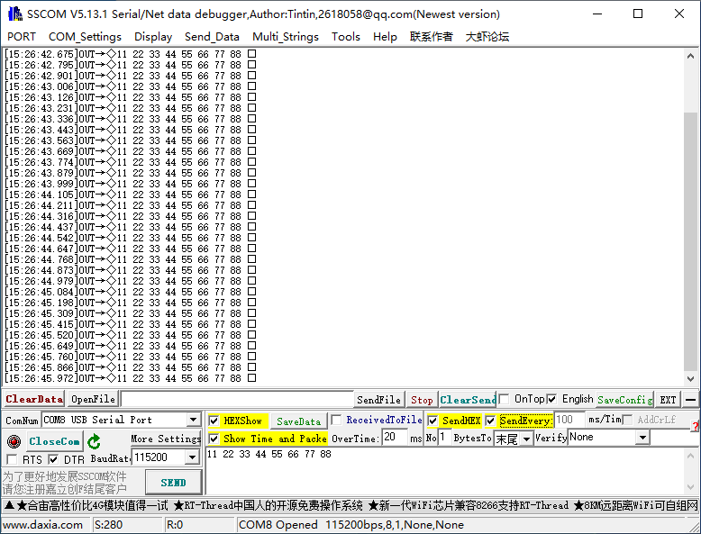
- And then you can see that it transmits and receives.
