


- sales/support
Google Chat: zj734465502@gmail.com
- sales
+86-0755-88291180
- sales01
sales01@spotpear.com
- sales02
dragon_manager@163.com
- support
services01@spotpear.com
- CEO-Complaints
manager01@spotpear.com
- sales/support
WhatsApp:13246739196
- HOME
- >
- ARTICLES
- >
- Common Moudle
- >
- ESP
ESP32-S3-GEEK Guide
Resource
Schematic
Demo
Development Software
Debugging Tool
- sscom serial port assistant
- NetAssist tool
- IOS Bluetooth assistant
- Android Bluetooth debugging tool
- Android TCP debugging tool
- Espressif APP
Datasheet
ESP32 Official Document
MicroPython Official Document
Overview
Introduction
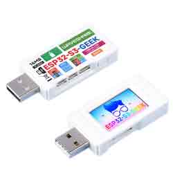
ESP32-S3-GEEK is a geek development board designed by Waveshare, onboard USB-A port, 1.14-inch LCD screen, a TF card slot, and other peripherals. Supports 2.4GHz WiFi and BLE 5, with integrated 16MB Flash & 2MB PSRAM, provides I2C port, UART port, and GPIO header, bringing more possibilities for your project.
Features
- Adopts ESP32-S3R2 chip with Xtensa® 32-bit LX7 dual-core processor, capable of running at 240 MHz.
- Built-in 512KB SRAM, 384KB ROM, 2MB of on-chip PSRAM, and onboard 16MB Flash memory.
- Onboard 1.14inch 240×135 pixels 65K color IPS LCD display.
- Integrated 2.4GHz WiFi and Bluetooth LE wireless communication.
- WiFi supports Infrastructure BSS in Station, SoftAP, and Station + SoftAP modes.
- WiFi supports 1T1R mode with a data rate of up to 150 Mbps.
- Bluetooth supports high power mode (20dBm).
- Internal co-existence mechanism between Wi-Fi and Bluetooth to share the same antenna.
- The onboard 3-pin UART interface can function as a USB-to-serial adapter.
- The onboard 3-pin GPIO interface can be used for debugging other modules or for ADC data collection.
- The onboard 4-pin I2C interface is available for testing the target board.
- Equipped with plastic case and cables.
- Provides online open-source demos and resources, more convenient for learning and development.
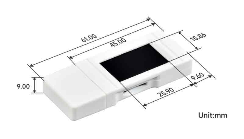
Dimensions
Development Environment Configuration
- The following development system is Windows by default.
ESP-IDF
- It is recommended to develop with the VSC plug-in.
Develop with VSCode
Install VSCode
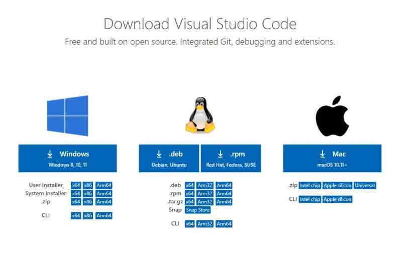
- 1. Open the download page of the official VSCode website, and select the corresponding system and system bit to download.
- 2. After running the installation package, the rest can be installed by default, but here for the subsequent experience is recommended, it is recommended to check boxes 1, 2, and 3 here.
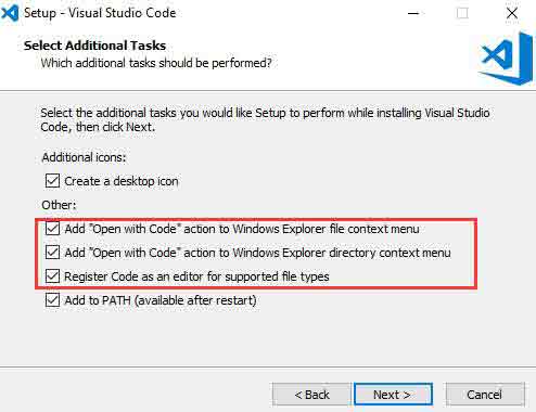
- After the first two items are enabled, you can open VSCode directly by right-clicking files or directories, which can improve the subsequent user experience.
- After the third item is enabled, you can select VSCode directly when you choose how to open it.
Install Espressif IDF Plug-in
- Note: The latest version of the current plug-in is V1.6.0, for a consistent experience, users can choose the same version as us.
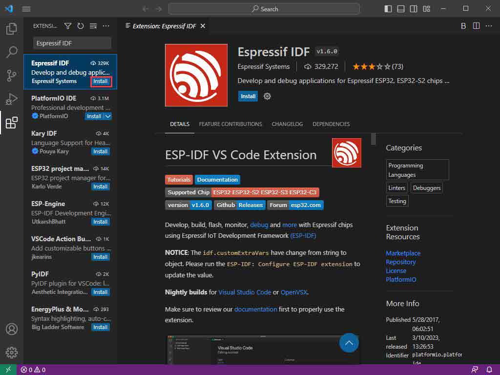
- 1. Open VSCode and use the shortcut key Shift + Ctrl + X to enter the plugin manager.
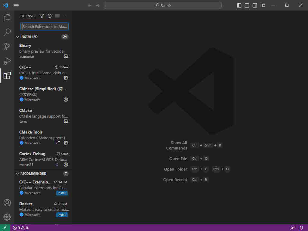
- 2. In the search bar, type Espressif IDF, select the corresponding plug-in, and click install.
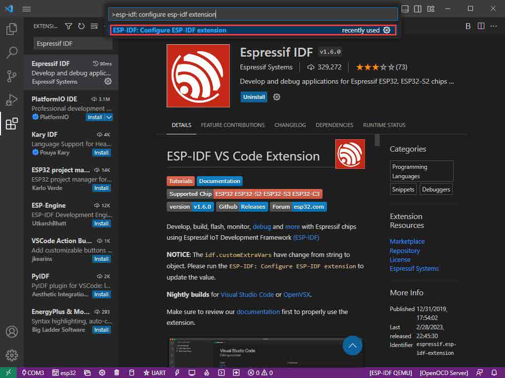
- 3. Press F1 to enter:
esp-idf: configure esp-idf extension
- 4. Choose express (This tutorial is for users who install it for the first time, so only the first general installation tutorial is covered.)
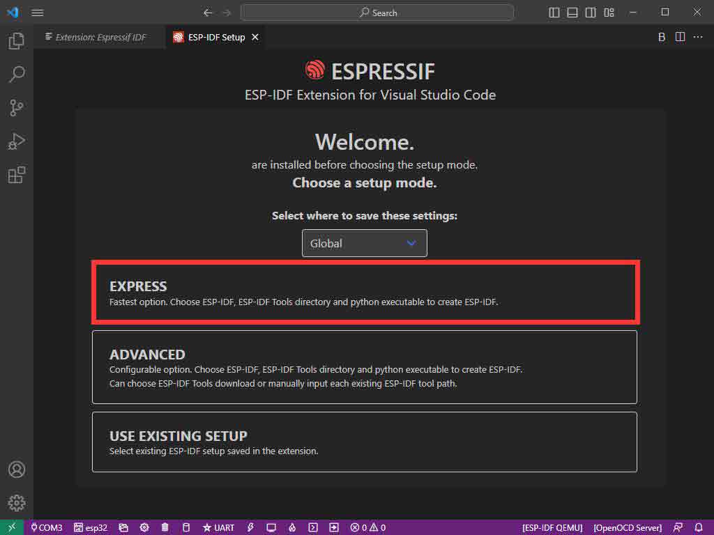
- 5. Open and display this screen.
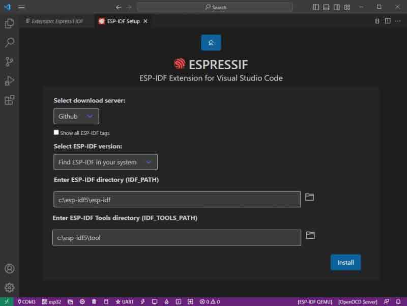
- 6. Choose a server to download.
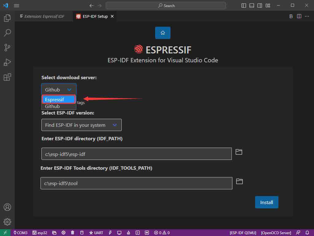
- 7. Select the ESP-IDF version you want now, we choose the latest V5.0.1 (note that ESP-IDF started to support ESP32-S3 only after V4.4).
- 8. The following two are the ESP-IDF directory installation address and the ESP-IDF required tools installation address respectively.
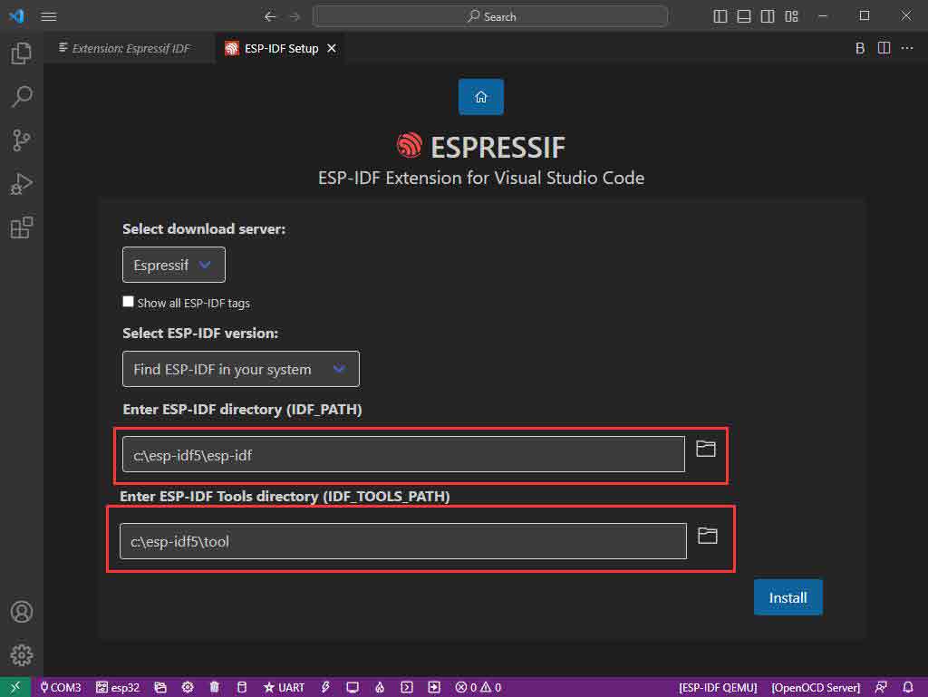
- Note: If you have installed ESP-IDF before, or if it has failed, please make sure to delete the file completely or create a new path.
- 9. Once the configuration is finished, click "install" to download.
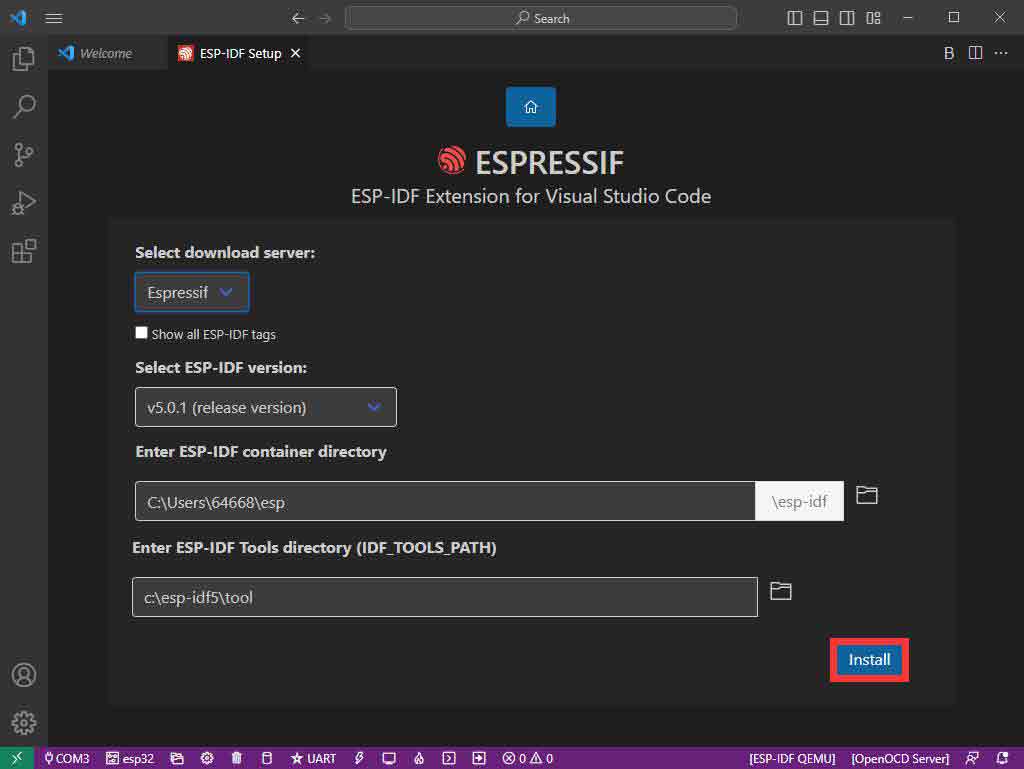
- 10. Enter the download page, it will automatically install the corresponding tools and environment, just wait a moment.
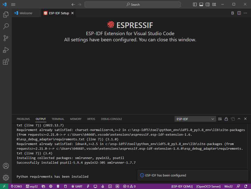
- 11. After the installation is completed, it will enter the following screen, indicating that the installation is finished.
- Official Demo Usage
- Click here to view more details provided by the official ESP.
Creating a Demo
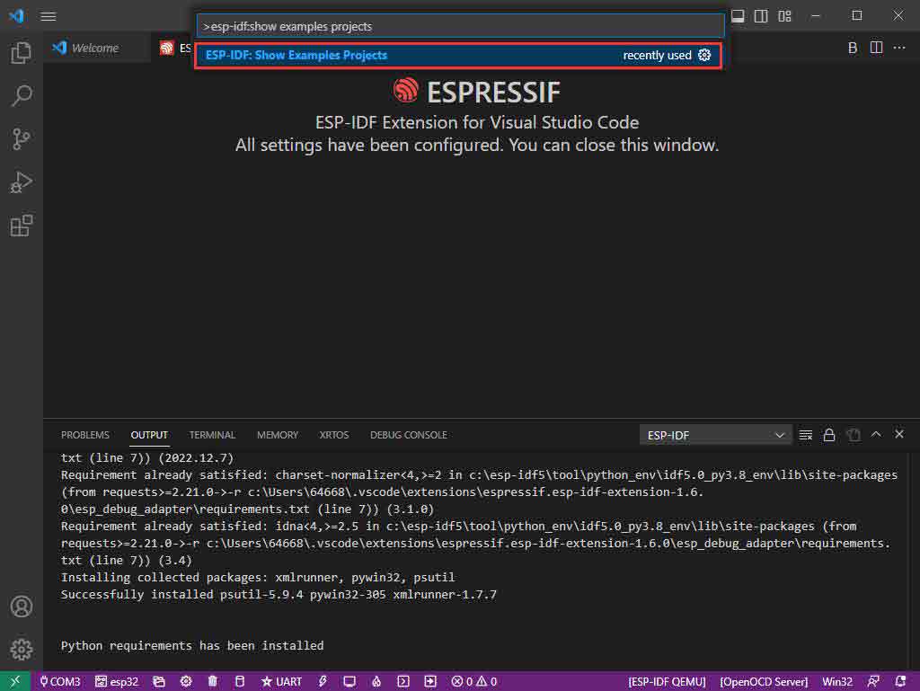
- 1. Using the shortcut F1, type:
esp-idf:show examples projects
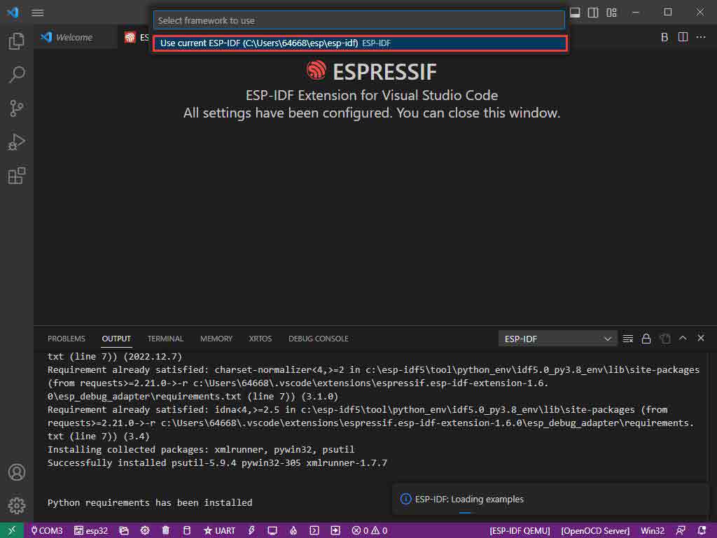
- 2. Choose your current IDF version:
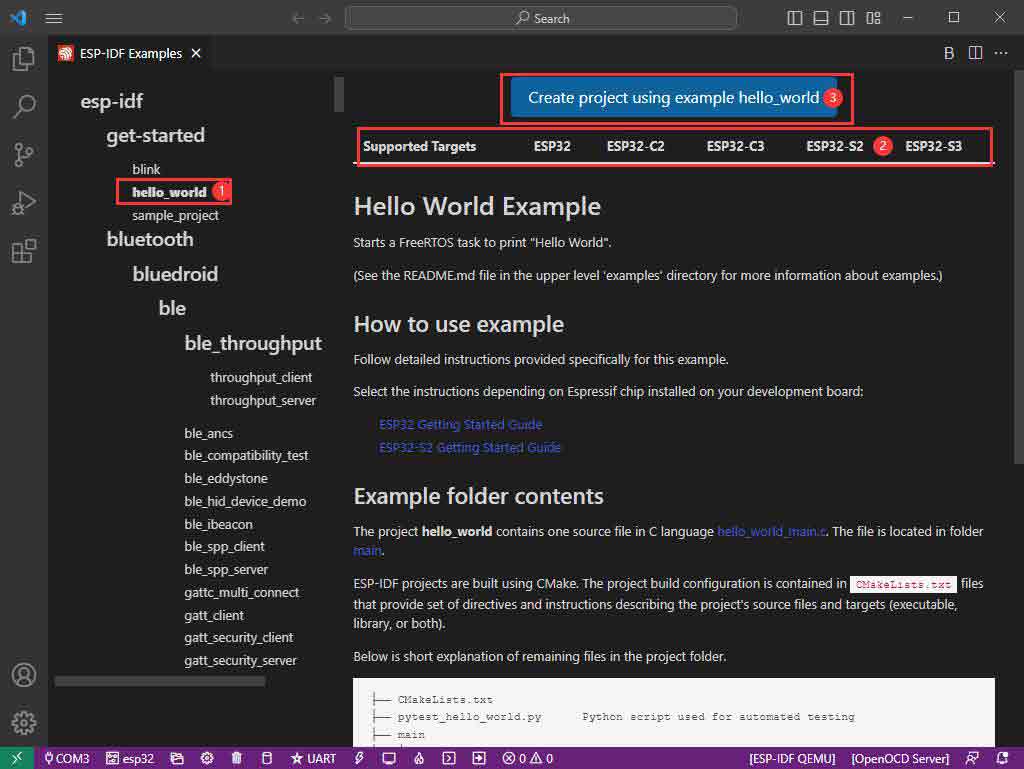
- 3. Take "Hello World" as an example:
- 4. ① Choose the corresponding demo.
- 5. ② The readme file will explain which chip the demo is suitable for (the following section will introduce how to use the demo and its file structure, which is omitted here).
- 6. ③ Click to create the demo.
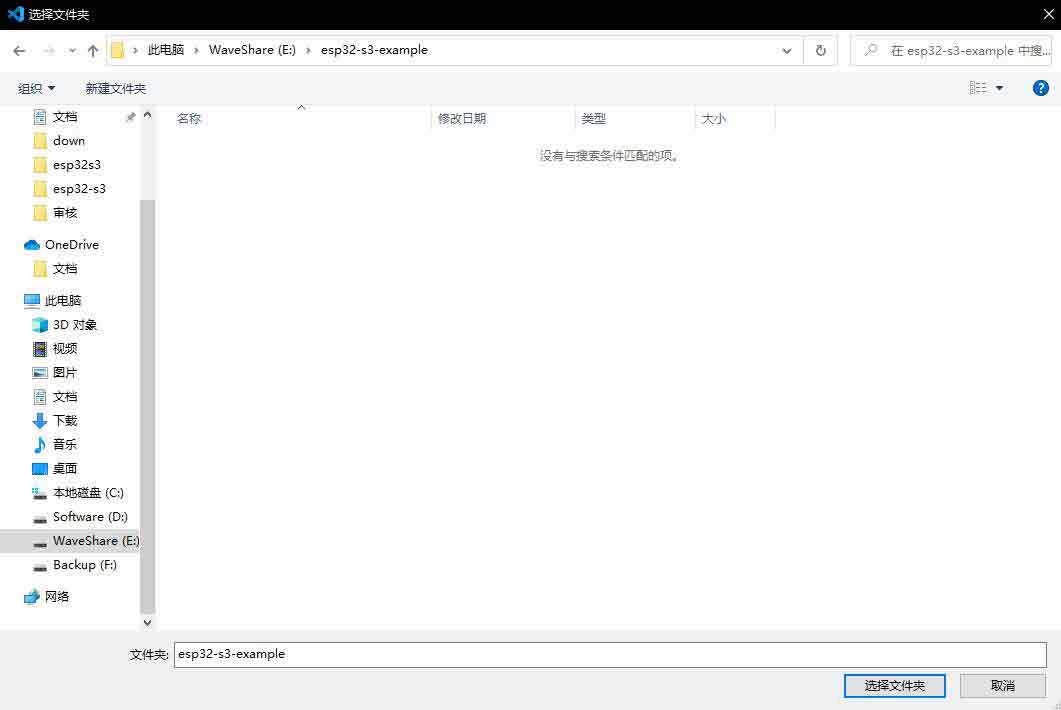
- 7. Choose the path to place the demo and ensure that there is no folder with the same name as the demo.
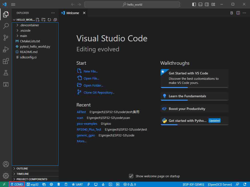
- Modify COM Port
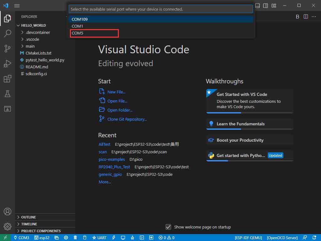
- 1. The corresponding COM port is displayed here, click on it to modify.
- 2. The COM port of our CH343 is COM5, so we choose COM5, please choose the COM port according to your CH343.
- 3. Choose the project and demo.
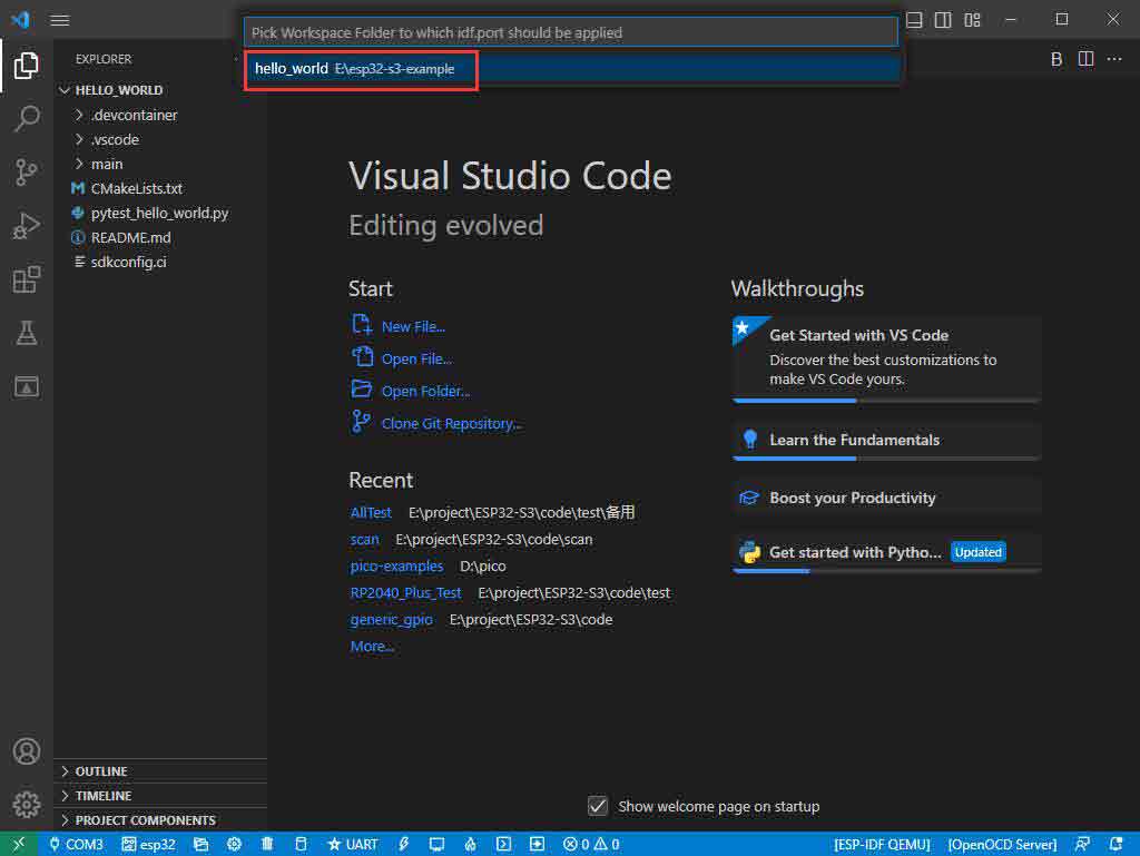
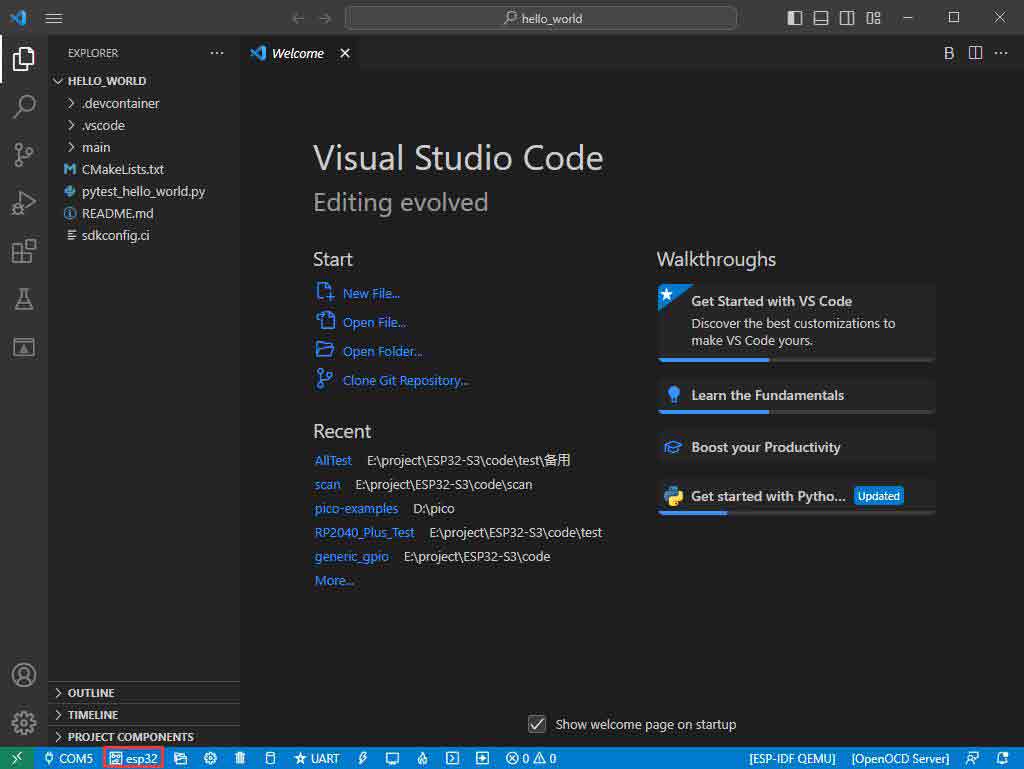
- 4. Then the COM port is modified.
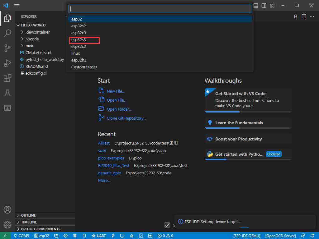
Modify the Driver
- 1. Here shows the driver used, click here to modify the corresponding driver:
- 2. Choose the project or demo:

- 3. Wait for a few seconds after clicking.
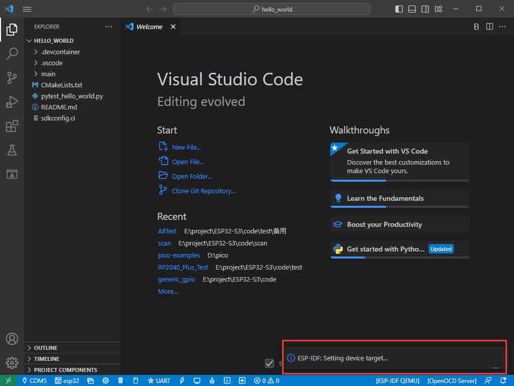
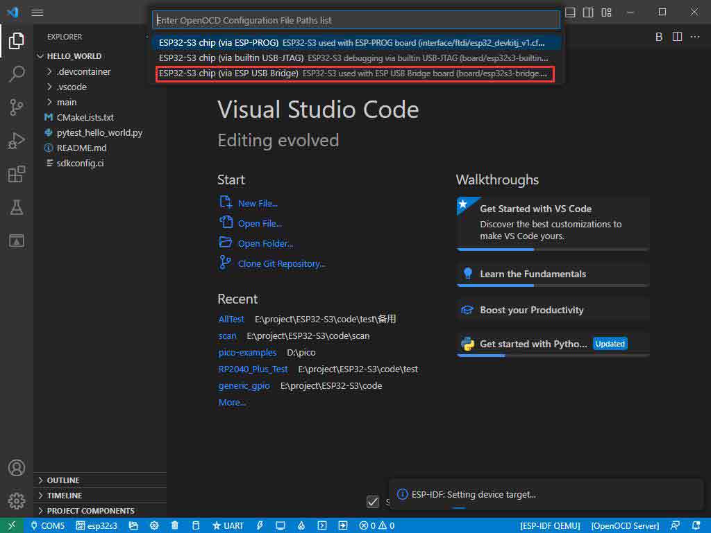
- 4. Choose the driver we need, that is, the main chip ESP32S3.
- 5. Choose the openocd path, we can just choose one as it doesn't matter.
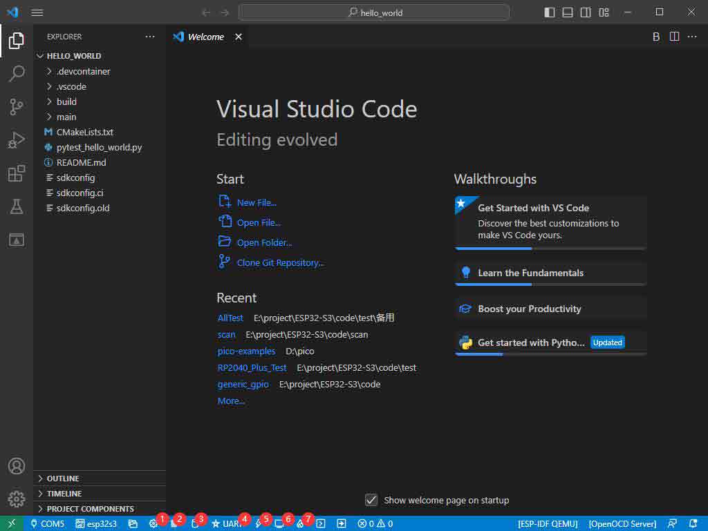
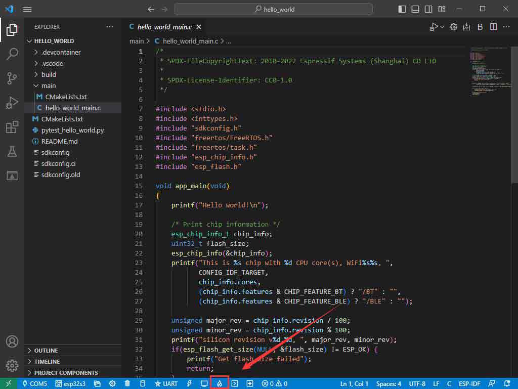
- The Rest of the Status Bar Introduction
- ① SDK configuration editor: many functions and configurations of ESP-IDF can be modified within it.
- ② Clean up everything and delete all compiled files.
- ③ Compile.
- ④ Current download method, default is UART.
- ⑤ Program the current firmware, please do it after compiling.
- ⑥ Open the serial monitor to view serial information.
- ⑦ Combined button for compiling, programming, and opening the serial monitor (most commonly used during debugging).
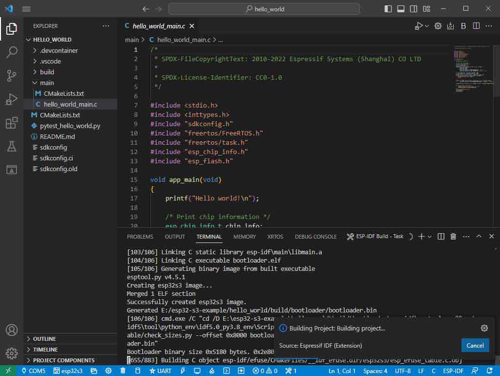
Compile, Program, and Serial Port Monitoring
- 1. Click on the Compile, Program, and Open Serial Monitor buttons we described earlier.
- 2. It may take a long time to compile, especially for the first time.
- During this process, ESP-IDF may take up a lot of CPU resources and therefore may cause system lag.
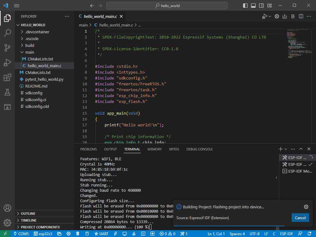
- 3. Because we use CH343 as the USB to serial chip, and the onboard auto-download circuit, it can download automatically without manual operation.
- 4. After successful download, it will automatically enter the serial monitor, you can see the corresponding information output from the chip and prompt to reboot after 10s.
Arduino
- If you do not use arduino-esp32 before, you can refer to this link.
Install Arduino
- 1. Open the official software download webpage, and choose the corresponding system and system bits to download.
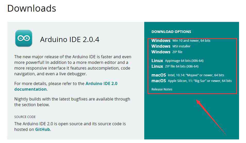
- 2. You can choose "Just Download", or "Contribute & Download".

- 3. Run to install the program and install it all by default.
Install arduino-esp32
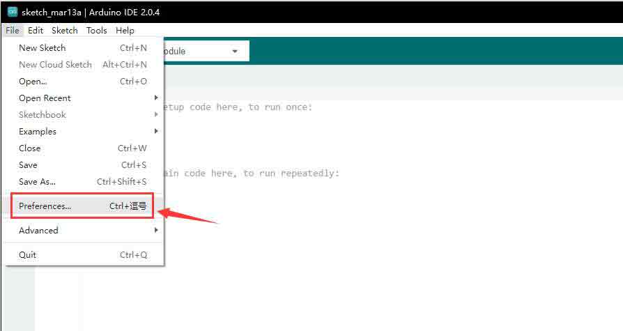
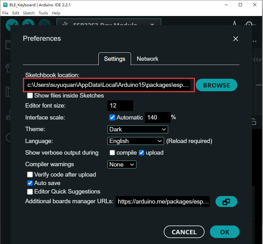
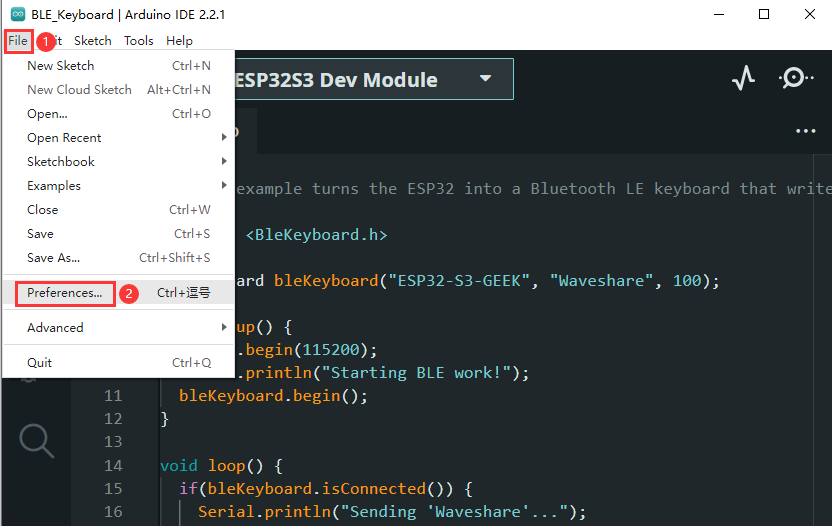
- 1. Open Preferences.
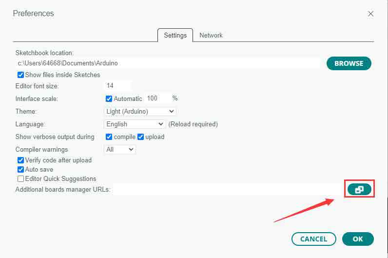
- 2. Add the corresponding board manager URLs and click it.
- 3. Add the following content in the blank.
https://raw.githubusercontent.com/espressif/arduino-esp32/gh-pages/package_esp32_index.json
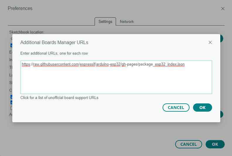
- 4. Save the setting.
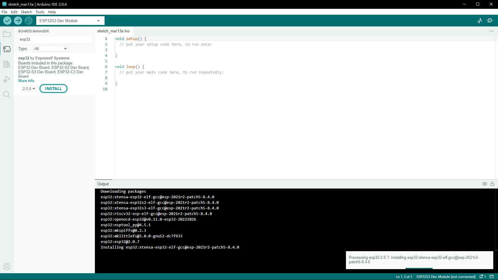
- 5. Open the board manager and enter ESP32 in the search bar.
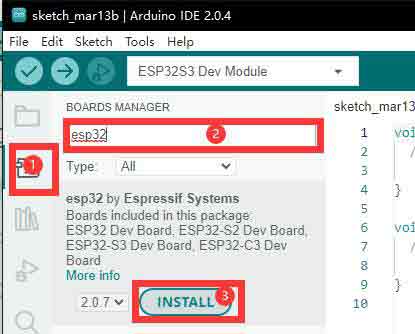
- 6. Wait for downloading.
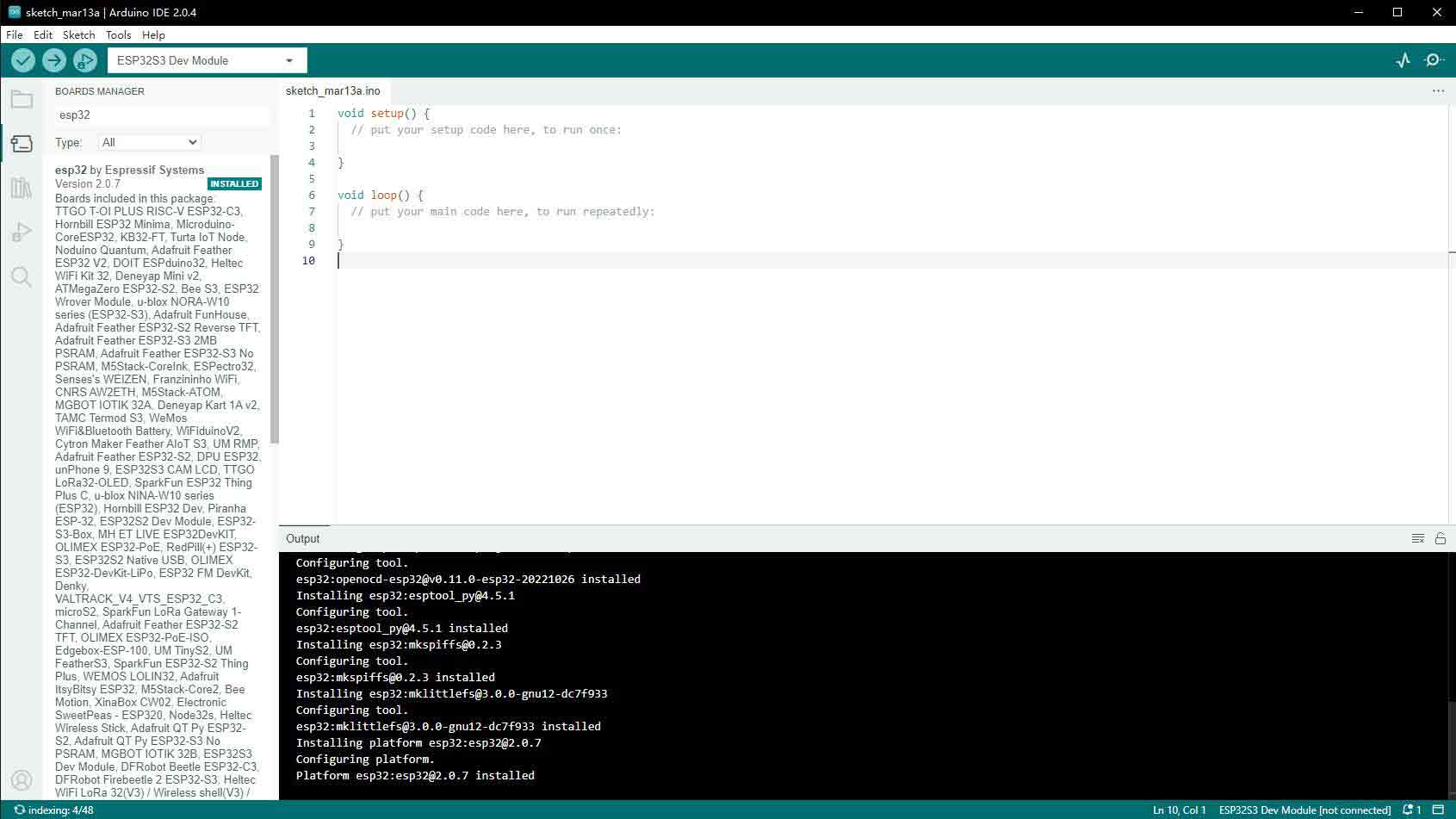
- 7. arduino-esp32 is downloaded.
Use Arduino Demo
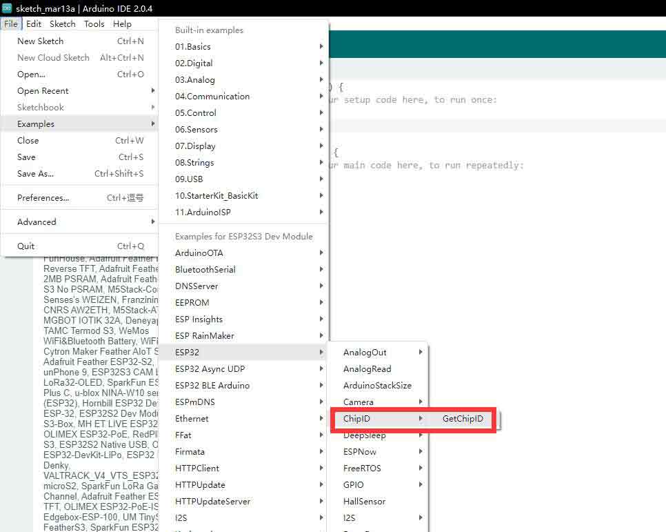
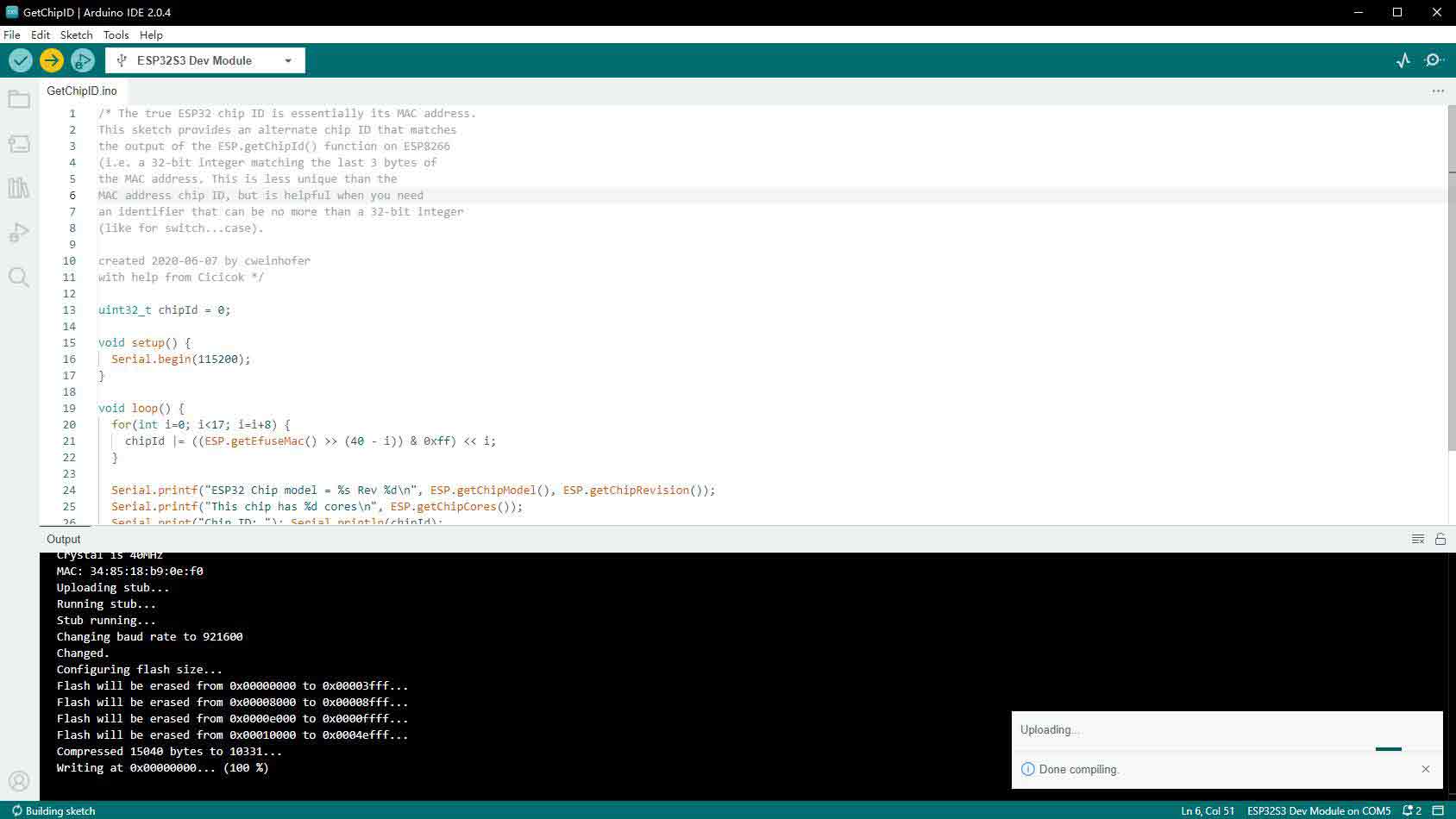
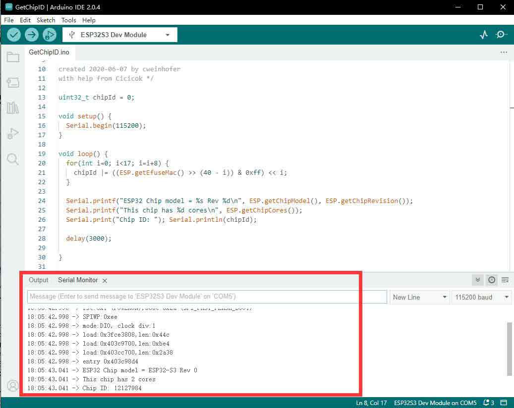
- 1. Select the demo, here we choose the demo to get the chip ID.
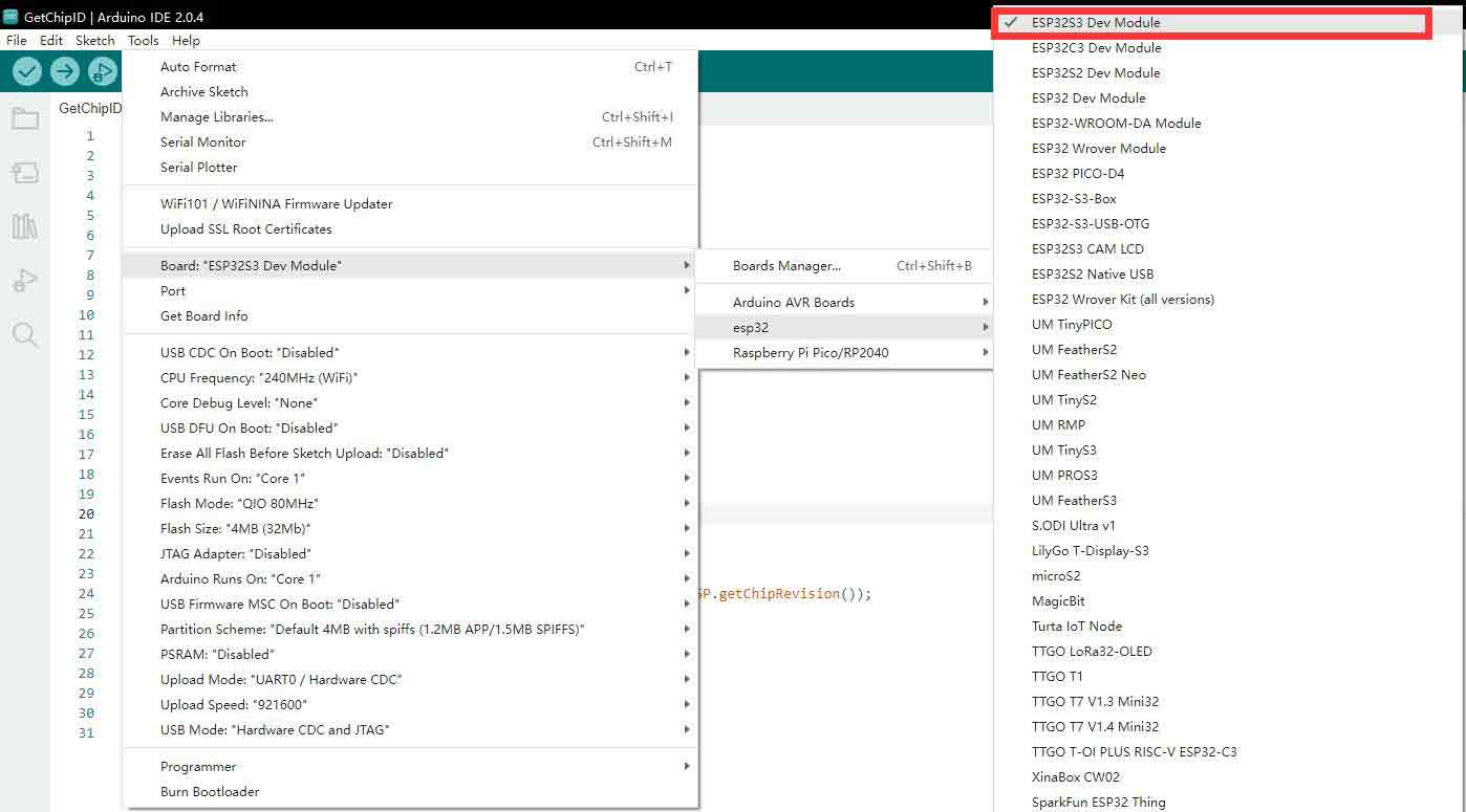
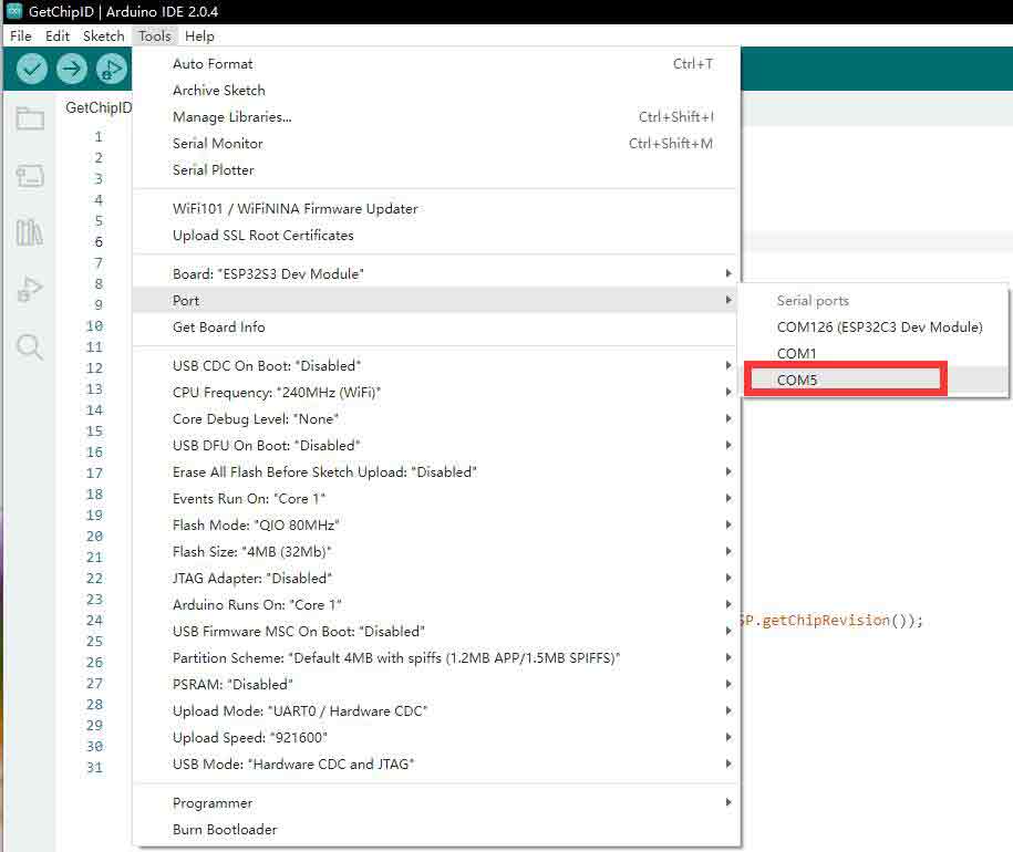
- 2. Select the board as ESP32S3 Dev Module.
- 3. Choose the COM5 port of CH343.
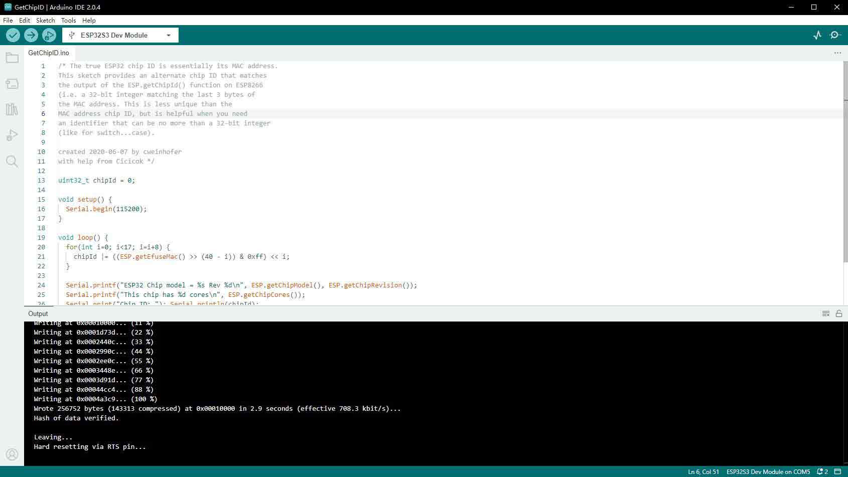
- 4. Click the download button, then it compiles and downloads automatically.
- 5. Finish.
- 6. Open the Serial Port Monitor.
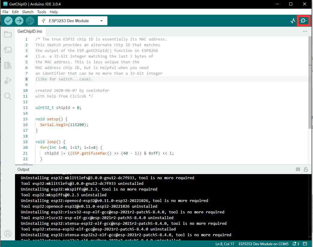
- 7. See the chip ID of the loop output.
Sample Demo
WIFI
01-WIFI_AP_LCD
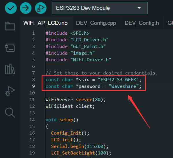
This code enables ESP32-S3-GEEK to open an Access Point (AP) mode for Wi-Fi. Once a PC is connected to its Wi-Fi network, you can log in to its IP address via a web interface to control the display of images on ESP32-S3-GEEK's LCD.
- "ssid" is the AP name (ESP32-S3-GEEK) created by ESP32-S3-GEEK, and the "password" is the password (Waveshare) for connecting to AP.
- Connect to the AP of the ESP32-S3-GEEK Demo on the PC, and enter the password "Waveshare".
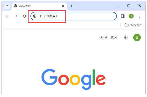
- The LCD will display the IP address of the HTTP server, and you can use the browser to log in the IP: 192.168.4.1.
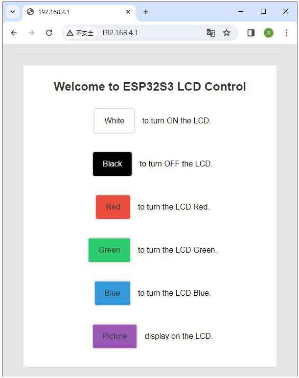
- Control the LCD of the ESP32-S3-GEEK through the button on the server, and you can observe the LCD by clicking on different buttons. For LCD function, you can refer to LCD demo description.
02-WIFI_TCP_Client
With this demo, ESP32-S3-GEEK enters WIFI's STA mode and connects to the same WIFI as the PC or mobile phone. As TCP Client accesses the TCP Server created by the PC or mobile phone, TCP communication is established, and the LCD displays the received content.
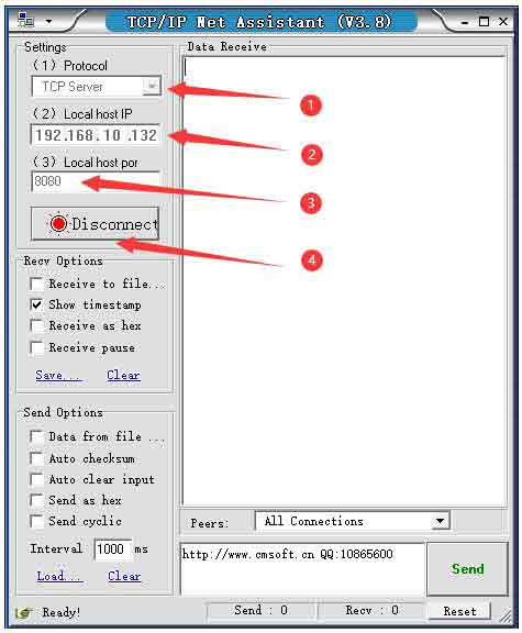
Using NetAssist.exe to enter the TCP Server, the Local host IP is the default one, and the Local host Port is 8080. Click on "Connect" for TCP communication with ESP32-S3-GEEK(TCP Client).
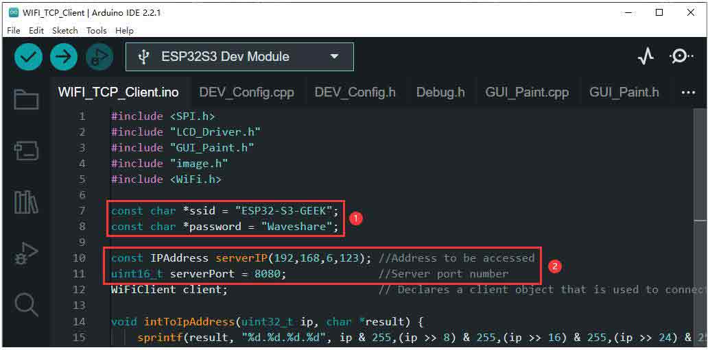
- The ESP32-S3-GEEK connects to the same WIFI network as the PC in STA mode. The WIFI network that ESP32-S3-GEEK connects to should operate on the 2.4GHz frequency band. If there's no 2.4GHz frequency band available, the PC can create a hotspot with the network band set to "Any available frequency." Remember to change the SSID and password to match the WIFI name and password you wish to connect to.
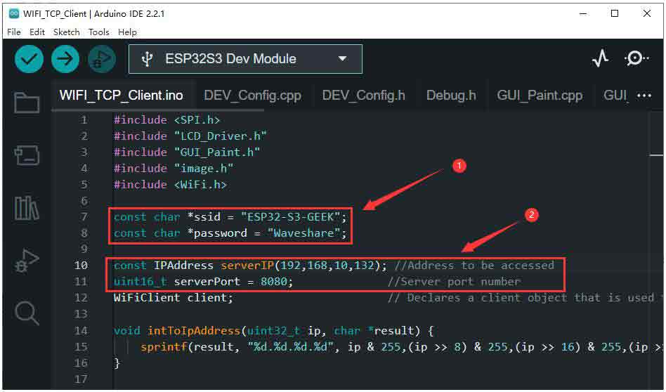
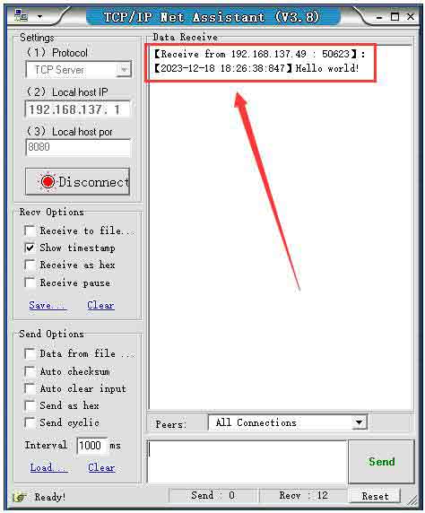
- Modify the serverIP to the TCP Server's IP address obtained from using NetAssist.exe, and keep the serverPort as 8080. Upon successful connection, the ESP32-S3-GEEK will send a TCP message "Hello world" to the TCP Server, and the LCD will display "Access successful".
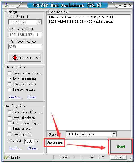
- TCP Server sends the TCP message to the ESP32-S3-GEEK on the PC. If sent successfully, ESP32-S3-GEEK as the TCP Client can receive the message and display it on the LCD, and you can observe whether the LCD displays the message.
- You can also use your phone to create a hotspot with the name (SSID) and password as "ssid" and "password", respectively, operating on the 2.4GHz frequency band. After setting up the hotspot, you can use a TCP debugging tool to establish TCP communication with ESP32-S3-GEEK.
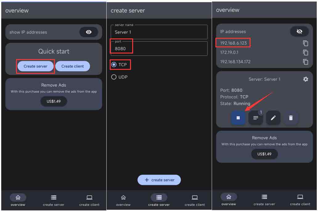
- Modify the WIFI connected by the code as the hotspot of the smartphone, serverIP is the IP (192.168.6.123) of the TCPserver created by the smartphone in the above picture.
- After programming the demo, once connected, the TCP Server will receive a TCP message "Hello world" from ESP32-S3-GEEK. The LCD will display "Access successful". Using a mobile device's TCP Server, you can send TCP messages to ESP32-S3-GEEK. If the transmission is successful, ESP32-S3-GEEK, acting as a TCP Client, will receive the message and display its content on the LCD. This allows you to observe whether the LCD shows the message.
03-WIFI_TCP_Server
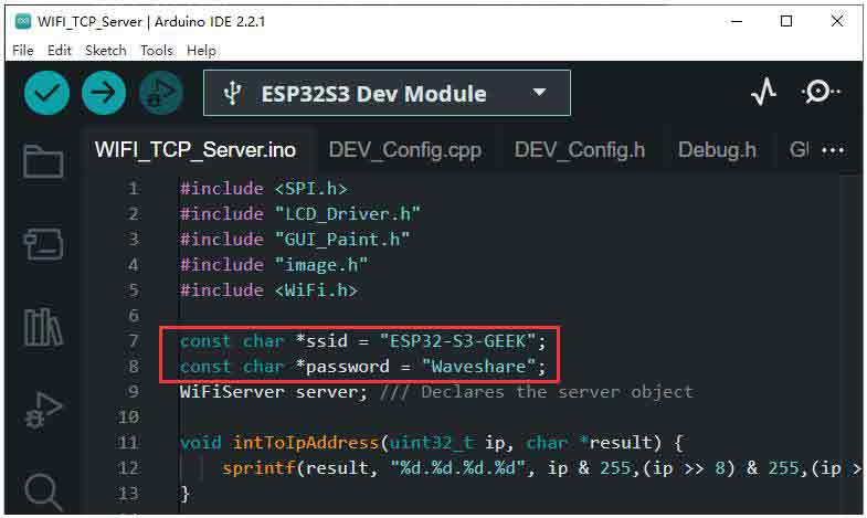
With this demo, ESP32-S3-GEEK enters WIFI's STA mode. After connecting the hotspot on the PC, creates a TCP Server, and the PC creates a TCP Client to access ESP-S3-GEEK. Then, the TCP communication is established between them, and GEEK displays the received content on the LCD.
- ESP32-S3-GEEK connect the same WIFI on the STA mode. (The WIFI network that ESP32-S3-GEEK connects to should operate on the 2.4GHz frequency band. If there's no 2.4GHz frequency band available, the PC can create a hotspot with the network band set to "Any available frequency." Remember to change the SSID and password to match the WIFI name and password you wish to connect to.)
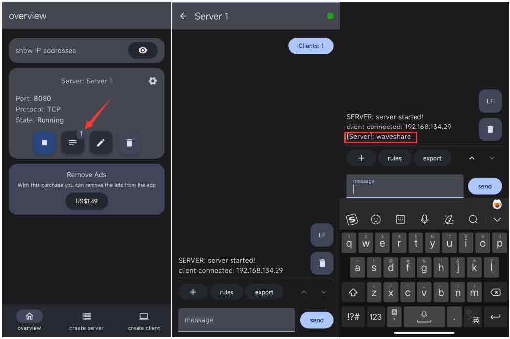
- After connecting to the WIFI, the LCD will display TCP ServerIP, and use SSCOM to open TCP Client for ESP32-S3-GEEK(TCP Server) connection with TCP.
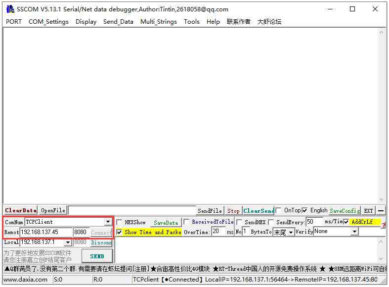
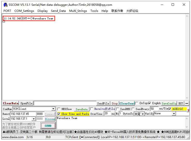
- Sending TCP message through TCP Client to ESP32-S3-GEEK(TCP Server), checking the "Carriage Return" and "Line Feed" options while sending the message.
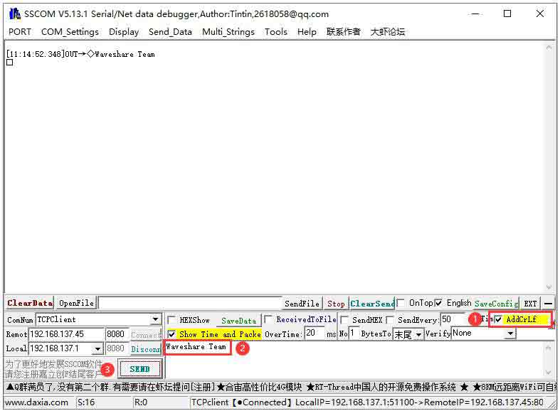
- After sending successfully, ESP32-S3-GEEK as the TCP server receives the message and displays it on the LCD, and you can check whether the LCD displays the received message.
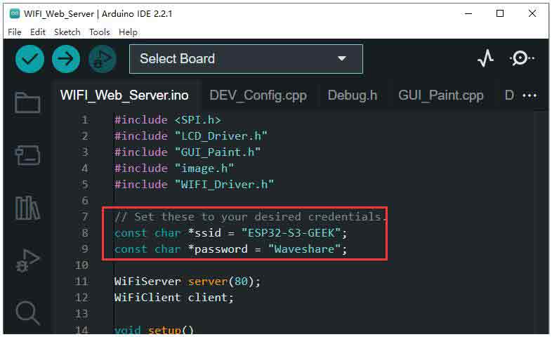
04-WIFI_Web_Server
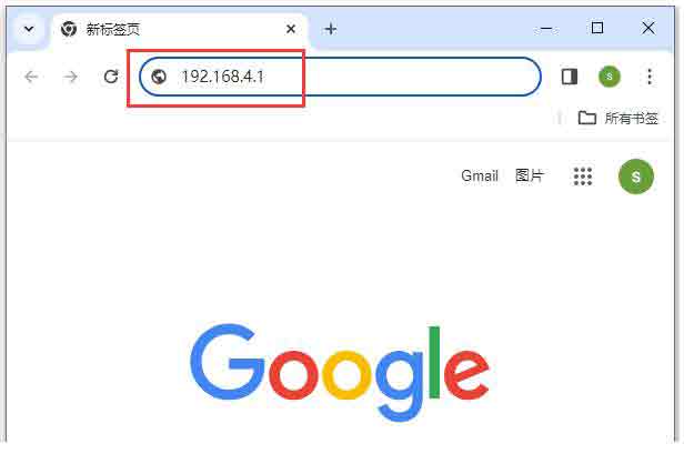
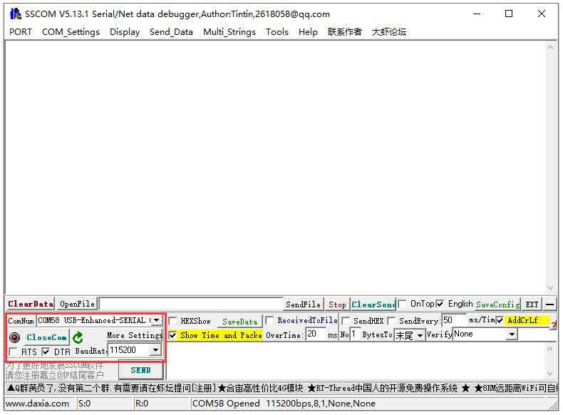
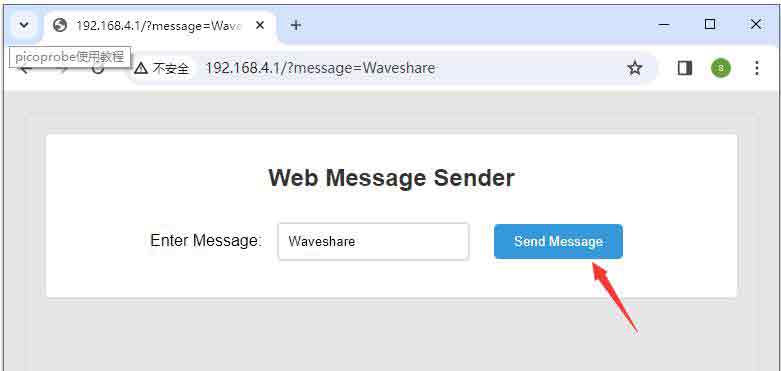
This code allows the ESP32-S3-GEEK to open its WIFI in AP mode. After a PC connects to this WIFI, open a serial debugging assistant. Through the HTTP webpage created by the ESP32-S3-GEEK, messages can be sent to the GEEK. Observe the received content on both the serial debugging assistant and the LCD.
- The "ssid" is the name of the WIFI network created by the ESP32-S3-GEEK, and the "password" is the password required to connect to this network.
- Using the PC to connect to the AP of the ESP32-S3-GEEK.
- The LCD will display the HTTP server's IP address. Use a web browser to log in to the IP address: 192.168.4.1.
- Using the ESP32-S3-GEEK's UART interface, connect it to the PC via a USB to UART tool, then open a serial debugging assistant.
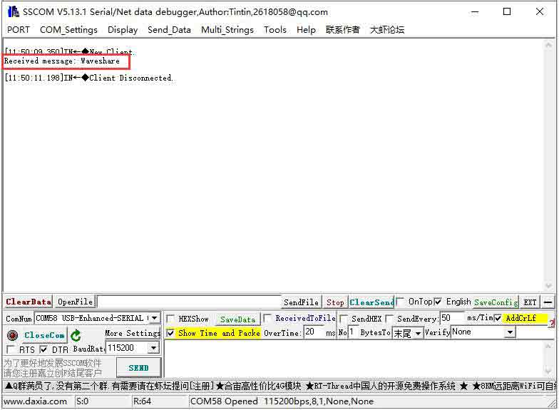
- You can input text content on the HTTP web interface and send an HTTP request to the ESP32-S3-GEEK. The received content can be displayed on both the serial debugging assistant and the LCD.
BLE
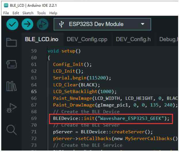
01-BLE_LCD
With this demo, ESP32-S3-GEEK enters BLE. Using a mobile phone to open the Bluetooth debugging assistant, connect to ESP32-S3-GEEK, and establish BLE communication with the mobile phone. The message of sending and receiving is displayed on the LCD.
- In the code BLEDevice::init("Waveshare_ESP32S3_GEEK"), "Waveshare_ESP32S3_GEEK" is the Bluetooth device name.
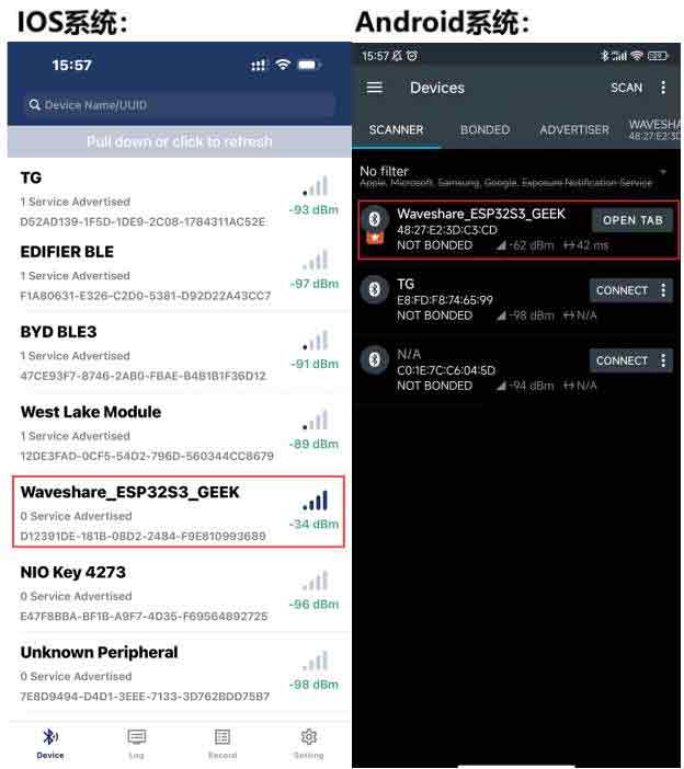
- Use the mobile phone to open the Bluetooth debugging assistant to scan and connect the device.
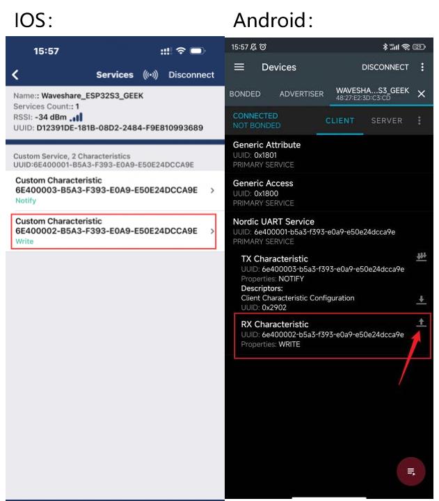
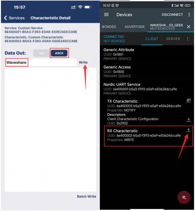
- Use the Bluetooth debugging assistant to send the message to ESP32-S3-GEEK, and the ESP32-S3-GEEK will display the message on the LCD after receiving it.
- Enter the receiving setting of the Bluetooth debugging assistant on the mobile phone:
- ESP32-S3-GEEK uses USB to UART tool to connect to the PC, open the serial debugging assistant, and send the UART message as a Bluetooth message to the mobile phone. Make sure to include the "Carriage Return" and "Line Feed" options when sending the message. The sent message will be displayed on the LCD. On the mobile device, observe if it receives the Bluetooth message.
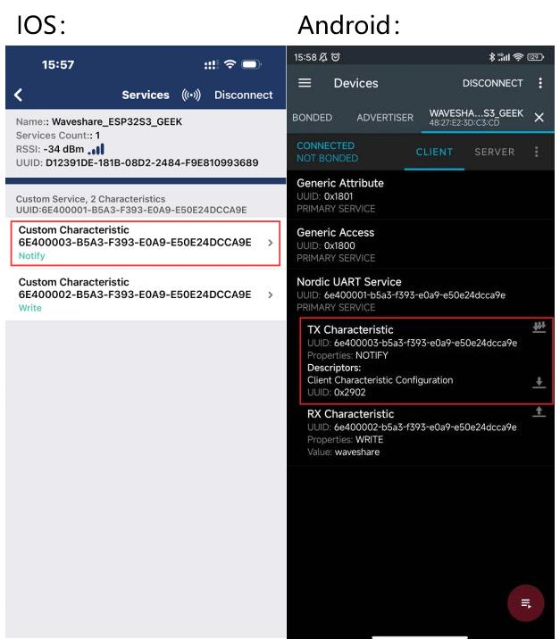
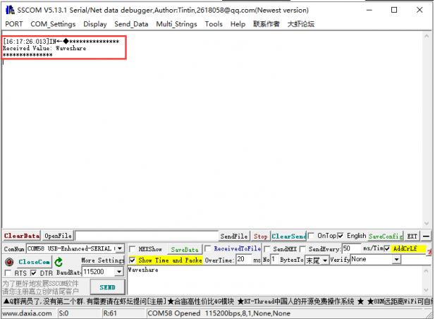
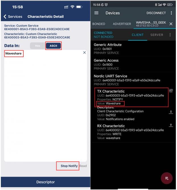
02-BLE_uart
This demo allows the ESP32-S3-GEEK to activate Bluetooth Low Energy (BLE). You can use a smartphone's Bluetooth debugging tool to connect to the ESP32-S3-GEEK, enabling BLE communication between the two devices. Sent and received messages will be displayed on the serial monitor, similar to BLE_LCD. However, this version doesn't activate the LCD, reducing power consumption significantly by using UART to display message content.
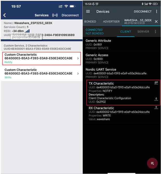
- In the code BLEDevice::init("Waveshare_ESP32S3_GEEK"), "Waveshare_ESP32S3_GEEK" is the Bluetooth device name.
- With a mobile Bluetooth debugging tool, scan and connect to devices.
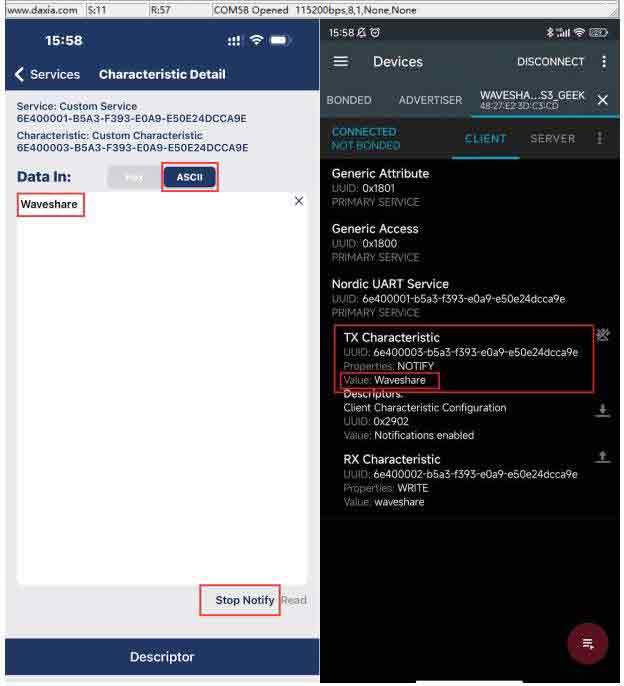
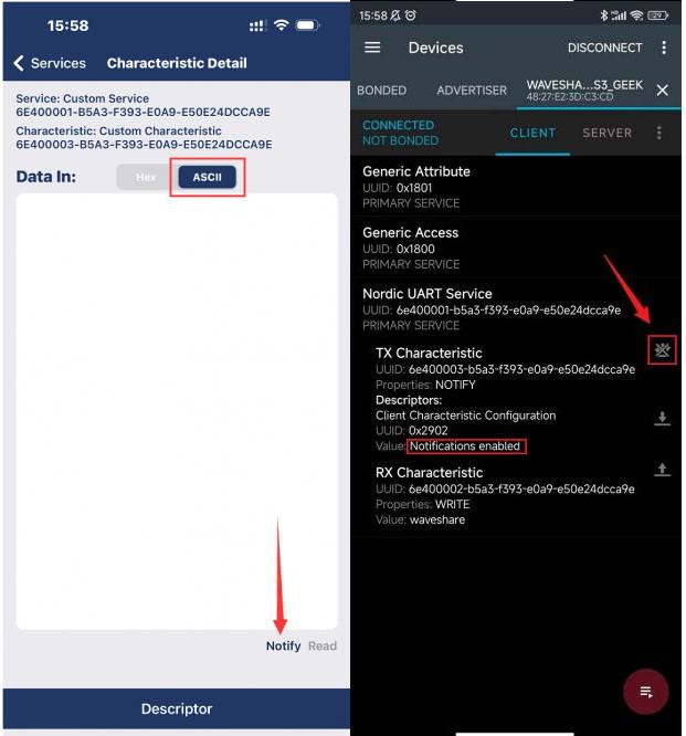
- Using the tool, send Bluetooth messages from the mobile device to the ESP32-S3-GEEK. The received messages will be displayed on the serial debugging assistant of the ESP32-S3-GEEK.
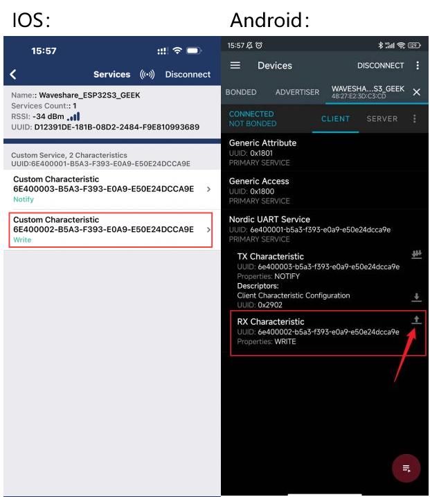
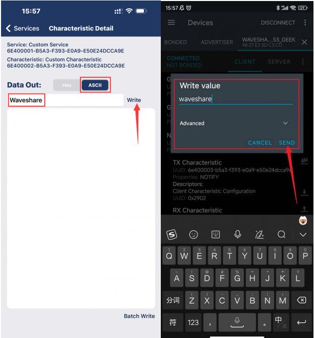
- Enter the receiving setting of the Bluetooth debugging tool on the phone.
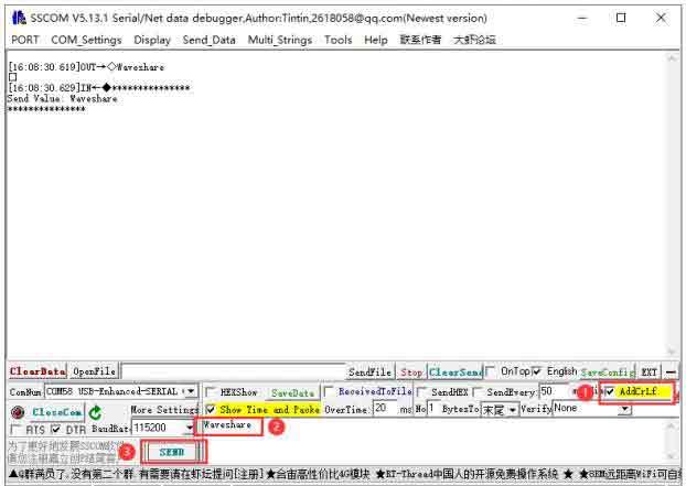
- ESP32-S3-GEEK, connected to the PC via CH343 USB UART Board (mini), opens a serial debugging tool. Messages sent via serial are converted into Bluetooth messages to the phone. Ensure to append a carriage return/Enter as an ending delimiter while sending. The message content will be displayed on the LCD. Check on the mobile device to observe if it receives the Bluetooth message.
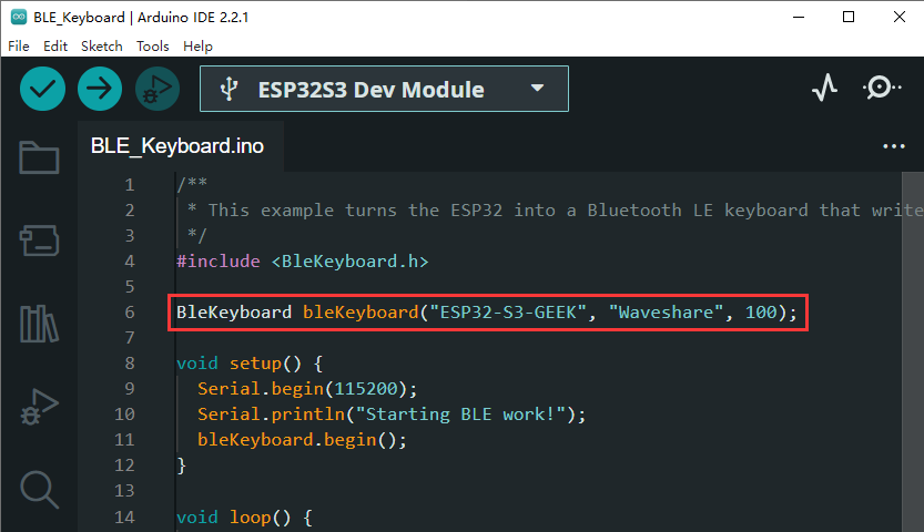
03-BLE_Keyboard
This code enables the ESP32-S3-GEEK to function as a Bluetooth keyboard. Once connected via the PC's Bluetooth, you can perform a series of single-key or combination-key operations. The ESP32-S3-GEEK will simulate these key presses and transmit corresponding keyboard inputs to the connected device.
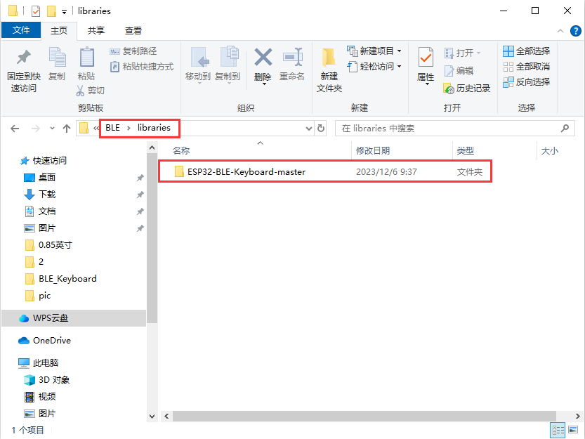
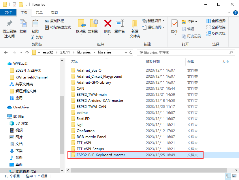
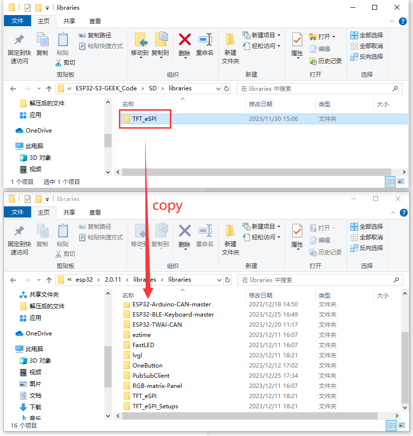
- Before using BLE_Keyboard, you need to add the ESP32-BLE-Keyboard Arduino library folder from the libraries directory into the libraries folder within the installation directory of Arduino IDE.

- If the Arduino library of the ESP32-BLE-Keyboard has been installed, pay attention to modifying the BleKeyboard.c file as shown below:
BLESecurity *pSecurity = new BLESecurity();
pSecurity->setAuthenticationMode(ESP_LE_AUTH_REQ_SC_MITM_BOND);

Modify it as:
BLESecurity *pSecurity = new BLESecurity();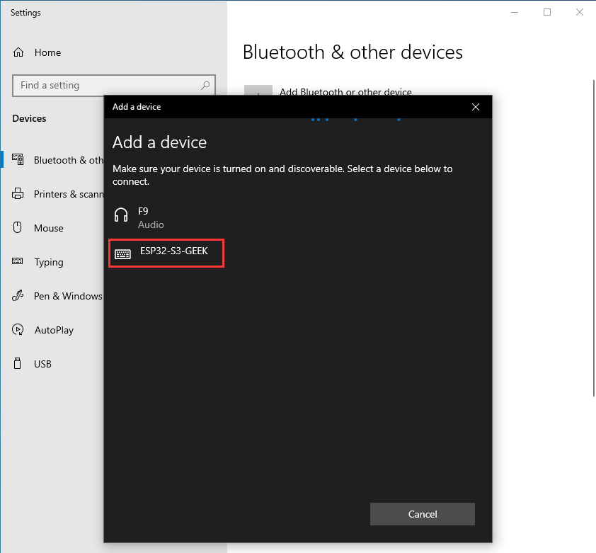
pSecurity->setAuthenticationMode(ESP_LE_AUTH_BOND);- ESP32-S3-GEEK is the name of the Bluetooth keyboard:
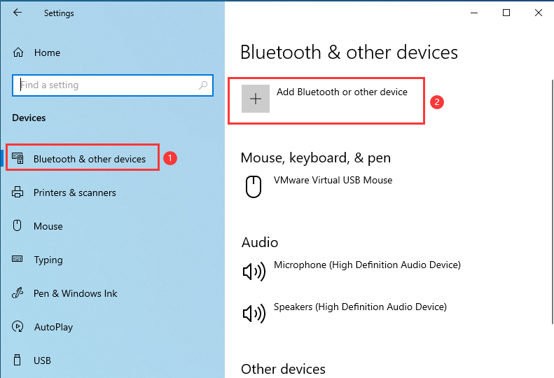
- Use PC to enter Bluetooth to scan and connect the device:

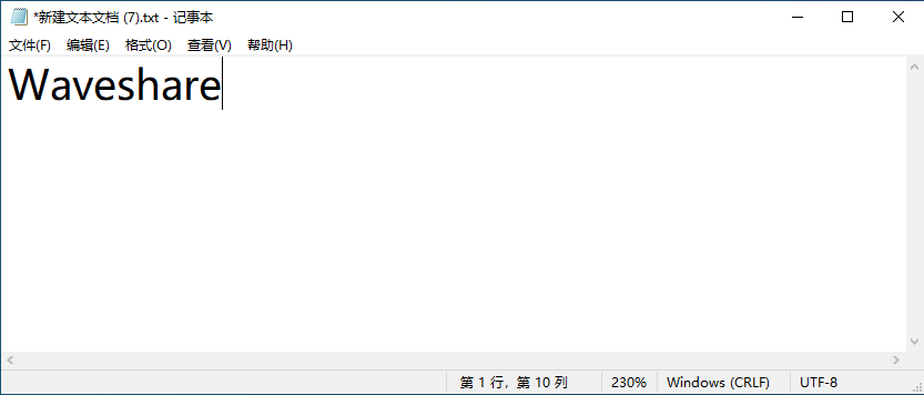
- After a successful connection, a series of keyboard actions are performed every 5 seconds (output "Waveshare", Ctrl+Alt+Delete).
- Modify the code with your unlock code to enable automatic locking and unlocking operations.

- You can view the value of each key in the BleKeyboard.h file of the libraries file folder.
const uint8_t KEY_LEFT_CTRL = 0x80;
const uint8_t KEY_LEFT_SHIFT = 0x81;
const uint8_t KEY_LEFT_ALT = 0x82;
const uint8_t KEY_LEFT_GUI = 0x83;
const uint8_t KEY_RIGHT_CTRL = 0x84;
const uint8_t KEY_RIGHT_SHIFT = 0x85;
const uint8_t KEY_RIGHT_ALT = 0x86;
const uint8_t KEY_RIGHT_GUI = 0x87;

const uint8_t KEY_UP_ARROW = 0xDA;
const uint8_t KEY_DOWN_ARROW = 0xD9;
const uint8_t KEY_LEFT_ARROW = 0xD8;
const uint8_t KEY_RIGHT_ARROW = 0xD7;
const uint8_t KEY_BACKSPACE = 0xB2;
const uint8_t KEY_TAB = 0xB3;
const uint8_t KEY_RETURN = 0xB0;
const uint8_t KEY_ESC = 0xB1;
const uint8_t KEY_INSERT = 0xD1;
const uint8_t KEY_PRTSC = 0xCE;
const uint8_t KEY_DELETE = 0xD4;
const uint8_t KEY_PAGE_UP = 0xD3;
const uint8_t KEY_PAGE_DOWN = 0xD6;
const uint8_t KEY_HOME = 0xD2;
const uint8_t KEY_END = 0xD5;
const uint8_t KEY_CAPS_LOCK = 0xC1;
const uint8_t KEY_F1 = 0xC2;
const uint8_t KEY_F2 = 0xC3;
const uint8_t KEY_F3 = 0xC4;
const uint8_t KEY_F4 = 0xC5;
const uint8_t KEY_F5 = 0xC6;
const uint8_t KEY_F6 = 0xC7;
const uint8_t KEY_F7 = 0xC8;
const uint8_t KEY_F8 = 0xC9;
const uint8_t KEY_F9 = 0xCA;
const uint8_t KEY_F10 = 0xCB;
const uint8_t KEY_F11 = 0xCC;
const uint8_t KEY_F12 = 0xCD;
const uint8_t KEY_F13 = 0xF0;
const uint8_t KEY_F14 = 0xF1;
const uint8_t KEY_F15 = 0xF2;
const uint8_t KEY_F16 = 0xF3;
const uint8_t KEY_F17 = 0xF4;
const uint8_t KEY_F18 = 0xF5;
const uint8_t KEY_F19 = 0xF6;
const uint8_t KEY_F20 = 0xF7;
const uint8_t KEY_F21 = 0xF8;
const uint8_t KEY_F22 = 0xF9;
const uint8_t KEY_F23 = 0xFA;
const uint8_t KEY_F24 = 0xFB;

const uint8_t KEY_NUM_0 = 0xEA;
const uint8_t KEY_NUM_1 = 0xE1;
const uint8_t KEY_NUM_2 = 0xE2;
const uint8_t KEY_NUM_3 = 0xE3;
const uint8_t KEY_NUM_4 = 0xE4;
const uint8_t KEY_NUM_5 = 0xE5;
const uint8_t KEY_NUM_6 = 0xE6;
const uint8_t KEY_NUM_7 = 0xE7;
const uint8_t KEY_NUM_8 = 0xE8;
const uint8_t KEY_NUM_9 = 0xE9;
const uint8_t KEY_NUM_SLASH = 0xDC;
const uint8_t KEY_NUM_ASTERISK = 0xDD;
const uint8_t KEY_NUM_MINUS = 0xDE;
const uint8_t KEY_NUM_PLUS = 0xDF;
const uint8_t KEY_NUM_ENTER = 0xE0;
const uint8_t KEY_NUM_PERIOD = 0xEB;

typedef uint8_t MediaKeyReport[2];

const MediaKeyReport KEY_MEDIA_NEXT_TRACK = {1, 0};
const MediaKeyReport KEY_MEDIA_PREVIOUS_TRACK = {2, 0};
const MediaKeyReport KEY_MEDIA_STOP = {4, 0};
const MediaKeyReport KEY_MEDIA_PLAY_PAUSE = {8, 0};
const MediaKeyReport KEY_MEDIA_MUTE = {16, 0};
const MediaKeyReport KEY_MEDIA_VOLUME_UP = {32, 0};
const MediaKeyReport KEY_MEDIA_VOLUME_DOWN = {64, 0};
const MediaKeyReport KEY_MEDIA_WWW_HOME = {128, 0};
const MediaKeyReport KEY_MEDIA_LOCAL_MACHINE_BROWSER = {0, 1}; // Opens "My Computer" on Windows
const MediaKeyReport KEY_MEDIA_CALCULATOR = {0, 2};
const MediaKeyReport KEY_MEDIA_WWW_BOOKMARKS = {0, 4};
const MediaKeyReport KEY_MEDIA_WWW_SEARCH = {0, 8};
const MediaKeyReport KEY_MEDIA_WWW_STOP = {0, 16};
const MediaKeyReport KEY_MEDIA_WWW_BACK = {0, 32};
const MediaKeyReport KEY_MEDIA_CONSUMER_CONTROL_CONFIGURATION = {0, 64}; // Media Selection
const MediaKeyReport KEY_MEDIA_EMAIL_READER = {0, 128};
MQTT
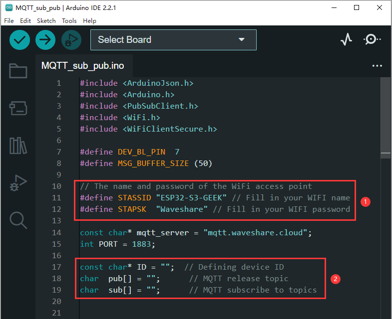
01-MQTT_sub_pub
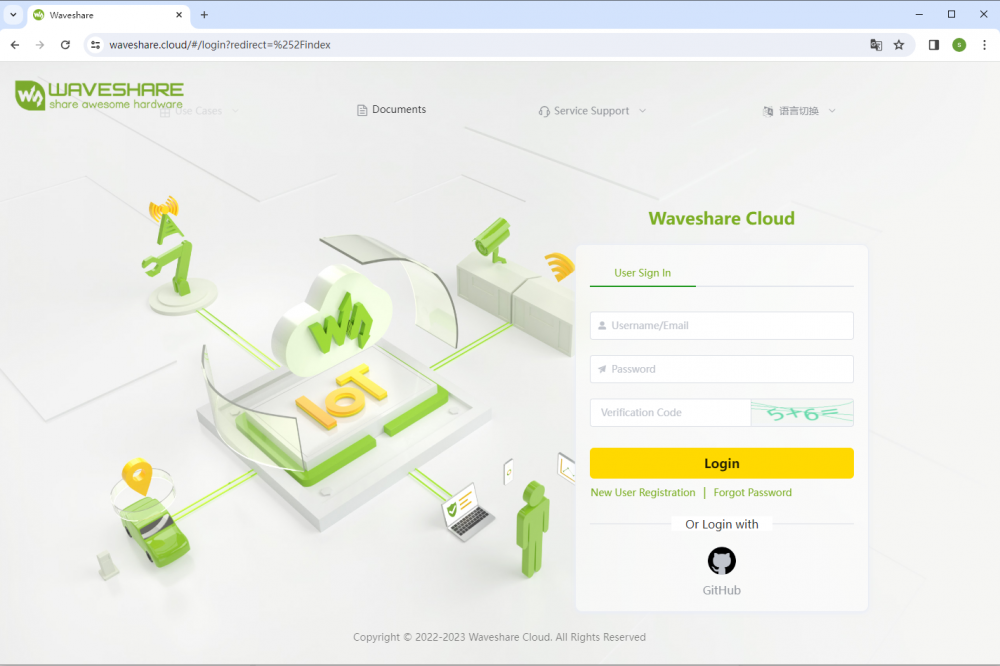
The demo can use ESP32-S3-GEEK to open the STA mode of WIFI, connect to the WIFI, and then use the Waveshare cloud platform to carry out MQTT communication, subscribe and publish topics, and realize the long-distance transmission of information.
- When you are the first time to register on the Waveshare cloud, you need to create a new device according to the tutorial.

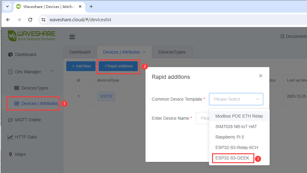
- After creating, you can set the corresponding configuration in the Arduino IDE according to ESP32SDK tutorial.
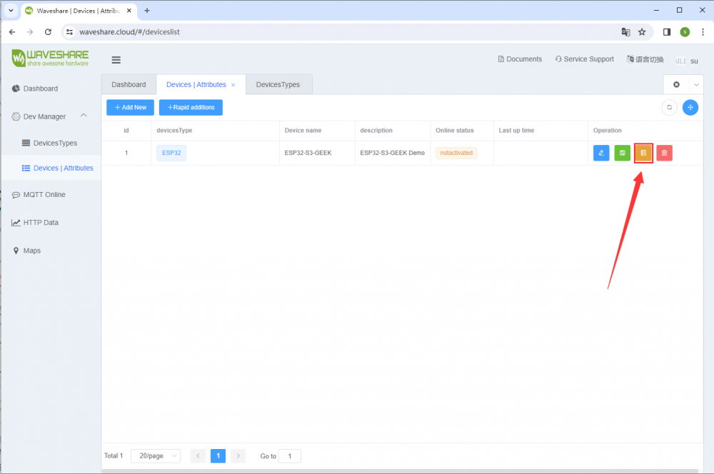
- After configuration, you can find the Client ID, Pub Topic, and Sub Topic of the newly created device on Waveshare's cloud platform under "View Address". You can assign these values in the code to facilitate ESP32-S3-GEEK's connection to your cloud platform device.
- Ensure that ESP32-S3-GEEK is set to STA mode and connected to the same Wi-Fi network as your device. The Wi-Fi network ESP32-S3-GEEK connects to needs to support the 2.4GHz frequency band. In case it doesn't, you can use a PC to create a hotspot with the network frequency set to "Any available frequency". Remember to modify the ssid and password with the name and password of the Wi-Fi network you want to connect to.
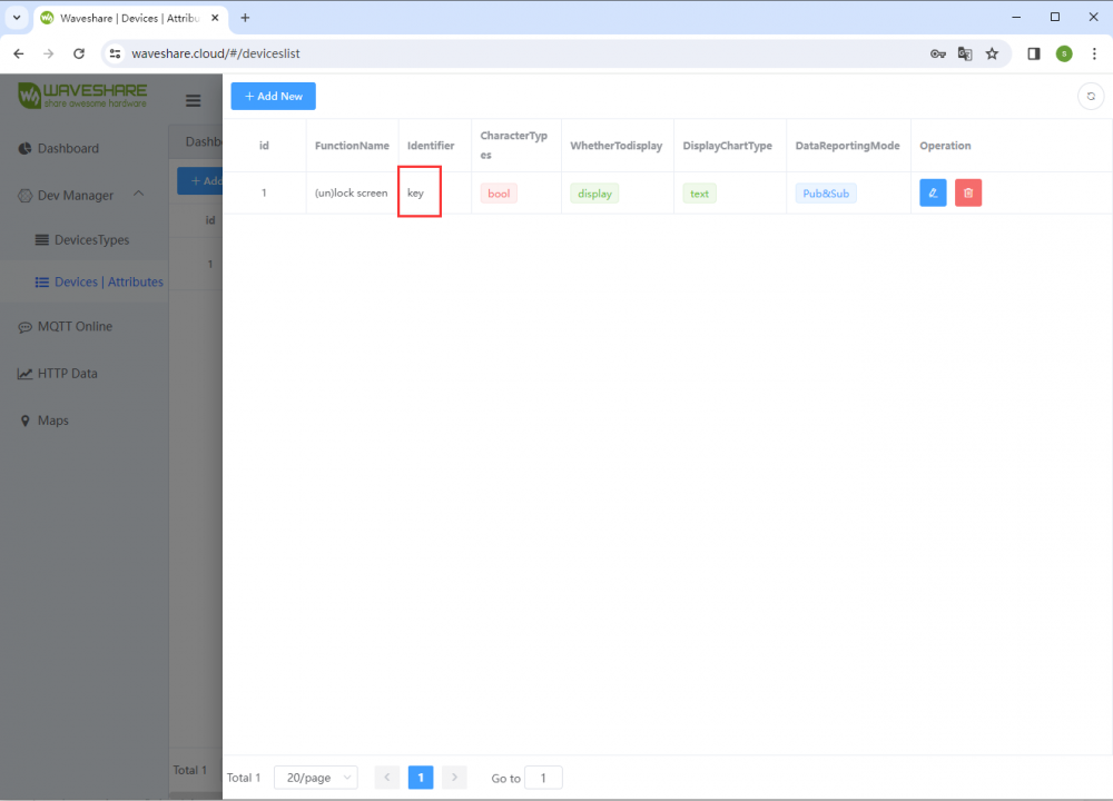
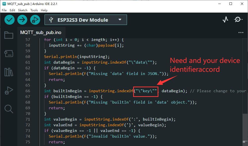
- In the callback function, you can modify the identification tag to our device attribute identifier created on the cloud platform.
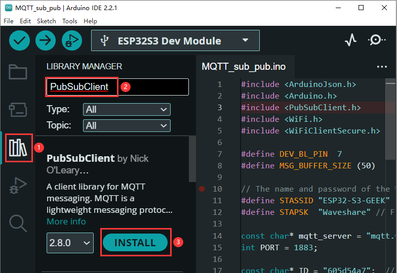
- Install PubSubClient library, LIBRARY MANAGER -> Search PubSubClient -> INSTALL.
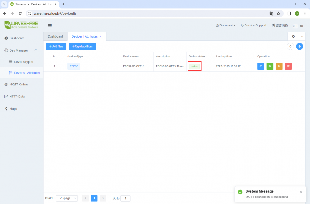
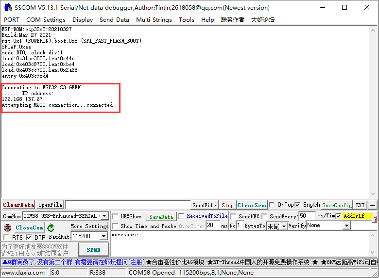
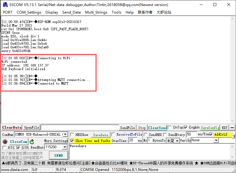
- Program the code, and after connecting to the WIFI, you can observe whether the Waveshare cloud platform enters "online" status. If not, you can try to refresh the webpage, use CH343 USB UART Board (mini) to connect to the PC through the serial debugging assistant and check the connection between the WIFI and MQRR. The LCD screen will display the connection between the WIFI and MQTT.
- After connecting ESP32-S3-GEEK to Waveshare Cloud, you can directly send the MQTT message through the Dashboard.
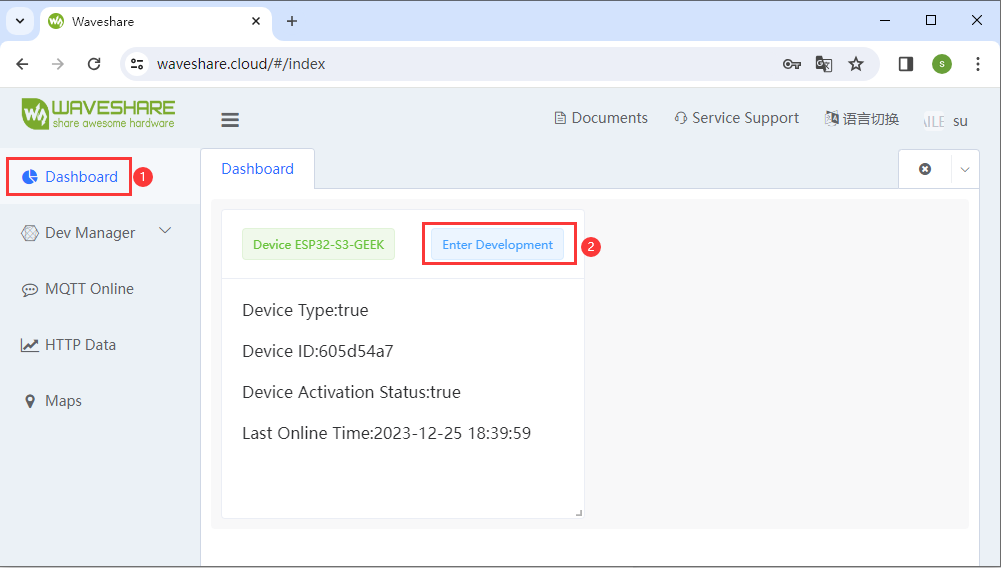
- We can observe different feedback regarding changes in device attribute values (e.g., "key") on both the LCD and the serial debugging assistant. Moreover, within Waveshare's cloud platform, under the device's received values, we can view the data transmitted from ESP32-S3-GEEK to the Waveshare cloud device (the received value corresponds to its Client ID). Subsequently, one can send the return value or status of the 'key' back to the Waveshare cloud. This completes the implementation of MQTT for both data uplink and downlink, as well as topic subscription and publication.
02-MQTT_BLE_Keyboard
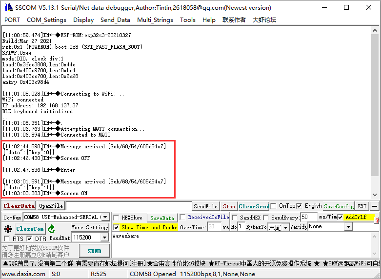
This demo enables ESP32-S3-GEEK to enter the STA mode of the WIFI and Bluetooth. After connecting the WIFI and Bluetooth, on the Waveshare Cloud platform, it's possible to remotely lock the screen via Bluetooth and unlock it by entering a password. Additionally, there are more combinations of keys awaiting your development.
- When you are the first time to register on the Waveshare Cloud, you need to create a new device according to the tutorial.

- After creating, you can set the corresponding configuration in the Arduino IDE according to ESP32SDK tutorial.
- After the configuration is complete, according to the "View Address" of the newly created device on Waveshare Cloud, you can see the "Client ID, Pub Topic, and Sub Topic" of the device, and you can write them into the demo for assigning values, which can be used for ESP32-S3-GEEK to connect to your cloud platform device.
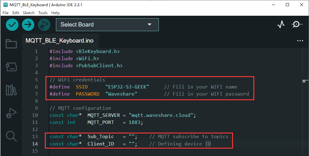
- ESP32-S3-GEEK connects in STA mode to the same Wi-Fi network (which needs to operate on the 2.4GHz frequency band). If the network doesn't support 2.4GHz, you can create a hotspot on your PC with the network frequency set to "Any available frequency." Remember to modify the ssid and password with the appropriate Wi-Fi name and password.
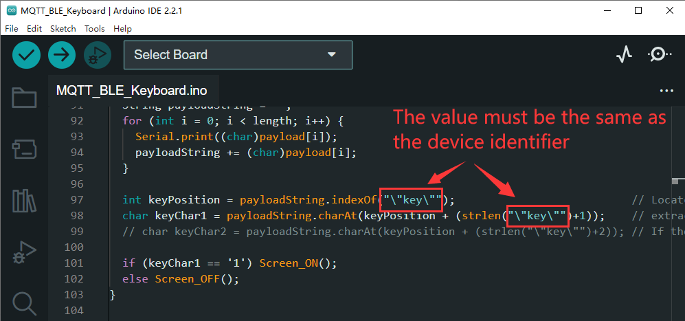
- In the callback function, you can customize the identification tag to match the device attribute identifier you've created on our cloud platform.

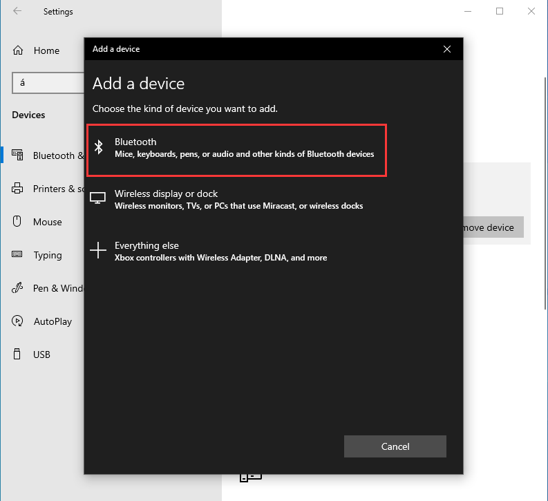
- Programming the code, after connecting to the WIFI, you can open PC Bluetooth to connect the ESP32-S3-GEEK.


- Observe whether the device is on the Waveshare cloud platform in the online state, if not, you can try to refresh the web page with the use of CH343_USB_UART_Boardto connect to the PC through the serial debugging assistant to view the WIFI and MQTT connection, and in the LCD will also display the WIFI and MQTT connections.

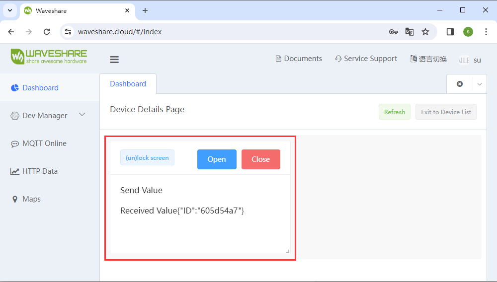
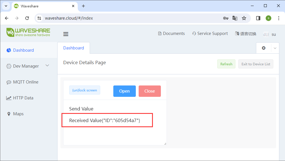
- After the ESP32-S30GEEK connects to the Waveshare Cloud, you can log in to the Waveshare Cloud Dashboard on your phone remotely lock the PC screen, and input a password for screen unlocking.
- We can observe the changes in device attribute values (e.g., "key") reflected in both the LCD and serial debugging assistant. Additionally, we can further customize the callback function to modify keys into combinations like Ctrl+C, and Ctrl+V, allowing for a personalized DIY remote-controlled Bluetooth keyboard.
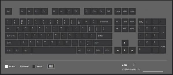
- Or you can enter keyboard tester website to test the keys remotely pressed by the ESP32-S3-GEEK Bluetooth.
SD
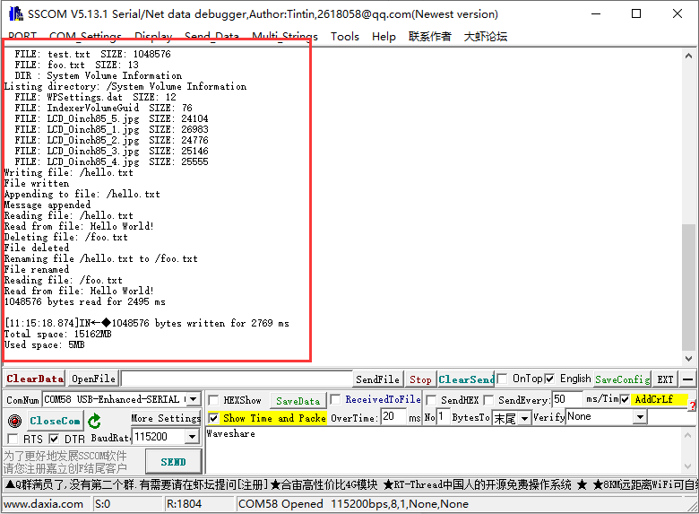
01-SD_Test
This demo allows the use of ESP32-S3-GEEK's SD card slot. Insert an SD card into the slot and open the serial debugging assistant. You'll be able to observe ESP32-S3-GEEK performing operations such as creating, deleting, modifying, and checking files on the SD card.
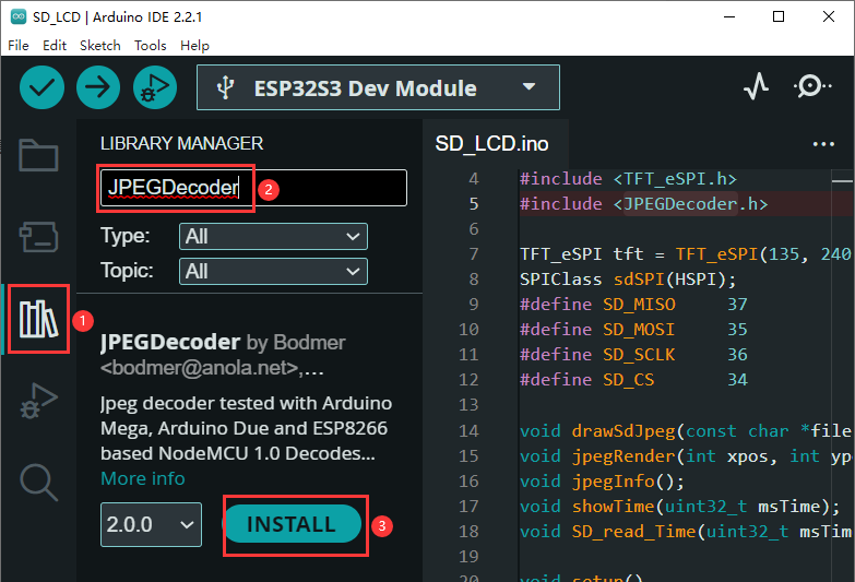
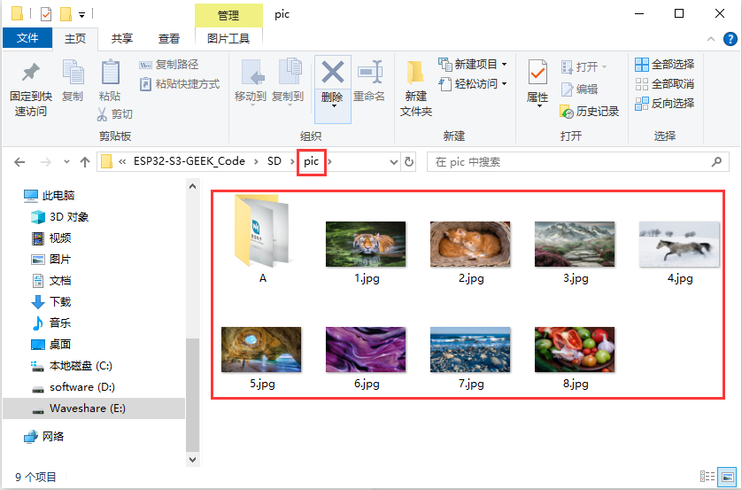
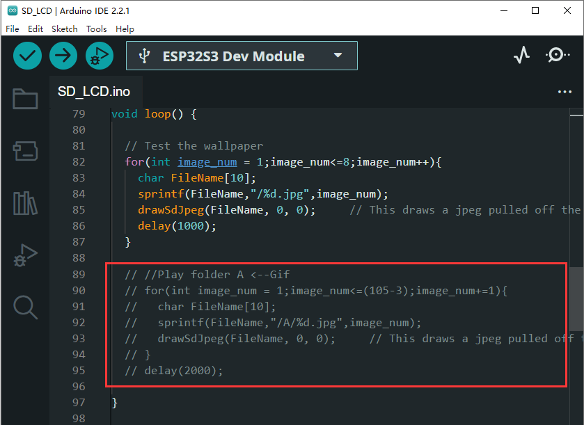
02-SD_LCD
With this demo, the pictures of the SD card in the SD card slot of the ESP32-S3-GEEK can be read. Store the pictures on the SD card, and insert it into the card slot. The ESP32-S3-GEEK can read and display the pictures of the SD card on the LCD, or it can flash the pictures as a gif.
- Copy the TFT_eSPI file folder of the libraries to the library installation directory of Arduino.

- Install JPEGDecoder library, LIBRARY MANAGER -> search for JPEGDecoder -> INSTALL.
- You can store the pictures of "pic" on the SD card, or you can store your pictures, and modify the picture size to 240×135, and the display effect is the best.
- This part of the comment is removed to play the Waveshare startup animation.

LCD
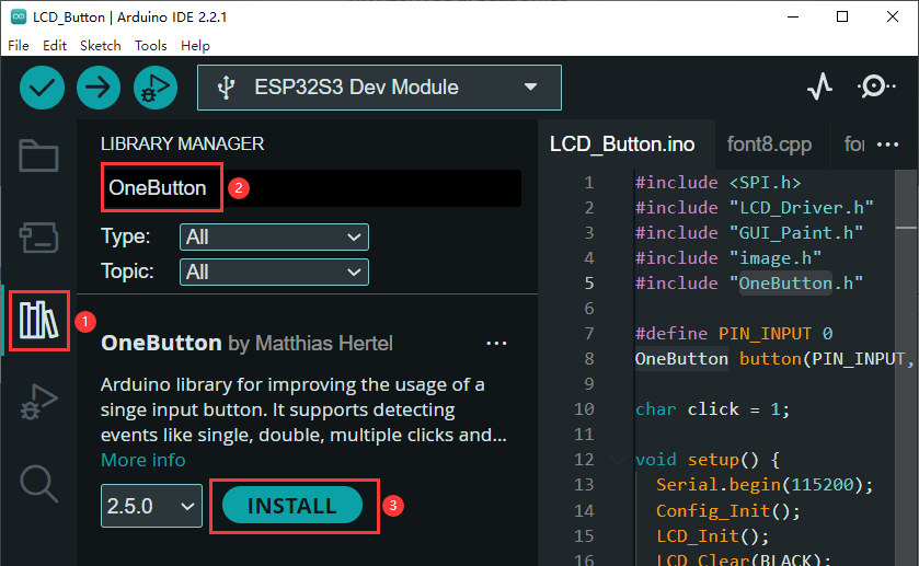
01-LCD_Button
This demo can use the boot button of ESP32-S3-GEEK to realize a short press to light up the LCD and switch to the next picture, and a long press to turn off the LCD.
- Install OneButton library, LIBRARY MANAGER -> search for OneButton -> INSTALL.
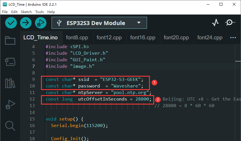
02-LCD_Time
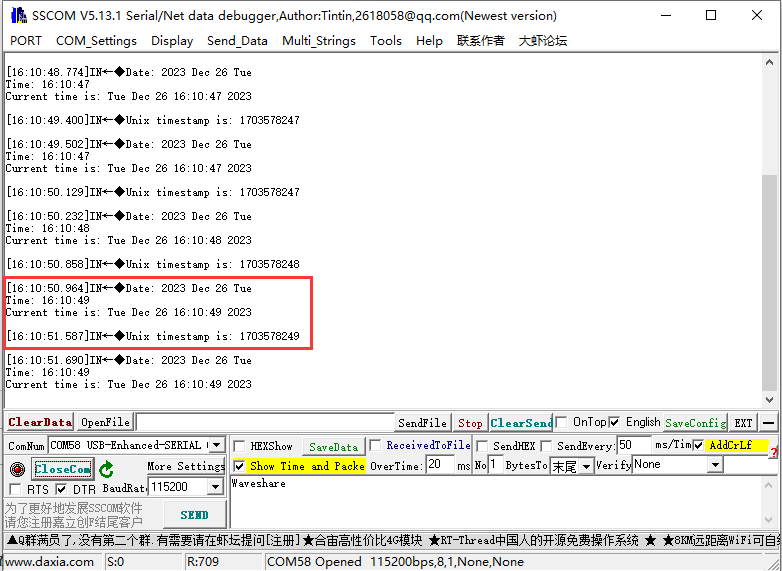
This demo allows ESP32-S3-GEEK to connect to WiFi and obtain the current time. It then displays the date and time on both the LCD and the serial debugging assistant.
- Modify the ssid and password to the name and password of the Wi-Fi network you want. (The WIFI of the ESP32-S3-GEEK connected requires the Wi-Fi network of the 2.4GHz frequency band. If there's no 2.4GHz band available, create a hotspot on your PC with the network frequency set to "Any available frequency. For instance, if you need the time zone for Beijing (GMT+8), set utcOffsetInSeconds to 86060=28800.
- After programming the code, you can see the LCD the real-time and date. ESP32-S3-GEEK uses USB to UART to connect to the PC, open the serial port debugging assistant, and you can see the time and date obtained printed on the serial port debugging assistant.
Button
01-OneButton
With this demo, the boot key on the ESP32-S3-GEEK is modified as a multi-functional key, capable of executing different operations based on single-click, double-click, or long-press actions.
- Install OneButton library, LIBRARY MANAGER -> search for OneButton-> INSTALL.
- You can modify different processing functions by the following code. For more details, you can click here to view.
Once a click is detected, it triggers: void Click(void *oneButton)
Once a double click is detected, it triggers: void DoubleClick(void *oneButton)
Once long press is detected, it triggers: void LongPressStart(void *oneButton)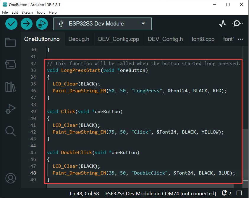
UART
01-UART0
This demo uses ESP32-S3-GEEK to open UART0 and open the serial port assistant for UART communication.
IIC
01-IIC_BME68X_Sensor
With this demo, the IIC hardware interface of the ESP32-S3-GEEK drives the IIC module.
- The demo uses the BME680 environmental sensor. You can find detailed instructions and implementation effects in the tutorial.
ADC
01-ADC_Read
This example allows the use of ESP32-S3-GEEK's GPIO interface for ADC sampling, enabling the reading of voltages within the 3.3V range. When using it, ensure a common ground and avoid exceeding the measurement range.
Wireless_USB_flash_drive
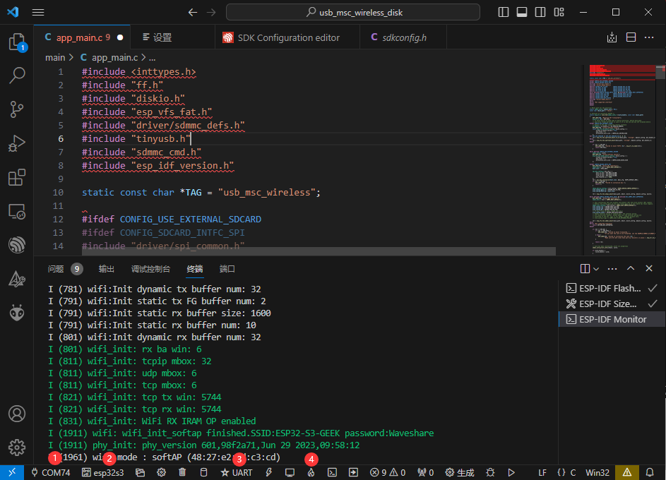
01-usb_msc_wireless_disk
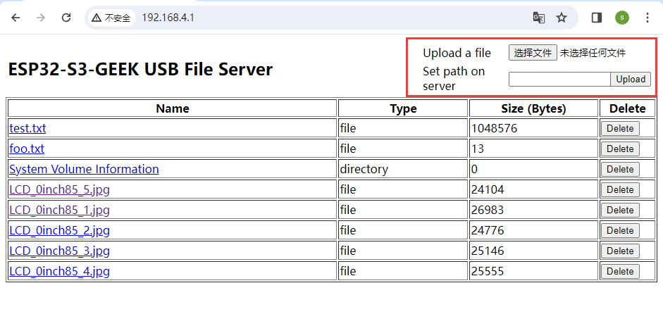
This demo allows ESP32-S3-GEEK to function as a USB flash driver with wireless access. When combined with an SD card, it transforms into a high-capacity wireless storage unit. Additionally, it enables connecting to ESP32-S3-GEEK's hotspot to engage in HTTP file server operations for both uploads and downloads, significantly enhancing user convenience.
- Before programming the demo, please insert the SD card into the SD card slot, and check whether the programming chip is esp32s3, and the COM port is correct or not. The programming method selects UARI.
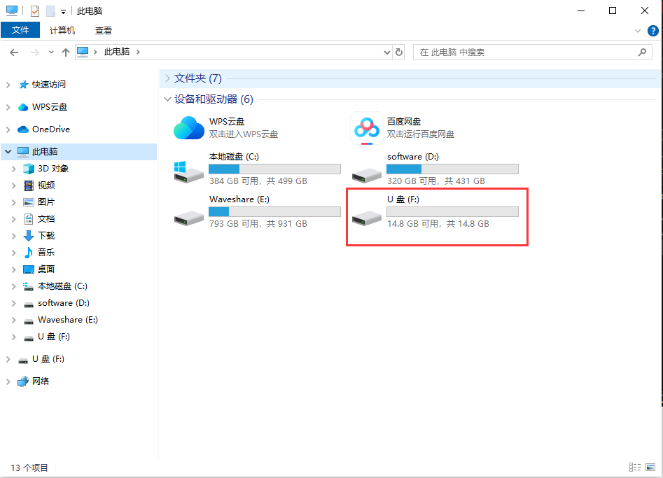
- After programming, unplug and plug the ESP32-S3-GEEK again, and you can see a new USB flash driver.
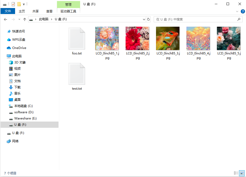
- You can open the USB drive to browse through the files on the SD card and perform various operations such as adding, deleting, modifying, and checking files.
- Enter the PC's WIFI setting, connect to the ESP32-S3-GEEK's AP, and input the password of "Waveshare".
- After connecting successfully, open the browser, and log in to IP: 192.168.4.1.
- After login successfully, you can upload and download files wirelessly.
TAG:
Jetson
Raspberry Pi Game
Circular LCD Screen
USB Monitor
Arducam
BPI
TTL To CAN Mini
Raspberry Pi 5 Official Case
Information
ADXL354C Development Board
Aluminum Heatsink
Luckfox Pico LCD
JETSON NANO MINI
Arduino Thermal imaging camera
Raspberry Pi AF Camera
Raspberry Pi 5 Case
ESP32 Thermal imaging camera
Pi5 Active Cooler
1.3inch LCD
LuckFox Pico Camera
Price:
$12.89
Part Number:
ESP32-S3-GEEK
Brand:
Spotpear
SKU:
0101610
TAG:
Raspberry Pi 11.9inch LCD
Arduino E-ink
Raspberry Pi 5
Arduino Nano ESP32-S3R8
Milk-V Duo S 512MB SG2000 RISC-V
SpotPear
Raspberry Pi 5 Official Case
1.91Inch AMOLED
Raspberry Pi Zero USB HUB
VGA to RGB
Raspberry Pi 5 PoE Moudle
RP2040 0.85inch LCD
Arduino UNO R4 case
Orange Pi
Raspberry Pi Pico
ESP32
Raspberry Pi
Orange Pi Zero 2W
ESP32 S3 I2C
Arduino UNO R4