- sales/support
Google Chat: zj734465502@gmail.com
- sales
+86-0755-88291180
- sales01
sales01@spotpear.com
- sales02
dragon_manager@163.com
- support
services01@spotpear.com
- CEO-Complaints
manager01@spotpear.com
- sales/support
WhatsApp:13246739196
- HOME
- >
- ARTICLES
- >
- Common Moudle
- >
- UART Module
USB-CAN-FD User Guide
Software
Introduction
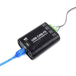
The USB-CAN-FD is an industrial-grade high-performance USB to CAN FD adapter, CAN/CAN-FD bus communication interface card, and CAN/CAN-FD protocol data analyzer. Onboard dual independent CAN FD interfaces with electrical isolation and multiple protection circuits. Supports Windows XP/7/8/10/11 system, comes with drivers, CAN FD Tools related software, secondary development examples, and tutorials.
It can be connected to the PC or industrial control host via a USB port to realize transceiver control, data analysis, collection and monitoring of CAN/CAN FD bus network. It is compact in size and easy to use, which can be used for learning and debugging of CAN/CAN FD bus, as well as for secondary development and integration into various industrial, power communication, and intelligent control applications that require CAN/CAN FD bus communication.
Specification
| Model | USB-CAN-B | USB-CAN-FD | |
|---|---|---|---|
| Product Type | Industrial Grade | USB to CAN Interface Converter / CAN-bus Communication Card/ CAN Protocol Data Analyer | Industrial Grade: USB to CAN FD interface converter, CAN/CAN FD serial bus communication interface card, CAN/CAN FD protocol data analyzer |
| USB Port | Working Voltage | 5V (Directly powered via USB port, no additional power supply required.) | |
| Interface Form | USB-B Port | ||
| CAN/CAN FD Interface | CAN/CAN FD Channels | Dual channels: CAN1 and CAN2 (Independent of each other, do not affect each other, full isolation, isolation voltage 3000V DC) | |
| Interface Form | Screw Terminal (OPEN6 5.08mm pitch) | ||
| Matching Resistor | Each CAN/CAN FD channel has two built-in 120Ω terminal resistors, which can be enabled by switch | ||
| Baudrate | 10Kbps~1Mbps (Configurable via software) | 100Kbps~5Mbps (Configurable via software) | |
| Protocol Support | CAN2.0A and 2.0B, CANOpen, SAE J1939, DeviceNet, iCAN, ISO 15765 protocol | CAN2.0A and 2.0B, ISO 11898-1 CAN FD Protocol V.1.0 | |
| Transfer Speed | The receiving and sending speed of each CAN/CAN FD channel can reach 8500 frames/s | The receiving and sending speed of each CAN/CAN FD channel can reach 20000 frames/s and 5000 frames/s | |
| Transmit Buffer | 2000 frames receiving buffer and 1000 frames sending buffer per channel (automatically retransmit when the transmission fails) | 1500 frames receiving buffer and 64 frames sending buffer per channel (automatically retransmit when the transmission fails) | |
| Indicator | PWR | Power Indicator | |
| SYS | System status indicator, normally off; keeps on when there is a bus error | ||
| CAN1 | CAN1 channel indicator (blinking when sending and receiving data) | ||
| CAN2 | CAN2 channel indicator (blinking when sending and receiving data) | ||
| System Support | Windows | Windows XP/7/8/10/11 (32 bits and 64 bits) | |
| Linux | Linux systems such as Raspberry Pi OS, Ubuntu (Jetson Nano), VMware virtual machines, etc. | Does Not support the Linux system now, and the related drivers are under development. | |
| Operating Temperature | -40~85℃ | ||
| Case Material | Aluminum alloy case + 3D flame-retardant insulating sheets on both sides (This design can provide better protection against metal tip discharge, also improves product safety, and extends service life) | ||
| Dimensions | 104 × 70 × 25 mm | ||
Windows PC User Guide
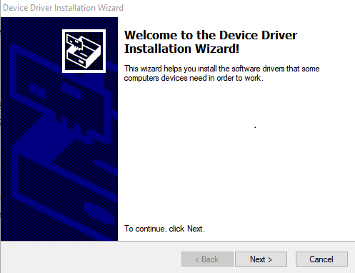
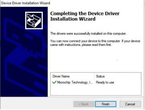
Use the USB cable to properly connect the USB-CAN-B Smart Interface Module to the PC. Once the hardware is detected, Windows will automatically run the installation wizard called "Discover New Hardware". Download Windows Driver.
- Click "Next" to continue;
USB-CAN-B Tool Software
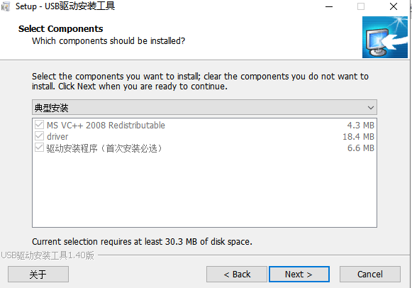
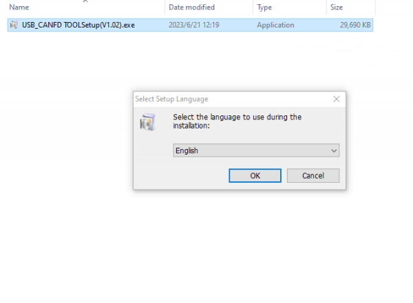
Download & Install
- Choose your language according to your personal habits, here is an example of English:
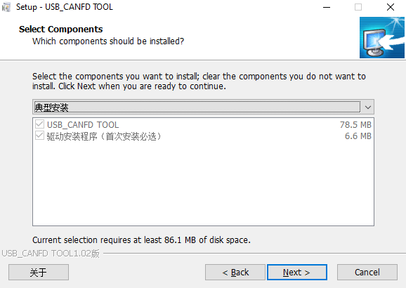
- Select the default option, click "Next".
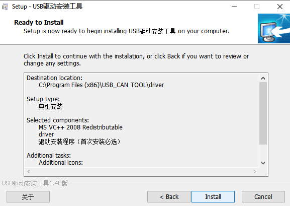
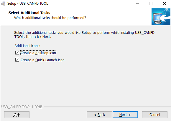
- It is recommended to check the box to create a desktop shortcut and continue to "Next".
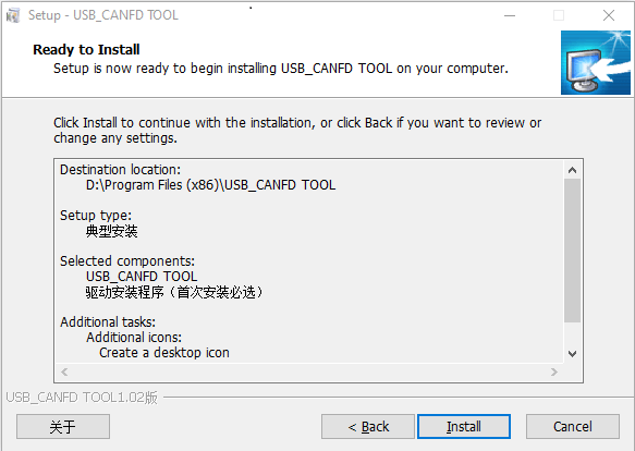
- Directly click "Install".
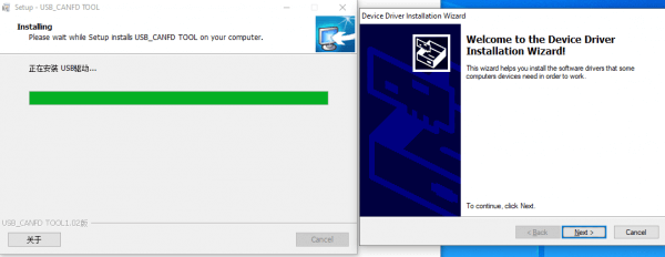
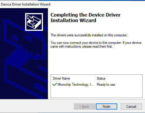
- After installation, continue to click "Next".
- After completing the installation, CANFDToolPro will appear on the desktop and in the applications.
User Guide
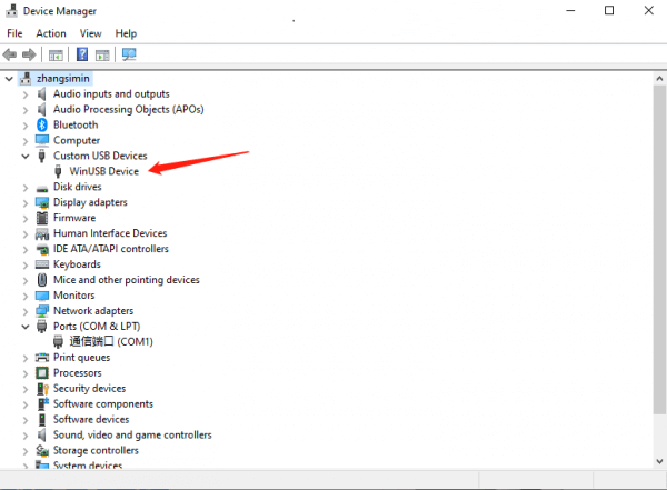
Connect the USB port of the device to the USB port of the PC via the USB cable.
Run "USB-CAN-FD_TOOL.exe", the following is the description of common functions.
1. Device Management
The software "Device Management" -> "Device Operation" can open the device management interface. Here you can open the device, start and stop the channel, set parameters, and other related operations.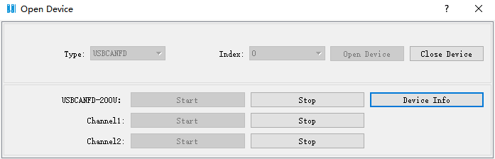
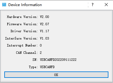
- Click "Device Information" to view the current device hardware version information.
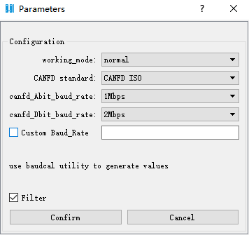
- When starting the channel, the parameter setting interface is as follows, you can select the working mode, CANFD standard, arbitration baud rate, data baud rate, and so on.
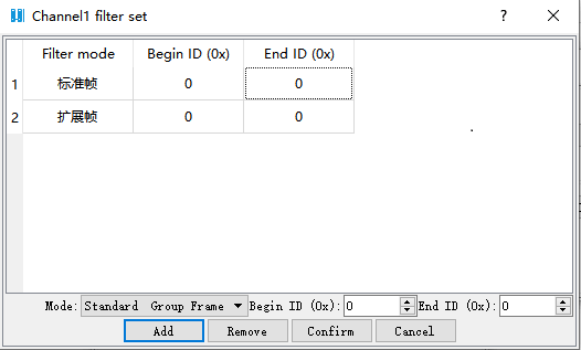
- The filter settings are shown below: Note that up to 64 filter groups can be set for standard frames and up to 32 filter groups can be set for extended frames.
Display Function
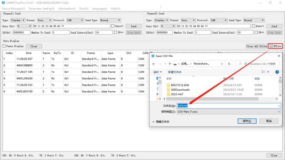
2.1 Save in Real Time
- The default save format is csv, if you want to save as txt format, then directly enter the .txt suffix.
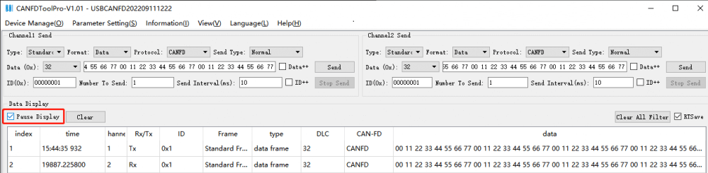
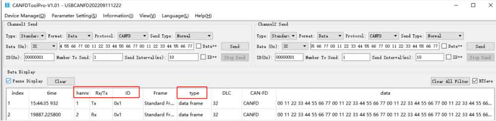
Pause Display
- When receiving data, you can check "Pause display" for the convenience of viewing the data (at this time, the data is still being received, just not displayed in the current interface). Uncheck the box and the data will continue to be displayed.
Transmission Counts
- At the bottom of the software, the total number of receipts and transmissions as well as the real-time frame rate of receipts and transmissions for the 2 channels are counted. Press the "Reset Count" button to clear the count.

Display Buffer
- Display Buffer indicates the maximum number of frames that can be displayed in the current interface, the default value is 1000.
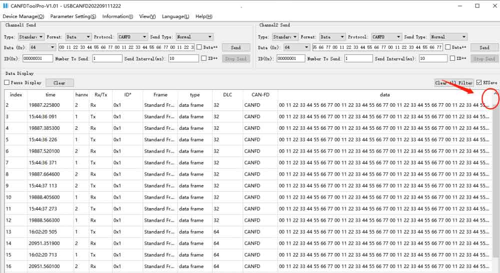
View the Data
- When the data is too long (e.g. 64 bytes), the interface can not display a complete frame of data, put the mouse to the following position, when it becomes a two-way symbol, double-click, and you can expand all the data content, drag the horizontal scroll bar below to view the data.
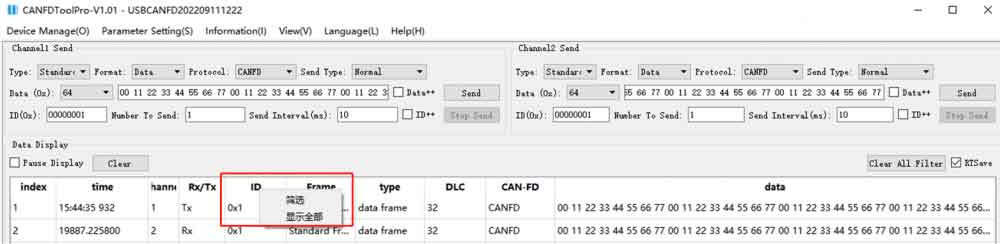
Filter Functions
- In the data display box, all the displayed items can be filtered. Filtering right-click to select the item to be filtered, and the filtering menu will pop up, click on "Filter" to pop up all the contents of the item that can be filtered; click on "Show All" to cancel the change of the filter conditions.

- The filter options will list all different values, and you can check one or more.
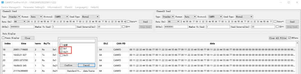
- Items that have been set up with filtering conditions will be prompted with a *, such as "ID" set up with filtering conditions, it will be displayed as "ID*".

- All the filter conditions are "and" relationship. For example, to view "Data frame with ID 0x55 for channel 1", you need to set the filter conditions as follows: Channel -> Select 1, Receive/Transmit -> Select Rx, ID -> Select 0x55, Type -> Select Data Frame. As shown in the figure below:
- If you want to clear all the set filters, click the "Delete all filters" button.