- sales/support
Google Chat: zj734465502@gmail.com
- sales
+86-0755-88291180
- sales01
sales01@spotpear.com
- sales02
dragon_manager@163.com
- support
services01@spotpear.com
- CEO-Complaints
manager01@spotpear.com
- sales/support
WhatsApp:13246739196
- HOME
- >
- ARTICLES
- >
- Common Moudle
- >
- Sensors
DTOF LIDAR STL27L User Guide
Introduction
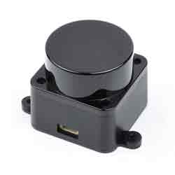
The STL-27L consists mainly of a laser ranging core, a wireless power transmission unit, a wireless communication unit, an angle measurement unit, a motor drive unit, and a mechanical case.
The laser ranging core of the STL-27L uses DTOF (Direct Time of Flight) technology, enabling it to perform 21,600 distance measurements per second. During each measurement, the lidar emits infrared laser beams that are reflected back to a single photon-receiving unit upon encountering a target object. By comparing the time when the laser is emitted and the time when it is received by the photon receiving unit, we can calculate the flight time of the laser, which, combined with the speed of light, allows us to determine the distance. After obtaining the distance data, it is fused with the angle measurements from the angle measurement unit to form point cloud data. This data is then wirelessly transmitted to an external interface.
The STL-27L has a compact and small structure, with the same shape and mounting holes as the LD19 lidar. It is suitable for applications that have strict requirements on space and appearance.
Features
- Maximum range is 25m, meeting most commercial service robot application scenarios.
- High-range accuracy at close range (0.03~2m), with average error within ±15mm.
- Extremely small size, easy to integrate design, and ensure the aesthetics of customer products.
- Strong resistance to environmental light interference, to meet the use of 60Klux environment.
- Support for glass wall detection.
- Laser safety in line with FDA Class 1 standards.
- Compact appearance.
- Stable performance with a lifetime of up to 10,000 hours.
Parameters
| RANGING DISTANCE | WHITE TARGET RANGING ACCURACY: 0.03 ~ 25m 80% BLACK TARGET RANGING ACCURACY: 0.03~10m 4% |
|---|---|
| RANGING ACCURACY | ±15mm@0.03m-2m, STD 5mm ±20mm@2m-8m, STD 15mm; ±30mm@>8m, STD 25mm |
| SCANNING FREQUENCY | 6Hz~13Hz (10Hz by default) |
| RANGING FREQUENCY | 21600 Hz |
| PITCH ANGLE ERROR | 0.5°~2° |
| YAW ANGLE ERROR | -1°~1° |
| AMBIENT LIGHT RESISTANCE | 60Lux (tested under sunlight condition) |
| WAVELENGTH | 895nm~905nm (Typ 905nm) |
| COMMUNICATION INTERFACE | UART @ 921600 |
| POWER SUPPLY | 4.5v~5.5v |
| OPERATING CURRENT | ≤290mA |
| OPERATING TEMPERATURE | -10℃~50℃ |
| PWM CONTROL FREQUENCY | 20kHz~50kHz |
| PWM DUTY CYCLE | 40%~100% |
| DIMENSIONS | 54.00*46.29*34.80 mm (L × W × H) |
| LIFETIME | 10000h |
Application Scenarios
- Education and research
- Robot obstacle avoidance
- Measurement and inspection
- Smart gesture control
- 2D gesture recognition
- Autonomous navigation
- Map reconstruction
- Navigation and positioning
How to Use
【Connection & Driver Installation】
Hardware wire connection and instructions:
1) The radar is connected to the adapter board as shown in the figure below, and the adapter board is connected to the host computer (here PC is used as an example):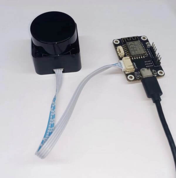
2) Connection as shown below: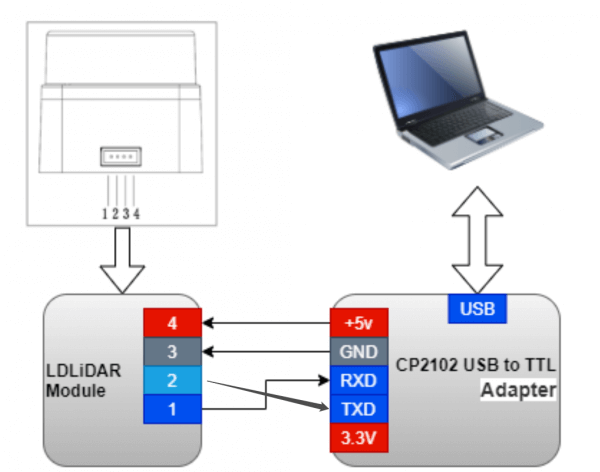
3) Download the corresponding radar test demo, if the CP2102 driver is not installed, then you need to install the driver, the driver and radar test program download link is as follows.
- LdsPointCloudViewer-x64
- LdsPointCloudViewer-x86
- CP210x_Universal_Windows_Driver.zip
- If the CP2102 driver is already installed, you can skip this step. After unpacking the CP210x_Universal_Windows_Driver package, execute the "exe" file in the driver installation package directory and select X86 (32-bit) or X64 (64-bit) depending on the Windows system version.
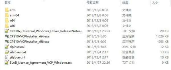
Double-click the "exe" file and install it with prompts.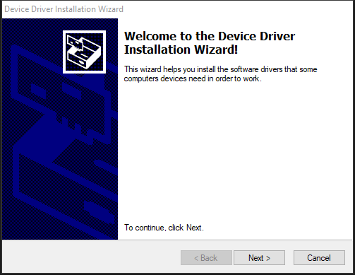
After the installation is completed, connect the USB adapter board in the development kit to the computer, you can right-click 【My Computer】, select 【Properties】, under the opened 【System】 interface, select 【Device Manager】 in the left menu to enter the device manager, expand 【Port】, you can see the serial port number corresponding to the recognized CP2102 USB adapter, that is, the driver is successfully installed, the figure below is COM4.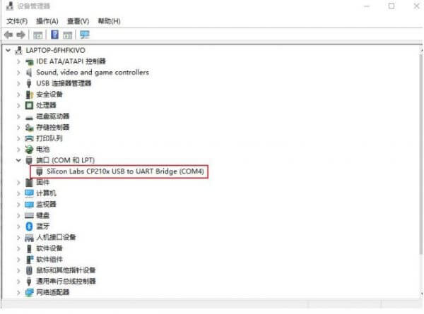
LdsPointCloudViewer Use
LdsPointCloudViewer, a point cloud visualization software for real-time scanning, allows developers to visually observe the scanning effect of the product. Before using the software, make sure that the driver of the USB adapter board has been successfully installed and the product is interconnected with the USB port of the Windows PC, then double-click LdsPointCloudViewer.exe, select the corresponding product model (e.g. LD14P) and port number, and click the LdsPointCloudViewer Refresh button, as shown in the figure below.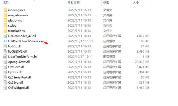
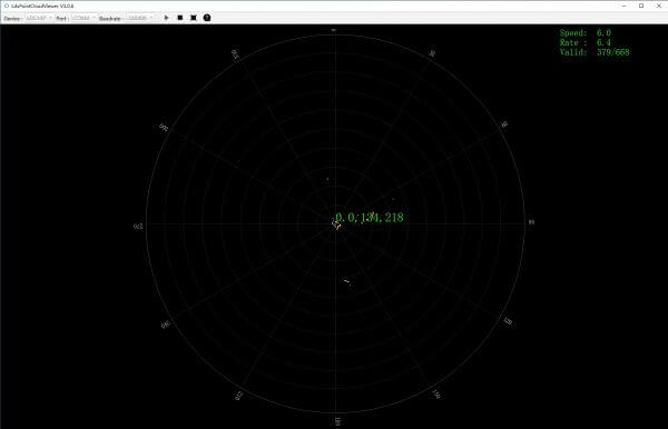
In the above figure, Speed is the LIDAR scanning frequency in Hz; Rate is the LIDAR packet resolution rate; Valid is the valid points of one lap measured by LIDAR.
Adapter Board Principle & Start-Stop Control
We use the ESP8266 as the main control chip in the adapter board. The board is equipped with CP2102. The TX (transmit) pin of the lidar is connected to the RX (receive) pin of CP2102. The RX pin of the ESP8266 is connected to the TX pin of CP2102. This means that you can receive signals from the radar and send start/stop commands to the ESP8266 through the USB interface.
Once the adapter board is connected to the host computer, you can control the radar's operation by sending commands through the serial port. The baud rate is set to 921600. Sending "0" will stop the lidar rotation, while sending "1" will start the lidar rotation.
Function Introduction
【Communication】
If you want to use other adapter boards to connect to the lidar, you need to refer to the lidar pinout definitions in this section so as to connect the wires.
The STL-27L uses ZH1.5T-4P 1.5mm connectors to connect to external systems for power supply and data reception. The specific interface definitions and parameter requirements are shown in the following diagram/table: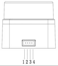
| No | Function | Type | Description | Min. | Typ. | Max. |
|---|---|---|---|---|---|---|
| 1 | TX | Input | Lidar data input | 0V | 3.3V | 3.5V |
| 2 | PWM | Input | Motor Control Signal | 0v | - | 3.3v |
| 3 | GND | Power Supply | Power negative | - | 0v | - |
| 4 | P5V | Power Supply | Power positive | 4.5V | 5V | 5.5V |
The STL-27L uses a standard asynchronous serial port (UART) to send data in one direction with the following transmission parameters:
| Baudrate | Data Length | Stop Bit | Parity Check Bits | Flow Control |
|---|---|---|---|---|
| 921600 | 8 Bits | 1 | No | NO |
【Coordinate System Definition】
The STL-27L commonly follows a left-hand rule coordinate system where the X-axis of the coordinate system (i.e., the 0-angle position) is defined directly in front of the sensor, the origin of the coordinate system is the center of rotation of the distance measurement unit, and the rotation angle increases in a clockwise direction, as shown in the figure below: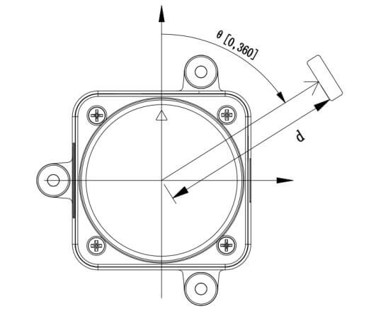
【Optical Windows and Mechanical Dimensions】
The laser emission and reception in the ranging unit of the STL-27L requires an optical window that needs to be exposed in the structure. Partial occlusion of this window by external systems will affect the LIDAR ranging performance to some extent. The following figure shows the dimensions of the optical window (in mm).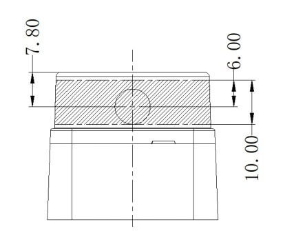
Other mounting dimensions are shown in the following drawings (in mm):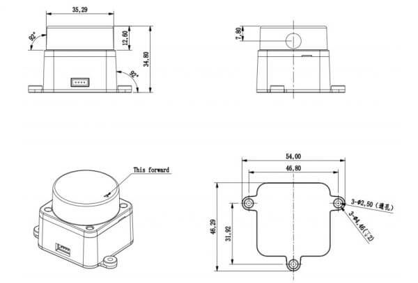
【Adapter Board Secondary Development】
1) The lidar adapter board we provide uses the ESP8266 module to control the lidar start/stop, and we open source the demos in the ESP8266.
2)The lidar adapter board has RX and TX pins (these two are the RX and TX of ESP8266), you need to prepare an extra USB to serial module (e.g. CP2102) to connect the RX, TX, 3V3, and GND on this adapter board.
3) Download the demo.
First, open Arduino IDE, File -> Preferences, and click on the icon at the far right of the line 【Add Board Manager Address】 and add "http://arduino.esp8266.com/stable/package_esp8266com_index.json", If there is another manager address, press Enter to start a line with that address. Board -> Boards Manager, open Boards Manager, input ESP8266 and click Install.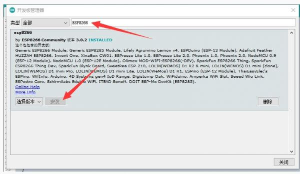
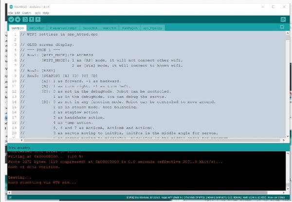
Upload Radar Adapter Board (LiDAR Driver with ESP8266).
Double-click to run LiDAR.ino.
Download the demo.
Click Tools -> Port to remember the existing COM Port without clicking it. The COM displayed here is different from computer to computer, remember the existing COM.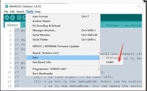
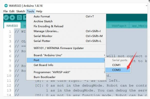
- Use [USB to TTL 4PIN Dupont cable (with chip) (change to 3.3V)] to connect LiDAR Driver with ESP8266 and computer. Hold down G0 while pressing RST to put ESP8266 into download mode.
- Click Tools -> Port and click on this new COM. the new COM that appears here is different for different computers, click on the new COM that appears.
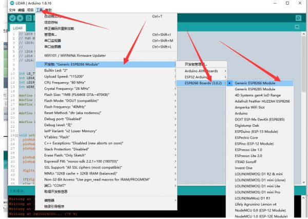
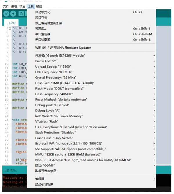
- Select the development board: Generic ESP8266 Module, other settings can be set by default.
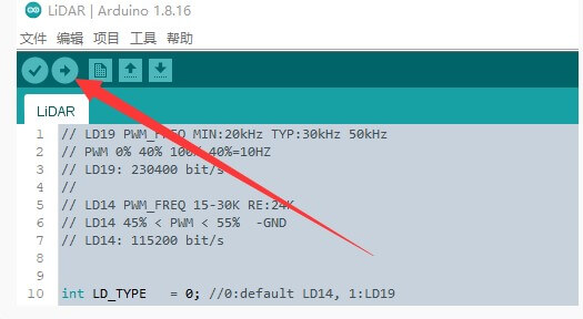
- Click on Upload.
- Wait for the demo to finish uploading. The display shows Leaving... Hard resetting via RTS pin... indicates that the upload was successful.