- sales/support
Google Chat: zj734465502@gmail.com
- sales
+86-0755-88291180
- sales01
sales01@spotpear.com
- sales02
dragon_manager@163.com
- support
services01@spotpear.com
- CEO-Complaints
manager01@spotpear.com
- sales/support
WhatsApp:13246739196
MLX90641-D55 Thermal Camera User Guide
Documents
Demo codes
Instruction
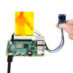
The MLX90641-D55 Thermal Camera is a small size, non-contact, and low-cost IR array thermal imaging camera, with 16 × 12 pixels. It will detect the IR distribution of objects in the field of view, turn the data into the surface temperature of the objects by calculation, and then generate thermal images, for easy integration into miscellaneous industrial or intelligent control applications.
Features
- Adopts MLX90641 far-infrared thermal sensor array, 16 × 12 pixels.
- Communicating via I2C interface, configurable to fast mode (up to 1MHz data rate).
- Noise Equivalent Temperature Difference (NETD) 0.1K RMS@4Hz refresh rate.
- Onboard voltage translator, compatible with 3.3V/5V operating voltage.
- Programable frame rate 0.5~64Hz (0.25~32FPS).
Specification
- Operating voltage: 3.3V/5V
- Operating current: ≈12mA
- Communication interface: I2C (adds 0x33)
- Field of view (Horizontal × Vresertical): 55° x 35°
- Operating temperature: -40℃~125℃
- Target temperature: -40℃~300℃
- Resolution: ±2℃ (ambient temp. 0~50°)
- Refresh rate: 0.5Hz~64Hz (programmable)
- Dimensions: 28mm × 16 mm
- Mounting hole size: 2.0mm
Application
- High-precision non-contact object temperature detection
- Infrared thermal imager, infrared thermometer
- Smart Home, Smart Building, Smart Lighting
- Industrial temperature control, security, intrusion/motion detection
Interface
- Vcc: Connect to 3,3V (MCU)
- GND: Connect to GND (MCU)
- SDA: Connect to SDA pin of I2C interface (MCU)
- SCL: Connect to SCL pin of I2C interface (MCU)
Communication protocol
The communication protocol of MLX90640-D55 Thermal Camera is I2C, which supports I2C high-speed mode (up to 1MHz), and can only be used as a slave device on the I2C bus. The SDA and SCL ports can withstand 5V voltage and can be directly connected to the 5V I2C bus , the device address of the module can be programmed, there can be up to 127 addresses, the factory default value is 0x33. Like the general I2C bus, there are three types of signals in the process of data transmission: start signal, end signal and response signal.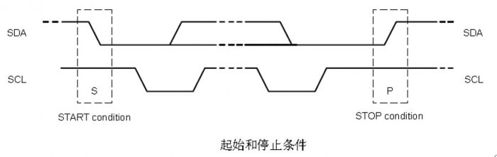
Start signal: SCL is high level, SDA is converted from high level to low level.
End signal: SCL is high level, SDA is converted from low level to high level.
It can be seen that the start signal and the end signal are completed when the SCL bus is high.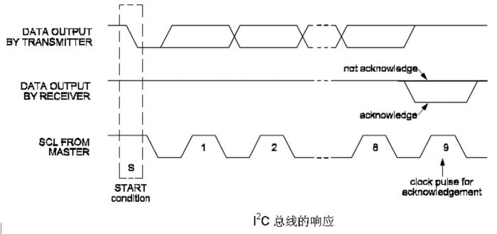
Response signal: During the 9th clock period after each byte transmission, the sending data end device releases the SDA bus, and the receiving data end device pulls down the SDA bus to indicate the received byte (ACK), or the SDA bus is high Ping no acknowledgment (NoACK).
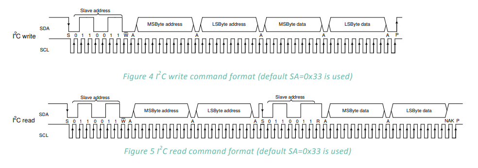
Device Address: The master addresses the slave by sending a 7-bit slave address after a START condition. The first seven bits are dedicated to this address, and the 8th is the read/write (R/W) bit. This bit indicates the transfer direction, The high level means that the master will read data from the slave, and the low level means that the master will send data to the slave.
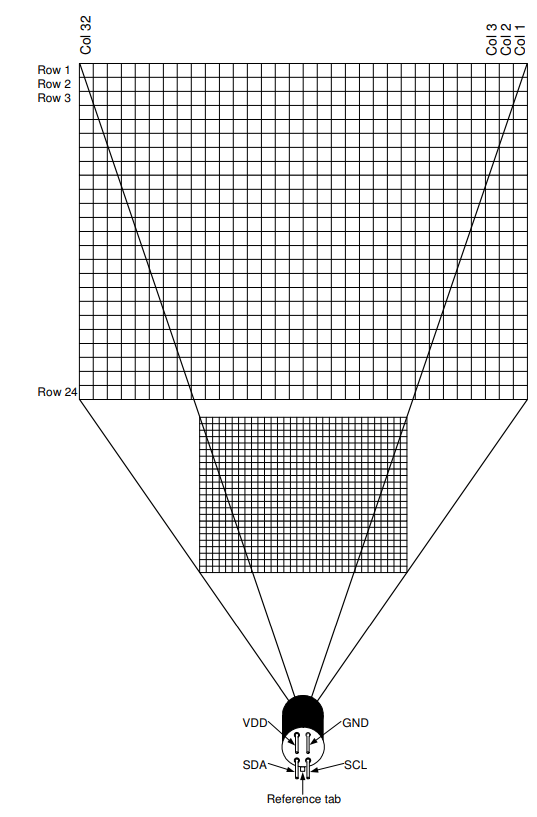
The MLX90640-D55 Thermal Camera consists of a total of 768 IR sensors (also called pixels). The row and column positions of each pixel are identified as Pixel(i, j), where i is its row number (from 1 to 24), and j is Its column number (from 1 to 32), the pixel specific to a certain plane can refer to the above figure.
- It should be noted that the original sensor is allowed to have less than 4 dead points when the sensor leaves the factory,and each dead point is marked in the EEPROM table, so the module may have a certain probability of dead points, that is to say, this cannot be used as a return. According to the goods, the original recommendation for this is to use the average value of adjacent pixels instead.
Memory and registers
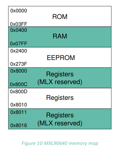
The above picture shows the distribution of RAM area and control registers of MLX90640, in which there are two data modes in RAM area, and EEPROM is used to store calibration constants and device configuration parameters, as shown in the following figure:
Refresh rate
This module support 8 kinds of refresh rate, up to 64Hz. The refresh rate is configured by registers 1-0x800D
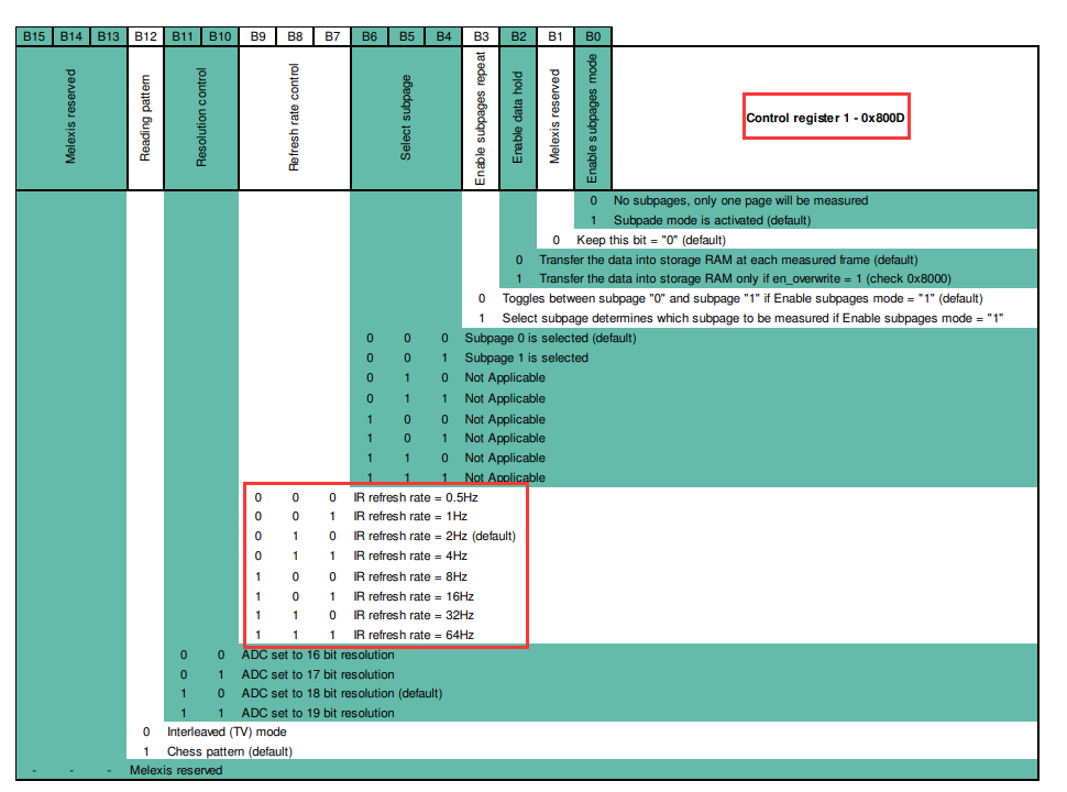
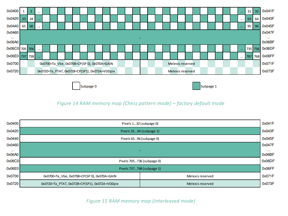
The settings of the 8 refresh rates are determined by bit 7, bit 8, and bit 9 of the control register 1 (0x800D), among which there are chess mode (factory default setting), TV interleave mode, as shown below:
: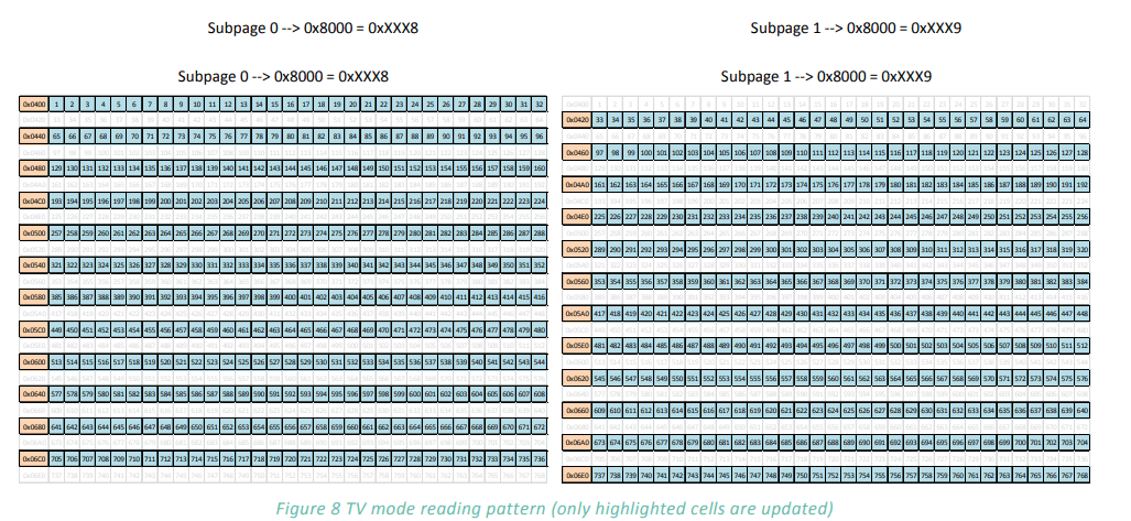
TV interleave mode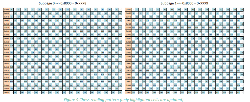
The array frame is divided into two subpages and depending on bit 12 in “Control register 1” (0x800D). As a standard the MLX90640 is calibrated in Chess pattern mode, this results in better-fixed pattern noise behavior of the sensor when in chess pattern mode. For best results, we advise to use chess pattern mode.
Temperature measurement principle and measurement distance
Temperature measurement principle
What is infrared temperature measurement?(quoted from OPTRIS)
Next to time, temperature is the most frequently measured physical property. Infrared temperature measurement devices define the temperature according to the radiation law of Planck and Boltzmann through infrared radiation released by the measured object. But how does non-contact temperature measurement work?
Each body, with a temperature above the absolute zero of 0 K (-273.15°C) emits an electromagnetic radiation from its surface, which is proportional to its intrinsic temperature. A part of this radiation is infrared radiation which is used to measure temperature. The radiation of the body penetrates the atmosphere and can be focused on a detector element with the help of a lens. The detector element generates an electrical signal proportional to the radiation. This signal is amplified and, using successive digital signal processing, is transformed into an output signal proportional to the object temperature. The measuring value can be shown on a display or released as a signal.
The emissivity ε (Epsilon) has a central importance, if the temperature is measured through radiation. The emissivity defines the relation of the radiation value in real and of the black body. This is maximal 1 for a black body. But only few bodies meet the ideal of the black body. For the calibration of sensors contact faces of radiators are generally used, which consists of the favoured wave length of 0.99.
Many bodies have a constant emissivity regarding the wave length, but do emit far less radiation than black bodies. They are called grey bodies. Bodies whos emissivity depends on the temperature and the wave length, such as metals, are called selective radiator. The missing radiation part is compensated in both cases through the definition of emissivity. When using a selective radiator, one needs to bear in mind the measured wave length (short-wave for metal).
The infrared sensor receives the emitted radiation from the object surface, but also reflected radiation form the surroundings and perhaps penetrated infrared radiation from the measuring object.
Measurement distance
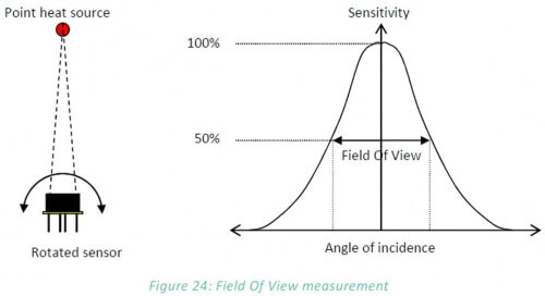
The FOV of this module is determined by 50% radiation signal which is received by the thermopile, it is also influenced by the main axis of the sensor. The temperature measured is the weighted average of the detected object's temperature in FOV. To improve the accuracy, you should make sure that the detected object is in the FOV totally.
For the relationship between the measurement distance and the field of view, please refer to the calculation formula shown in the following figure mentioned by Melexis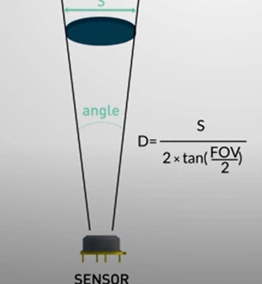
Examples
Raspberry Pi
1. When using the sensor, please pay attention to avoid direct contact with the onboard IC devices in your hands. Pay attention to prevent static electricity and check the power supply to prevent reverse connection before powering on.
2. When the sensor is working, please avoid excessive vibration and do not plug or unplug cables. Since MLX90640 has EEPROM, it will easily be damaged by vibration and a hot plug.
- Hardware connection
| Raspberry Pi | MLX90640 Thermal Camera |
|---|---|
| 5V | 5V |
| GND | GND |
| SDA(BCM2) | SDA |
| SCL(BCM3) | SCL |
Use
- Please use the 2021-05-07-raspios-buster-armhf.zip system to test.
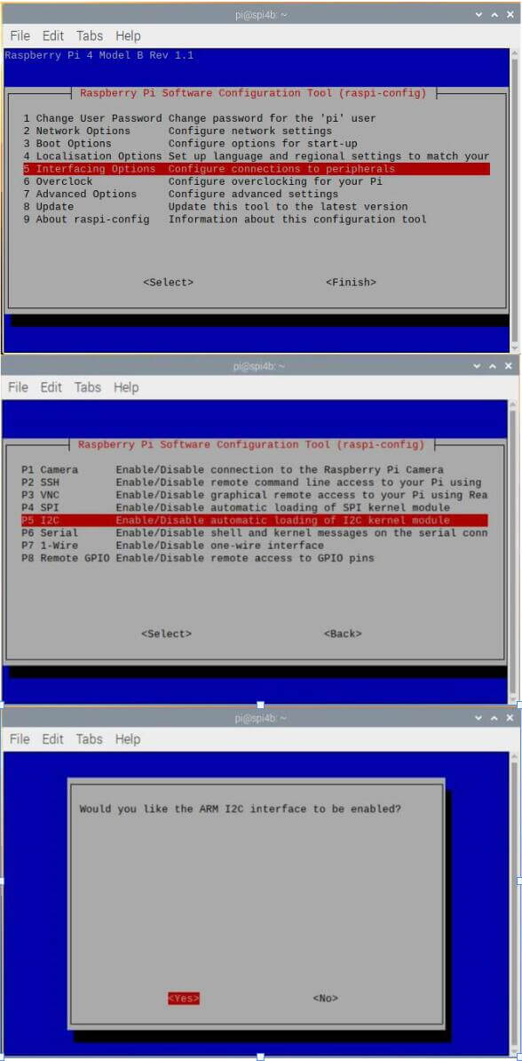
Enter the following commands in the Raspberry Pi terminal. The first command enables hardware I2C. If it has been set, you can skip this command. The relevant settings are as follows:
sudo raspi-config
cd ~
wget https://files.waveshare.com/upload/c/c9/Mlx90640_thermal_camera.zip
unzip Mlx90640_thermal_camera.zip
cd mlx90640_thermal_camera/RaspberryPi/cpp/
chmod +x install.sh
sudo ./install.sh
make
sudo ./main
- If the detection has been delayed, you can try to modify the i2c speed in the config.txt file.
sudo nano /boot/config.txt
- Add the line below to the config.txt file, reboot, and check it again.
dtparam=i2c1_baudrate=1000000
STM32
1. When using the sensor, please pay attention to avoid direct contact with the onboard IC devices in your hands. Pay attention to prevent static electricity and check the power supply to prevent reverse connection before powering on.
2. When the sensor is working, please avoid excessive vibration and do not plug or unplug cables. Since the MLX90640 has EEPROM, it will easily damaged by vibration and hot plug.
- Hardware connection
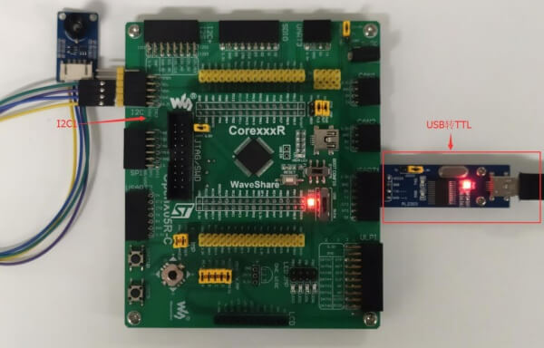
| STM32 | MLX90640 Thermal Camera |
|---|---|
| 5V | 5V |
| GND | GND |
| SDA(PB11) | SDA |
| SCL(PB10) | SCL |
ESP32
1. When using the sensor, please pay attention to avoid direct contact with the onboard IC devices by your hands, Pay attention to prevent static electricity, and check the power supply to prevent reverse connection before powering on.
2. When the sensor is working, please avoid excessive vibration and do not plug or unplug cables. Since the MLX90640 has EEPROM, it will easily be damaged by vibration and hot plug.
- Hardware connection
| ESP32 | MLX90640 Thermal Camera |
|---|---|
| 5V | 5V |
| GND | GND |
| SDA(P21) | SDA |
| SCL(P22) | SCL |