- sales/support
Google Chat: zj734465502@gmail.com
- sales
+86-0755-88291180
- sales01
sales01@spotpear.com
- sales02
dragon_manager@163.com
- support
services01@spotpear.com
- CEO-Complaints
manager01@spotpear.com
- sales/support
WhatsApp:13246739196
- HOME
- >
- ARTICLES
- >
- Common Moudle
- >
- ESP
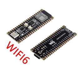
ESP32-C6-Pico Tutorial
material
software
Programming software
serial port
Flash burning
Bluetooth debugging
Schematic diagram
Data sheet
ESP32-C6
- ESP32-C6-MINI-1 Technical Specification (Chinese)
- ESP32-C6 Technical Reference Manual (Chinese)
- ESP32-C6 series chip technical specifications (Chinese)
- ESP32-C6-MINI-1 Datasheet (English)
- ESP32-C6 Technical Reference Manua (English)
- ESP32-C6 Series Datasheet (English)
TCA9554PWR
Official documentation
ESP32 official documentation
【Product Introduction】
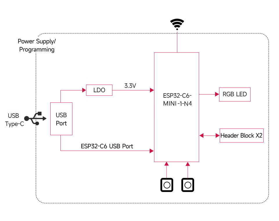
[ ] E SP32-C6-Pico is a small microcontroller development board equipped with a variety of digital interfaces.
[] In terms of hardware, the ESP32-C6-MINI-1 module is used, which is equipped with a RISC-V 32-bit single-core processor, supports a clock frequency of up to 160 MHz, and has built-in 320KB ROM, 512KB HP SRAM, 16KB LP SRAM and 4 MB flash; the pin interface is compatible with the Raspberry Pi Pico development board and can be expanded to a variety of peripheral devices, making it more convenient to use.
[] In terms of software, you can choose the ESP-IDF development environment or Arduino IED for development, so you can get started easily and quickly and apply it to products.
【Product Features】
[] Using ESP32-C6-MINI-1 module, equipped with RISC-V 32-bit single-core processor, supporting clock frequency up to 160 MHz
[] Integrated 320KB ROM, 512KB HP SRAM, 16KB LP SRAM and 4MB Flash memory
[] Integrated 2.4GHz Wi-Fi 6 and Bluetooth LE dual-mode wireless communication with superior radio frequency performance
[] Using USB Type-C interface, no need to worry about plugging forward and reverse
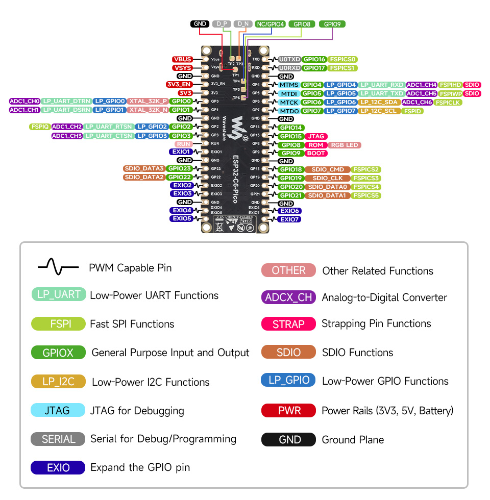
[] Leads to rich peripheral interfaces, and the pin interface is compatible with the Raspberry Pi Pico development board, with strong compatibility and scalability.
[] Stamp hole design, can be directly welded and integrated into the base plate designed by the user.
[] Supports multiple low-power working states and can adjust the balance between communication distance, data rate and power consumption to meet the power consumption requirements of various application scenarios
[] Please note that to ensure the functional integrity of the device, be sure to call the provided WS_TCA9554PWR file to set GPIO22 (SDA) and GPIO23 (SCL) as I2C functions for GPIO expansion
[] Please note that GPIO22 (SDA) and GPIO23 (SCL) have been used in TCA9554PWR. Currently, only I2C slave devices can be connected to these pins. These two pins are not allowed to be used for other functions.
【Functional block diagram】
【Resource interface】

【Pin distribution】
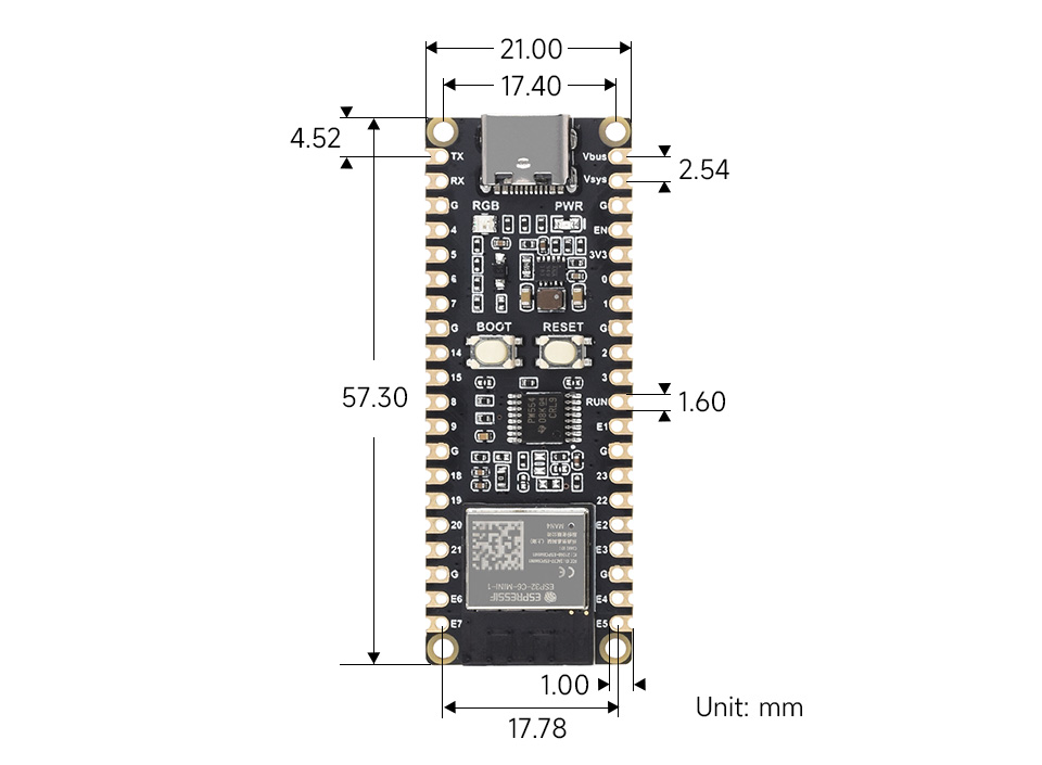
【Product Size】
[TCA9554PWR function description]
[] Please note that the corresponding library files must be referenced when using EXIO1 ~ EXIO7 (add the TCA9554PWR library under VScode, add the TCA9554PWR library under Arduino IDE)
| function function | function name | Function parameters | Function |
| Initialize TCA9554PWR | TCA9554PWR_Init | uint8_t PinState | Initialize all pins of TCA9554PWR in PinState mode |
|---|---|---|---|
| Operation register | Read_REG | uint8_t REG | Read the value in the REG register of TCA9554PWR |
| Write_REG | uint8_t REG,uint8_t Data | Write data Data to the REG register of TCA9554PWR | |
| Initialize EXIO mode | Mode_EXIO | uint8_t Pin,uint8_t State | Set the pin mode of TCA9554PWR |
| Mode_EXIOS | uint8_t PinState | Set the mode of all pins of TCA9554PWR | |
| Read EXIO level status | Read_EXIO | uint8_t Pin | Read the input level of the Pin of TCA9554PWR |
| Read_EXIOS | void | Read the input levels of all pins of TCA9554PWR | |
| Set EXIO output level | Set_EXIO | uint8_t Pin,uint8_t State | Set the output level of the Pin of TCA9554PWR |
| Set_EXIOS | int8_t PinState | Set the output levels of all pins of TCA9554PWR | |
| Flip EXIO level state | Set_Toggle | uint8_t Pin | Flip the output level of Pin of TCA9554PWR |
[Used under ESP-IDF]
The following development systems default to Windows. It is recommended to use the VSCode plug-in for development.
[Developed using VSCode plug-in]
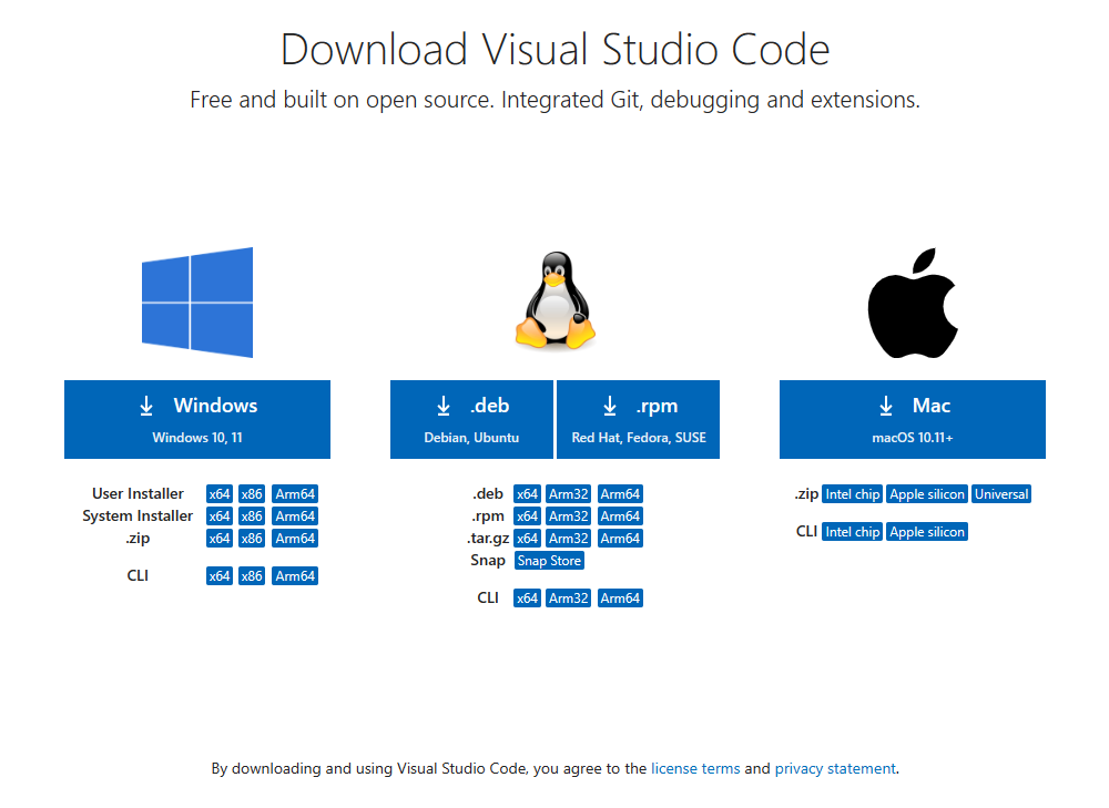
[] Install VSCode
[] Open the download page of VSCode official website , select the corresponding system and system number to download
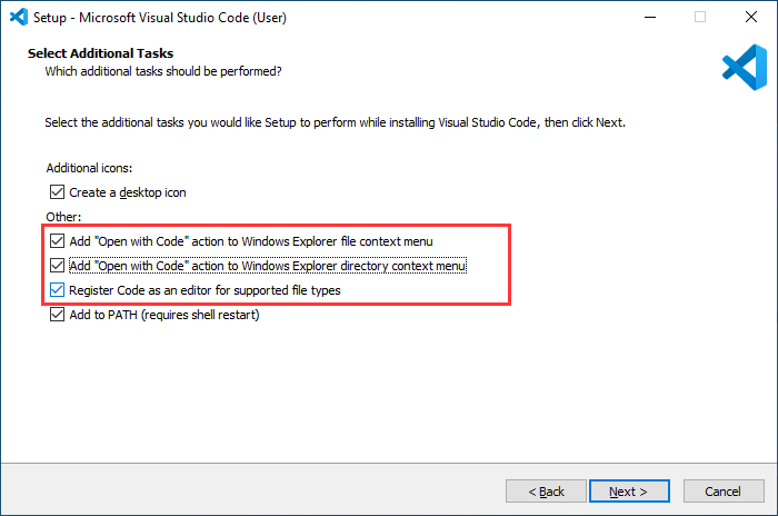
[] After running the installation package, the rest can be installed by default. However, for the sake of subsequent experience, it is recommended to check items 1, 2, and 3 in the box here.
[] After the first and second items are enabled, VSCode can be opened directly by right-clicking the file or directory, which can improve the subsequent use experience.
[] After the third item is turned on, when selecting the opening method, you can directly select VSCode
[Install Espressif IDF plug-in]
[] Note: The latest version of the current plug-in is V1.6.4. For a consistent experience, users can choose the same version as us.
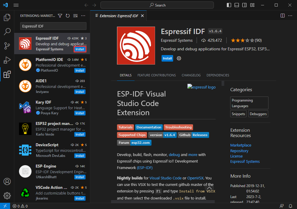
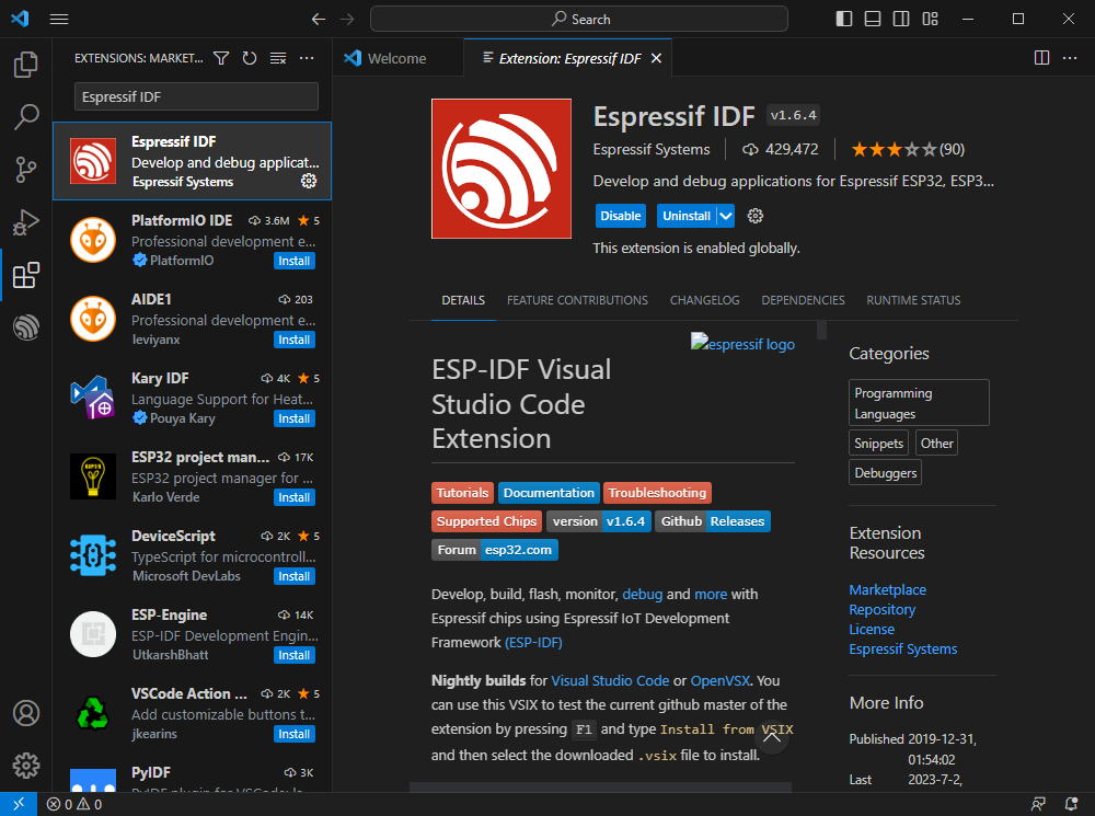
[] Open VSCode, use the shortcut key Shift+Ctrl+X to enter the plug-in manager
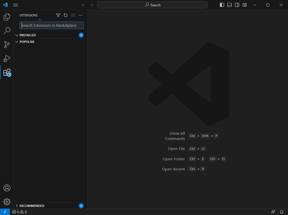
In the search bar, enter Espressif IDF, select the corresponding plug-in and click install.
Use the shortcut key F1 and enter
esp-idf: configure esp-idf extension
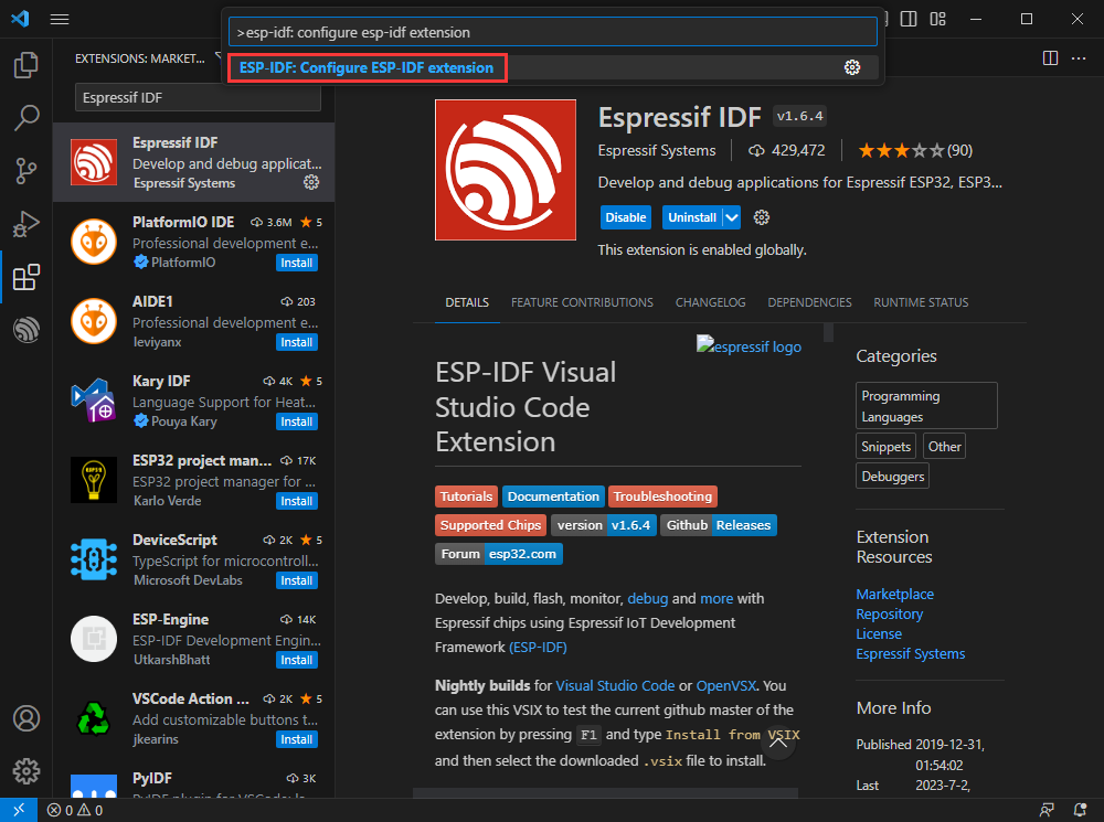
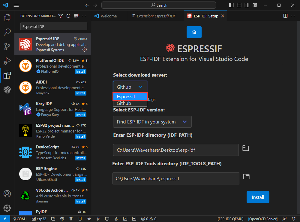
Select express (this tutorial is for first-time installation users, so it only describes the first general installation tutorial)
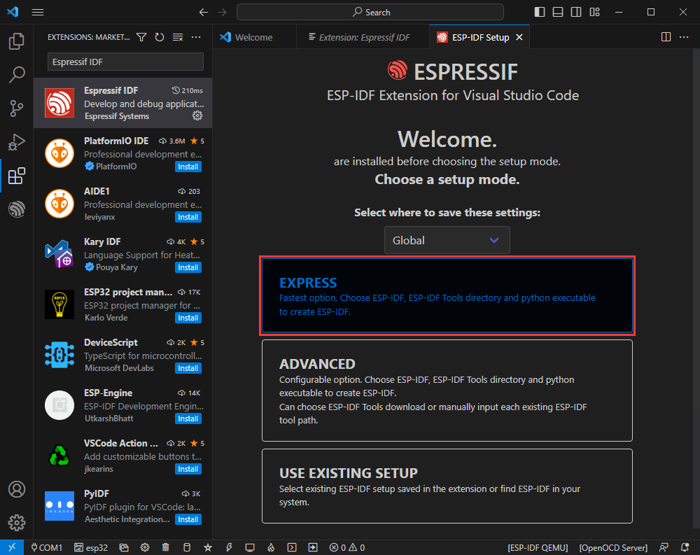
Select the download server. We recommend that domestic users use Espressif as your download server.
Select the current ESP-IDF version, we choose the latest V5.1.1 (note that ESP-IDF only supports ESP32-C6 from V5.1 version)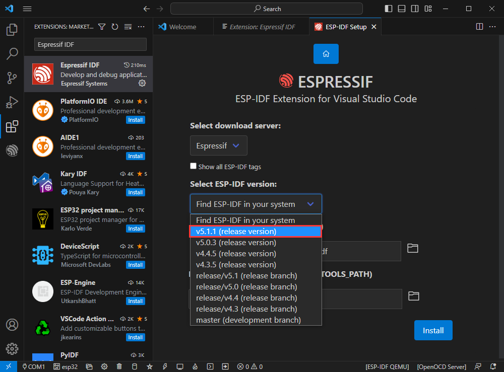
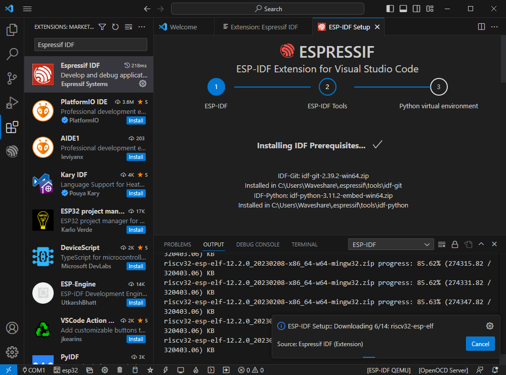
The following two are respectively the ESP-IDF container installation address and the tool installation address required for ESP-IDF.
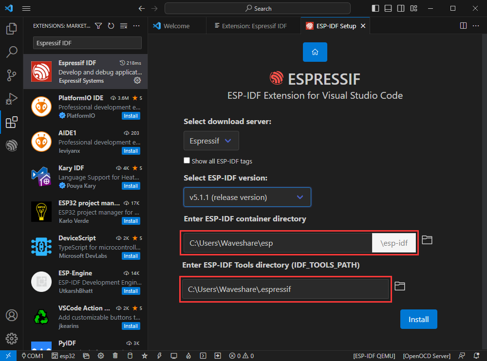
[] Note: If ESP-IDF has been installed before or failed, please be sure to completely delete the file or create a new non-Chinese path.
[] After the configuration is completed, click install to download.
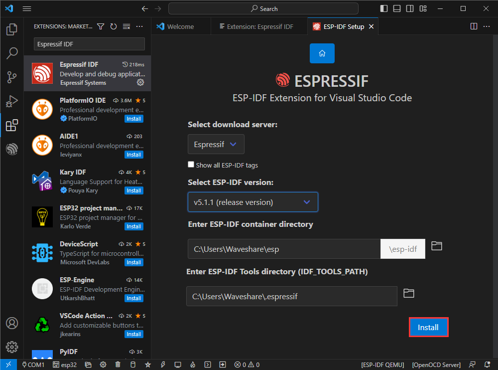
Enter the download page, which will automatically install the corresponding tools and environment, just wait a moment.
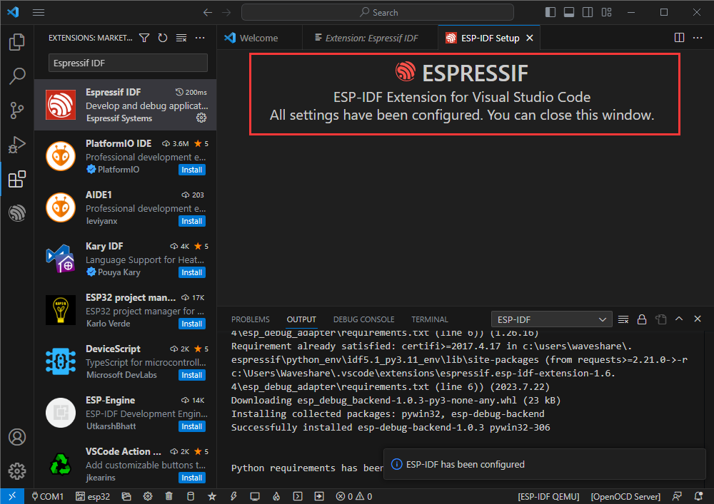
After the installation is completed, you will enter the following interface, indicating that the installation is complete.
[Official routine usage tutorial]
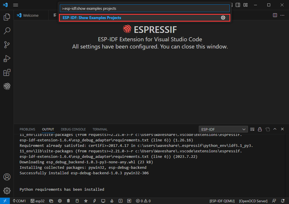
【Create routine】
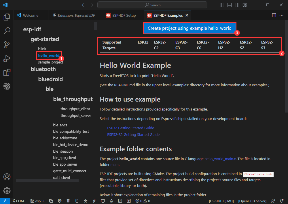
Use the shortcut key F1 and enter
esp-idf:show examples projects
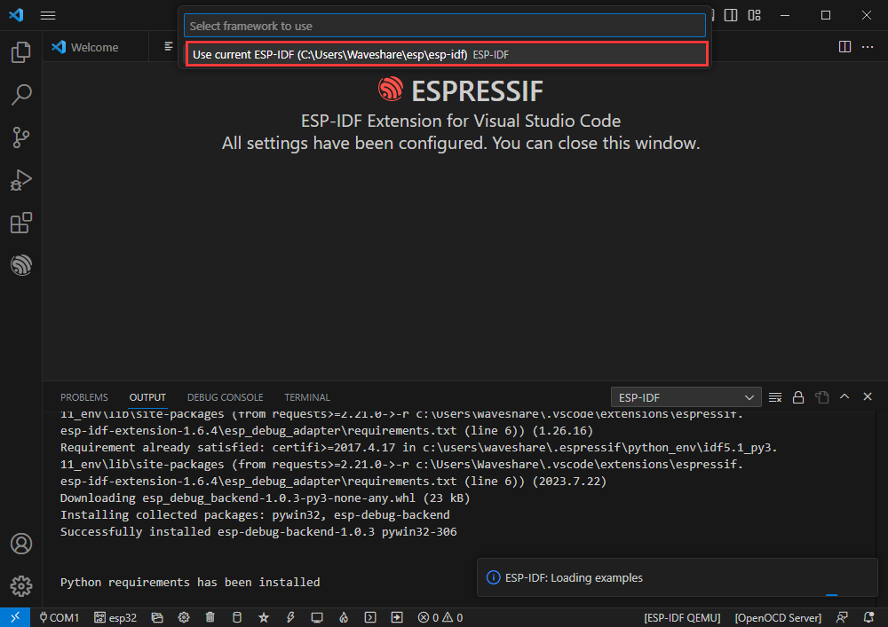
Select your current IDF version
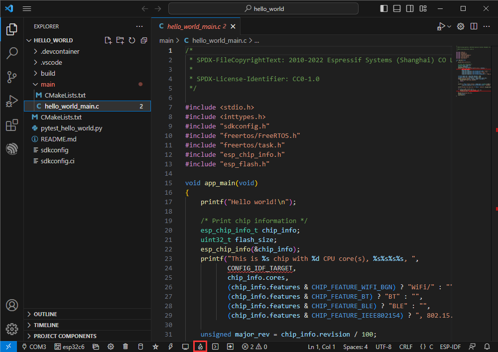
[Take the Hello world routine as an example]
[] Select the corresponding routine
[] The readme will explain what chip the routine is suitable for (the following describes how to use the routine and the file structure, which is omitted here)
[] Click to create a routine
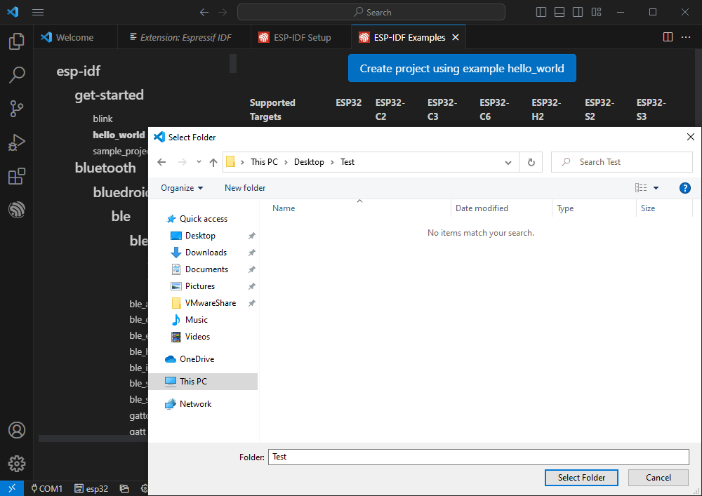
Select the path to place the routine. It is required that there is no folder with the same name as the routine.
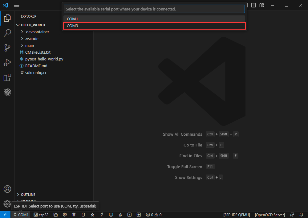
[Modify COM port]
[] The corresponding COM port is displayed here. Click to modify the corresponding COM port.
[] Please select according to the COM port corresponding to the device.
[] If the download fails, please click the reset button for more than 1 second and wait for the PC to re-recognize the device before downloading again.
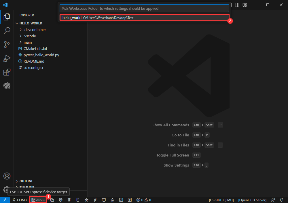
Select the project or routine to use
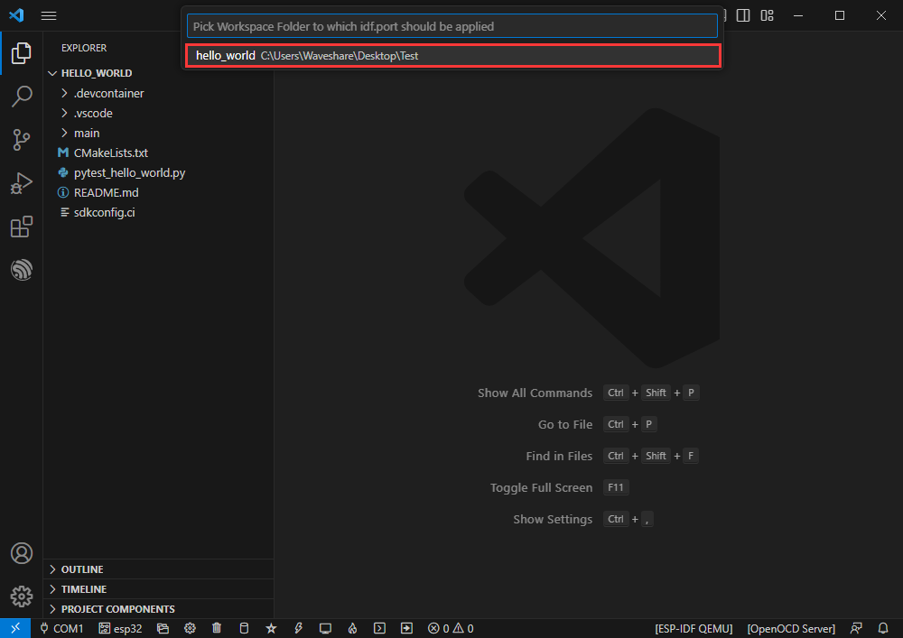
[] Then our COM port is modified.
Modify driver object
[] Displayed here is the driver object used. Click to modify the corresponding driver object.
[] Select the project or routine to use
Please wait for a while after clicking
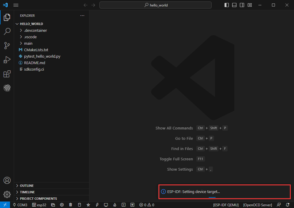
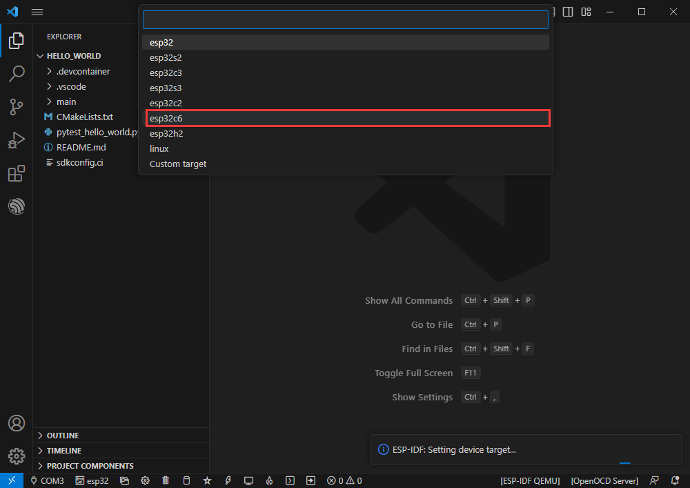
Select the object we need to drive, that is, our main chip is ESP32C6
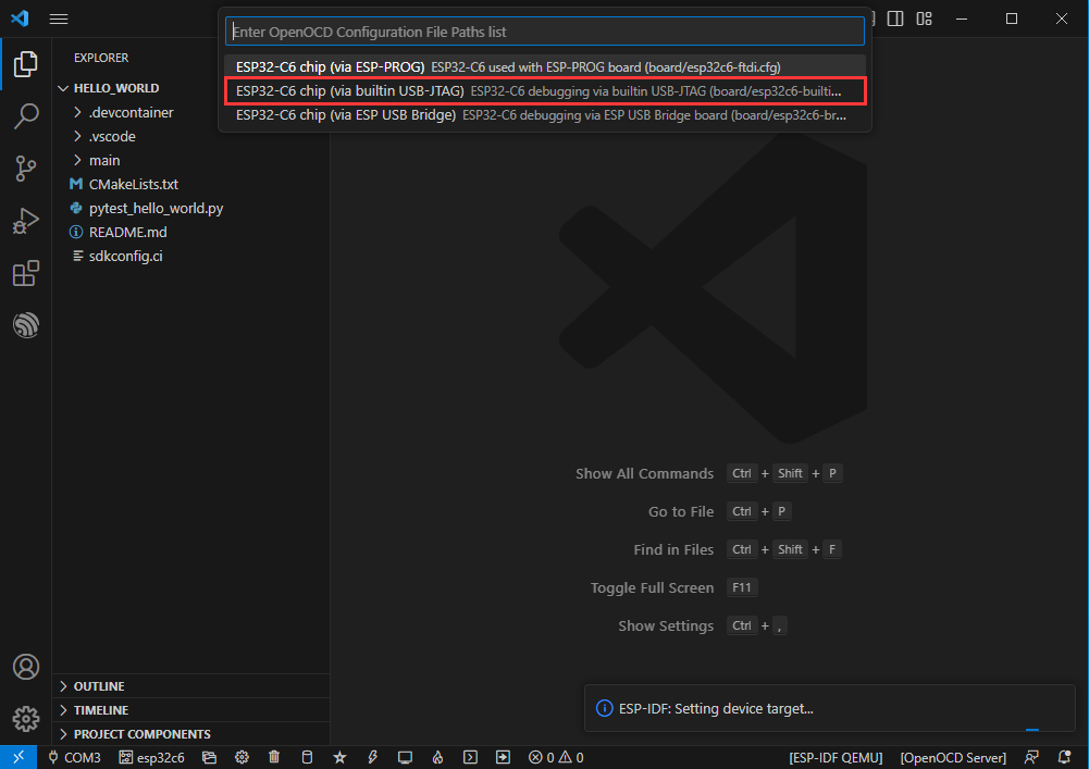
Select the path of openocd. It has no effect on us here, so we can choose any one.
Introduction to other status bars
①SDK configuration editor, many functions and configurations of ESP-IDF can be modified in it
② Clean all, clear all compiled files,
③Compile
④Current download method, default is UART
⑤ Burn the current firmware, please do it after compilation
⑥Open the serial port monitor to view serial port information
⑦ Compile, burn, and open the serial monitor integrated button (most commonly used during debugging)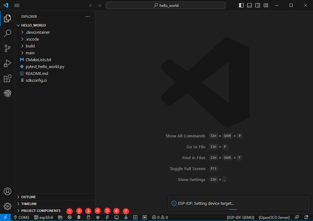
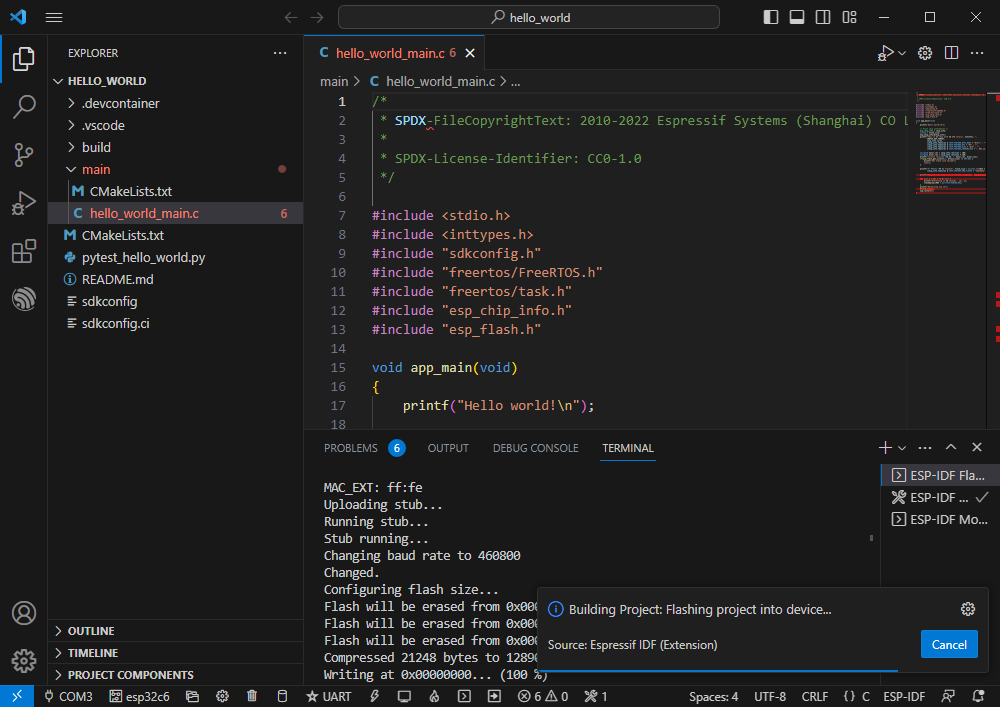
Compilation, burning, serial port monitoring
Click the compile, burn, and open serial monitor buttons we introduced earlier
Compilation may take a long time to complete, especially the first time.
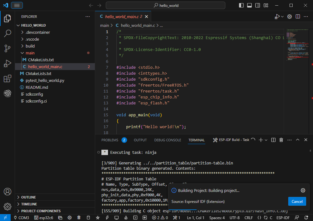
During this process, ESP-IDF may occupy a large amount of CPU resources and therefore may cause system lags.
If it is the first time to burn a program for a new project, you will need to choose the download method and select UART.
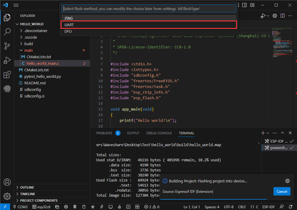
You can also modify the download method later (click to pop up the options)
Because of the onboard automatic download circuit, automatic downloading is possible without manual operation.
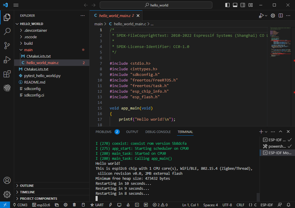
After the download is successful, it automatically enters the serial port monitor. You can see the corresponding information output by the chip and prompts to restart after 10 seconds.
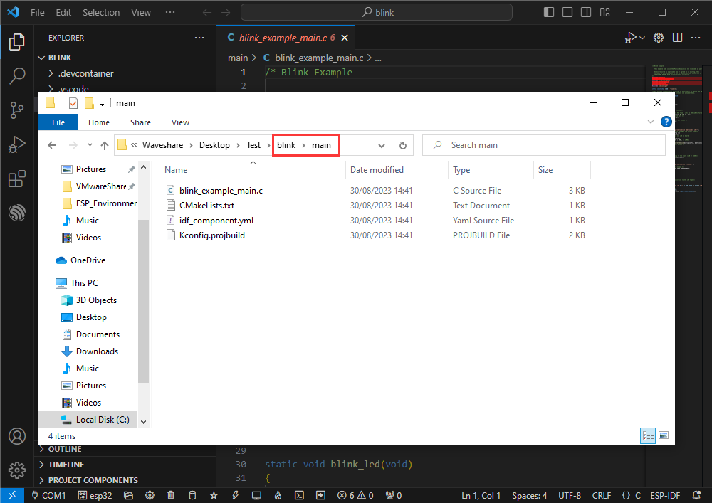
Add EXIO control program under VScode
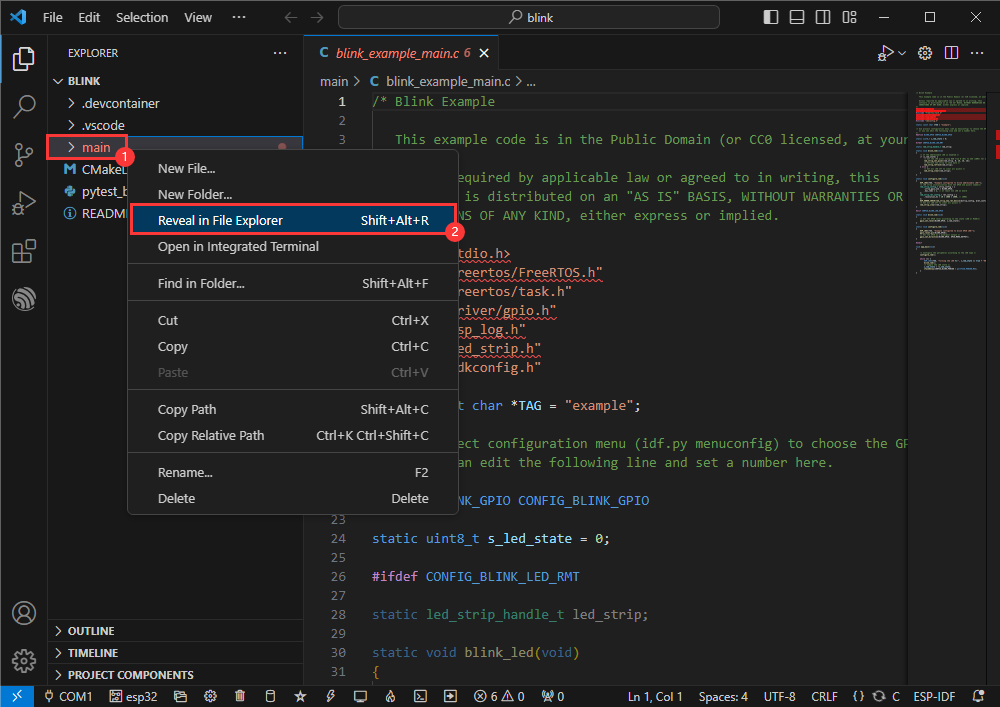
[] Use the official example blink to demonstrate the modification steps
[] Official example path: get-started -> blink
[] Create the official example blink according to the tutorial above
[] Enter the project main folder directory
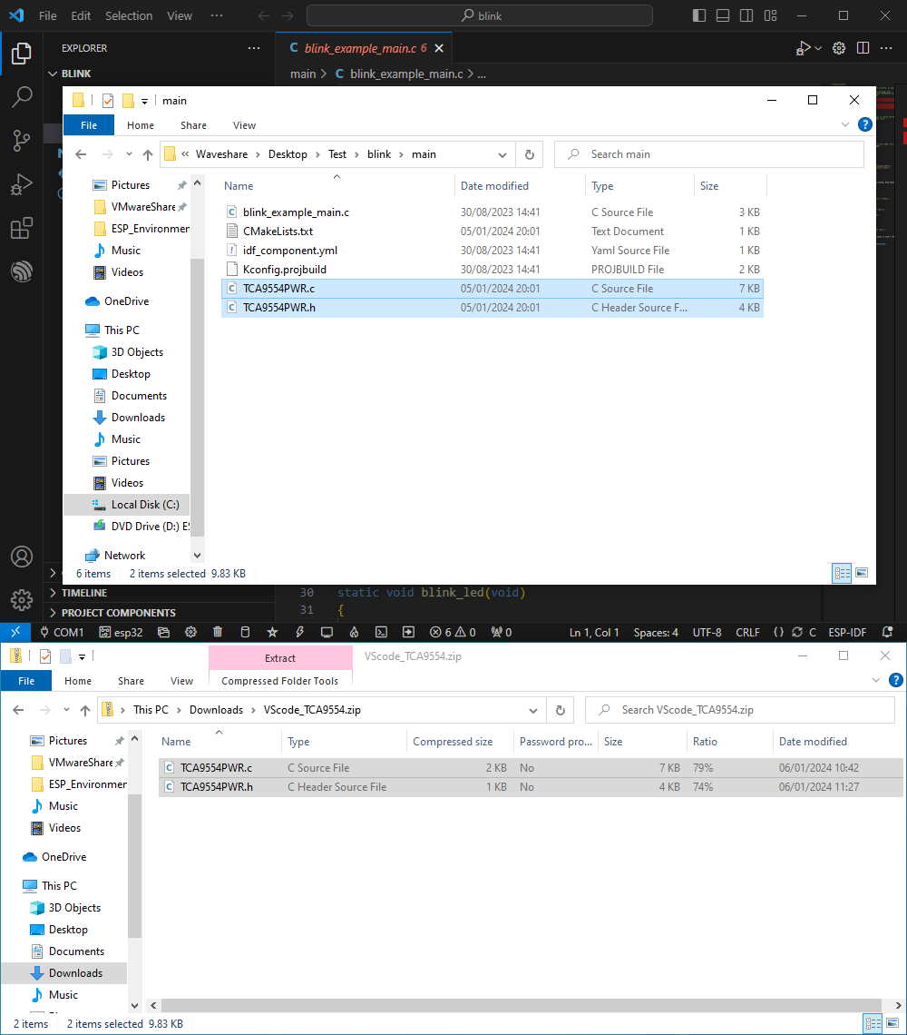
Download EXIO control program
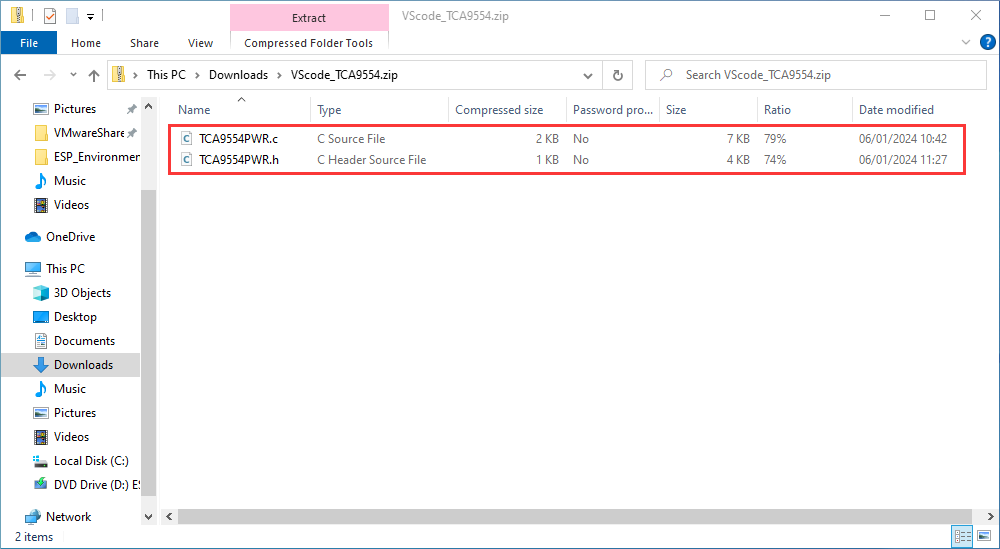
Copy the EXIO control program to the main folder
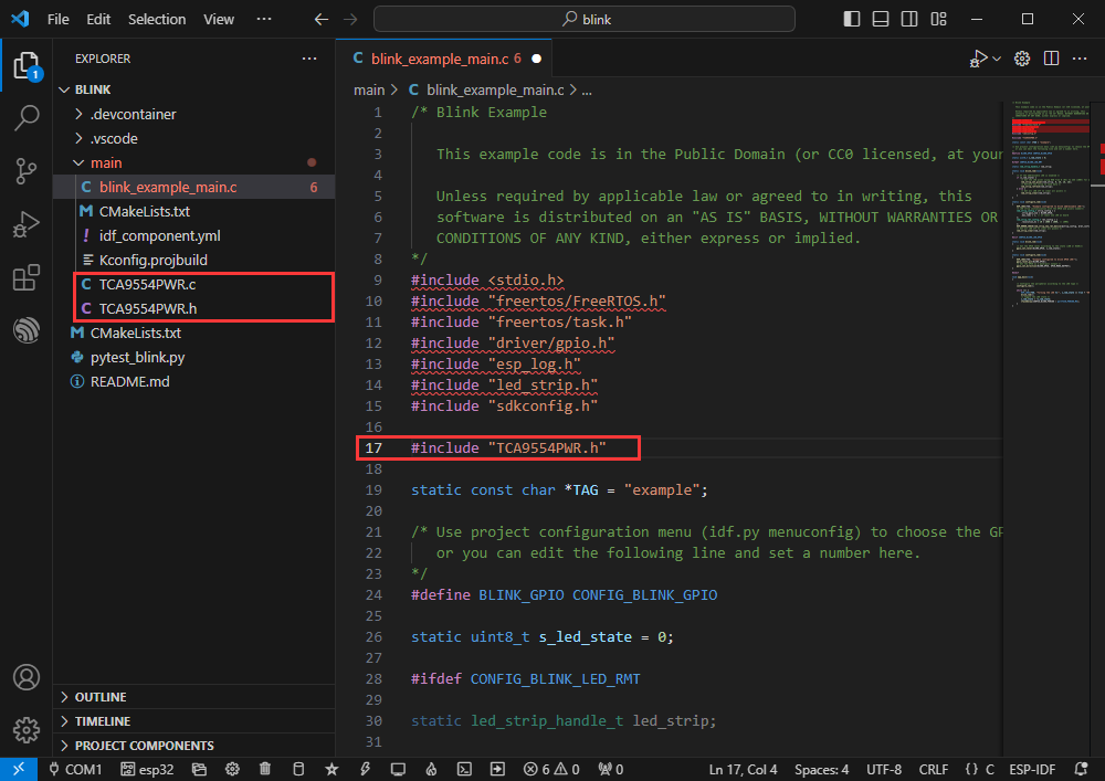
Reference TCA9554PWR file
#include "TCA9554PWR.h"
The control program after TCA9554PWR is currently initialized
As shown below, add the following program to realize EXIO1~EXIO7 output high level in sequence
uint8_t count = 0;
TCA9554PWR_Init(0x00);
Set_EXIOS(0x01<<count); // Set 7 EXIO loops to output high levels
count++;
if(count == 7)
    count = 0;
uint8_t State = Read_EXIO(TCA9554_EXIO3); // Read EXIO3's input level
printf("EXIO3: %d\r\n",State);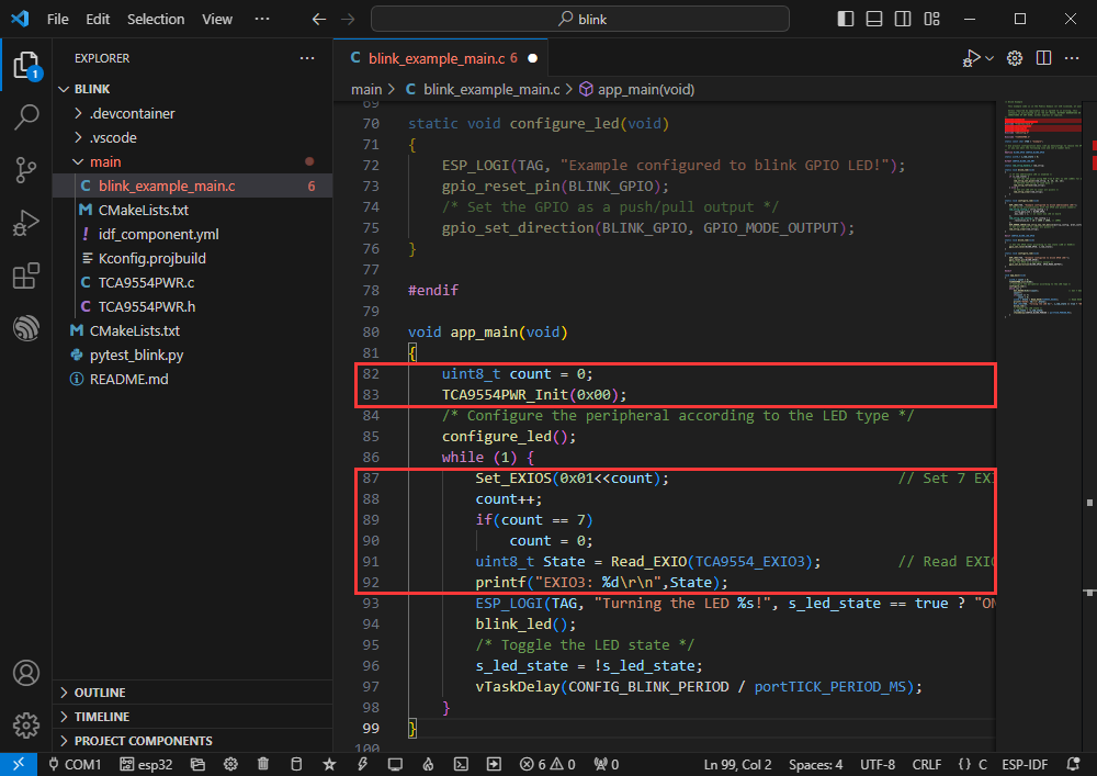
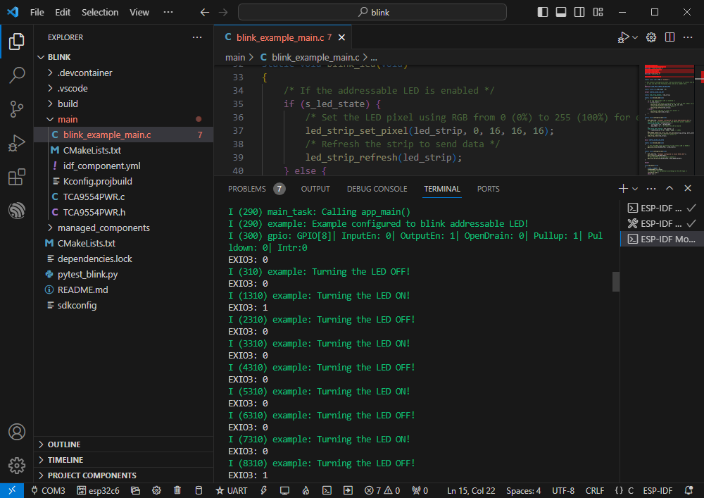
Select the COM port and driver object to burn the program
The effect is as follows
【Example Demonstration】
Hello Word
[] Official example path: get-started -> hello_world
[] Example effect: Output Hello world! in the TERMINAL window at 10-second intervals.
Software operation
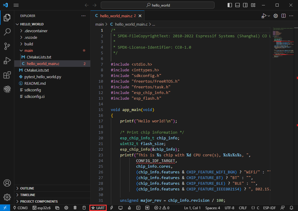
[] Create the official example hello_world according to the tutorial above
[] The program is compatible with ESP32-C6 and can be used without modifying the program content.
[] Modify the COM port and driver object, click compile and burn to run the program
GPIO
[] Official example path: peripherals -> gpio -> generic_gpio
[] Example effect: LED flashes at 1 second intervals
Hardware connection
| ESP32-C6 | led |
| GPIO18 (or GPIO19) | LED+ |
| GND | LED- |
Software operation
[] Create the official example generic_gpio according to the tutorial above (Create Example)
[] The program is compatible with ESP32-C6 and can be used without modifying the program content.
[] Modify the COM port and driver object, click compile and burn to run the program
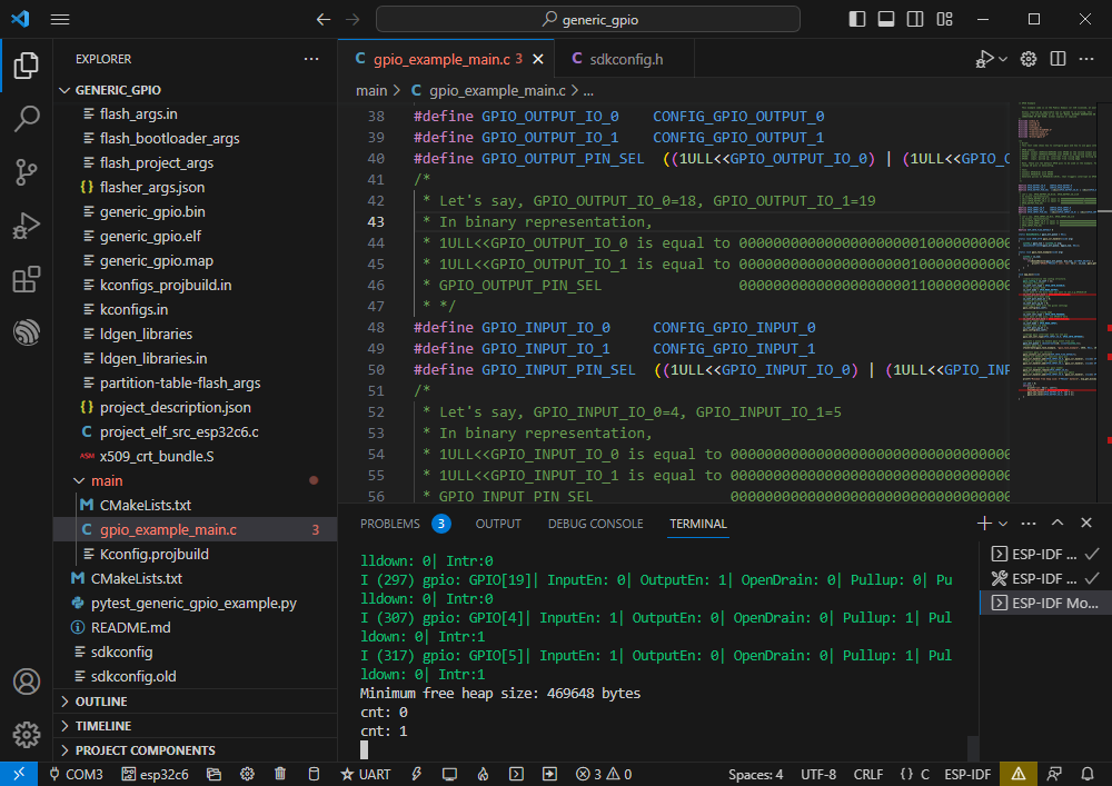
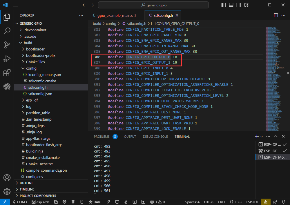
Enter the program macro definition location to view the actual processed GPIO
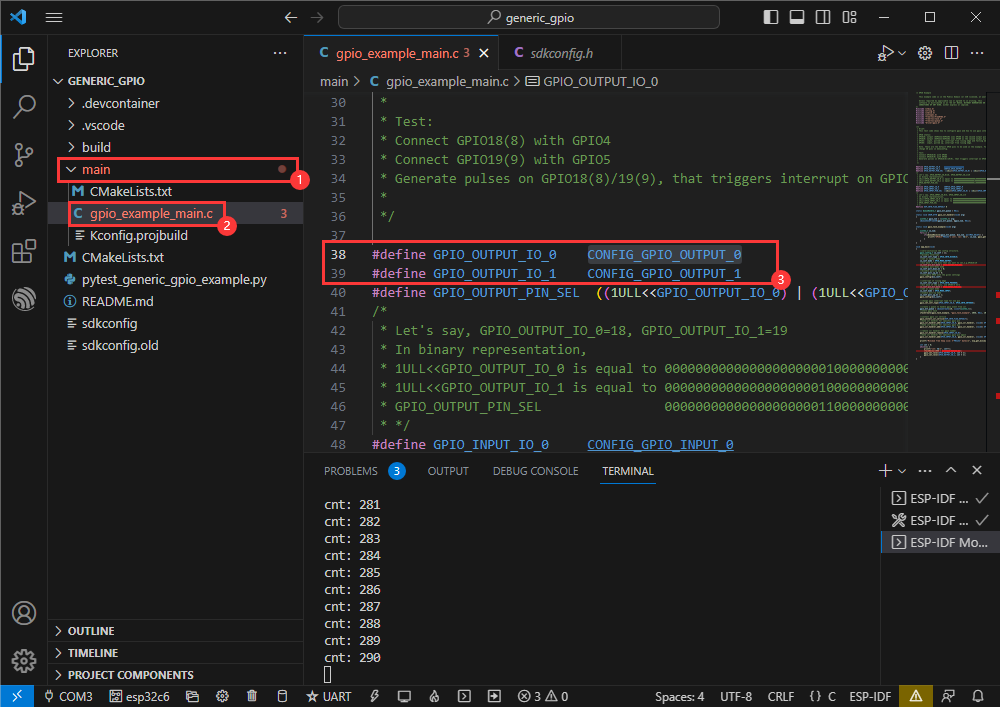
Right click and enter the GPIO definition location
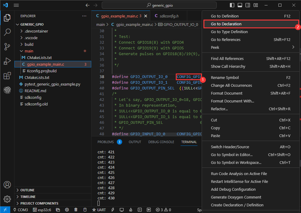
The actual processed GPIOs are GPIO18 and GPIO19
RGB
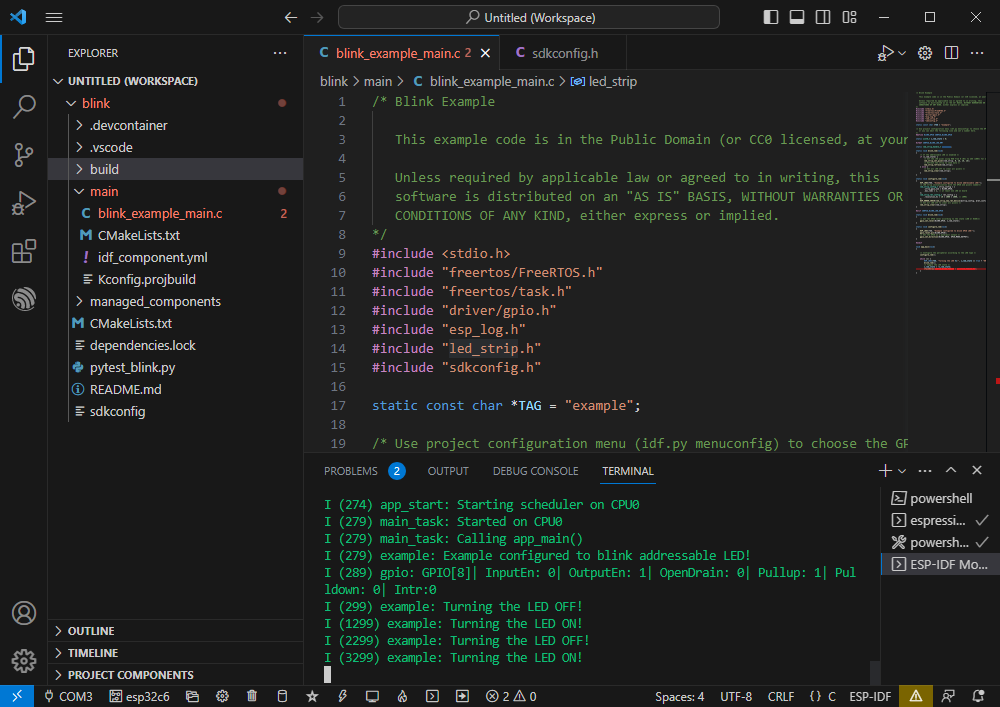
[] Official example path: get-started -> blink
[] Example effect: Onboard RGB lamp beads flash at 1 second intervals
Software operation
[] Create the official example blink according to the tutorial above
[] The program is compatible with ESP32-C6 and can be used without modifying the program content.
[] Modify the COM port and driver object, click compile and burn to run the program
UART
[] Official example path: peripherals -> uart-> uart_async_rxtxtasks
[] Example effect: short-circuiting GPIO4 and GPIO5 to perform UART data self-sending and receiving
Hardware connection
| ESP32-C6 | ESP32-C6 (same block) |
| GPIO4 | GPIO5 |
Software operation
[] Create the official example uart_async_rxtxtasks according to the tutorial above
[] The program is compatible with ESP32-C6 and can be used without modifying the program content.
[] Modify the COM port and driver object, click compile and burn to run the program
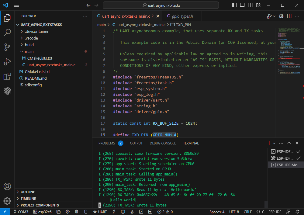
Make hardware connections based on the GPIO used
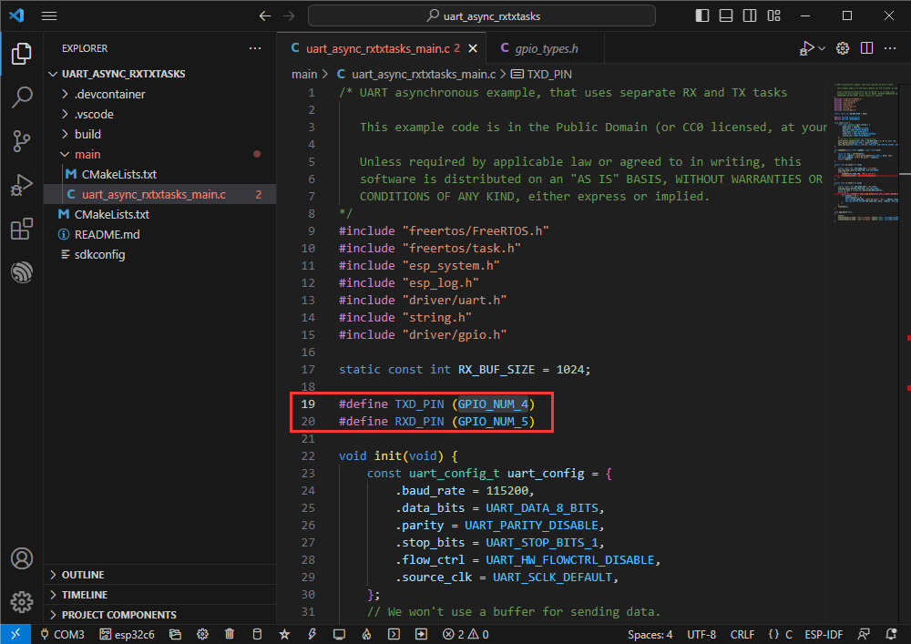
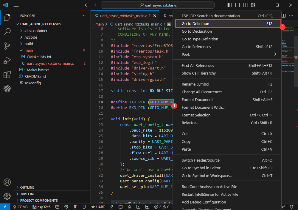
You can go to the definition file to view the actual used GPIO (select GPIO_NUM_4 -> right click -> Go to Definition)
I2C
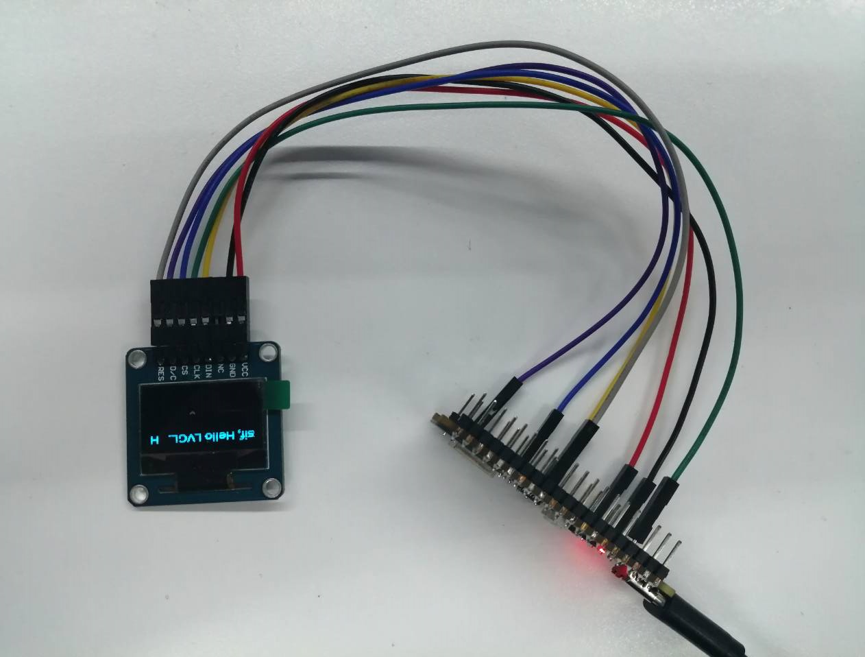
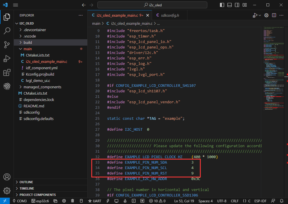
[] Official example path: peripherals -> lcd-> i2c_oled
[] Example effect: light up 0.96inch OLED (A) and display a character
Hardware connection
| 0.96inch OLED (A) | ESP32-C6 |
| VCC | 3V3 |
| GND | GND |
| DIN | GPIO3 |
| CLK | GPIO4 |
| CS | GND |
| D/C | GND |
| RES | GPIO9 |
Software operation
[] Create the official example i2c_oled according to the tutorial above
[] Modify the program to make it compatible with 0.96inch OLED (A)
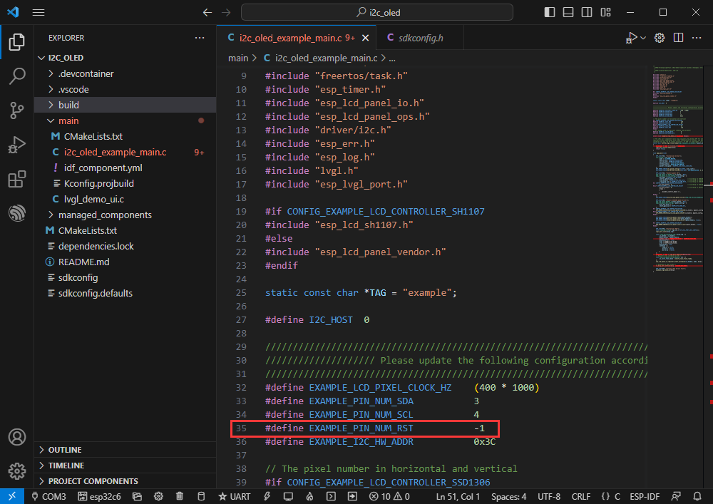
Adapted to 0.96inch OLED (A), define the RES pin as GPIO9

Modify the COM port and driver object, click compile and burn to run the program
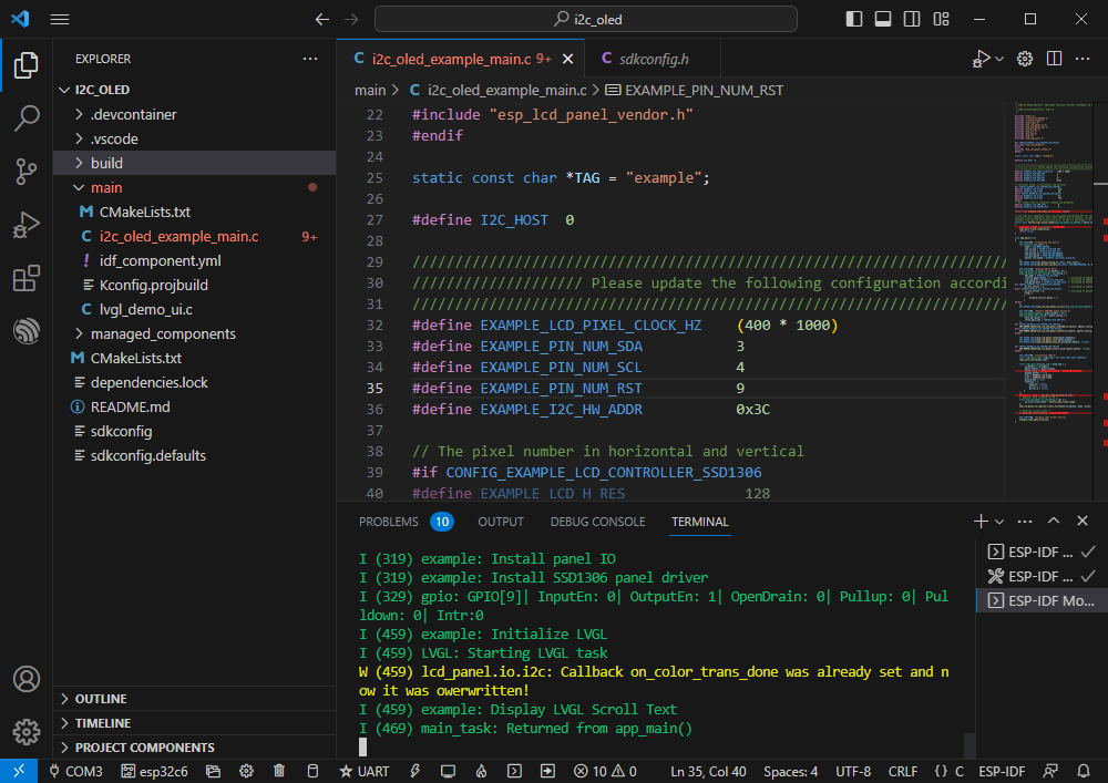
The effect is as follows
You can view the actual GPIO used
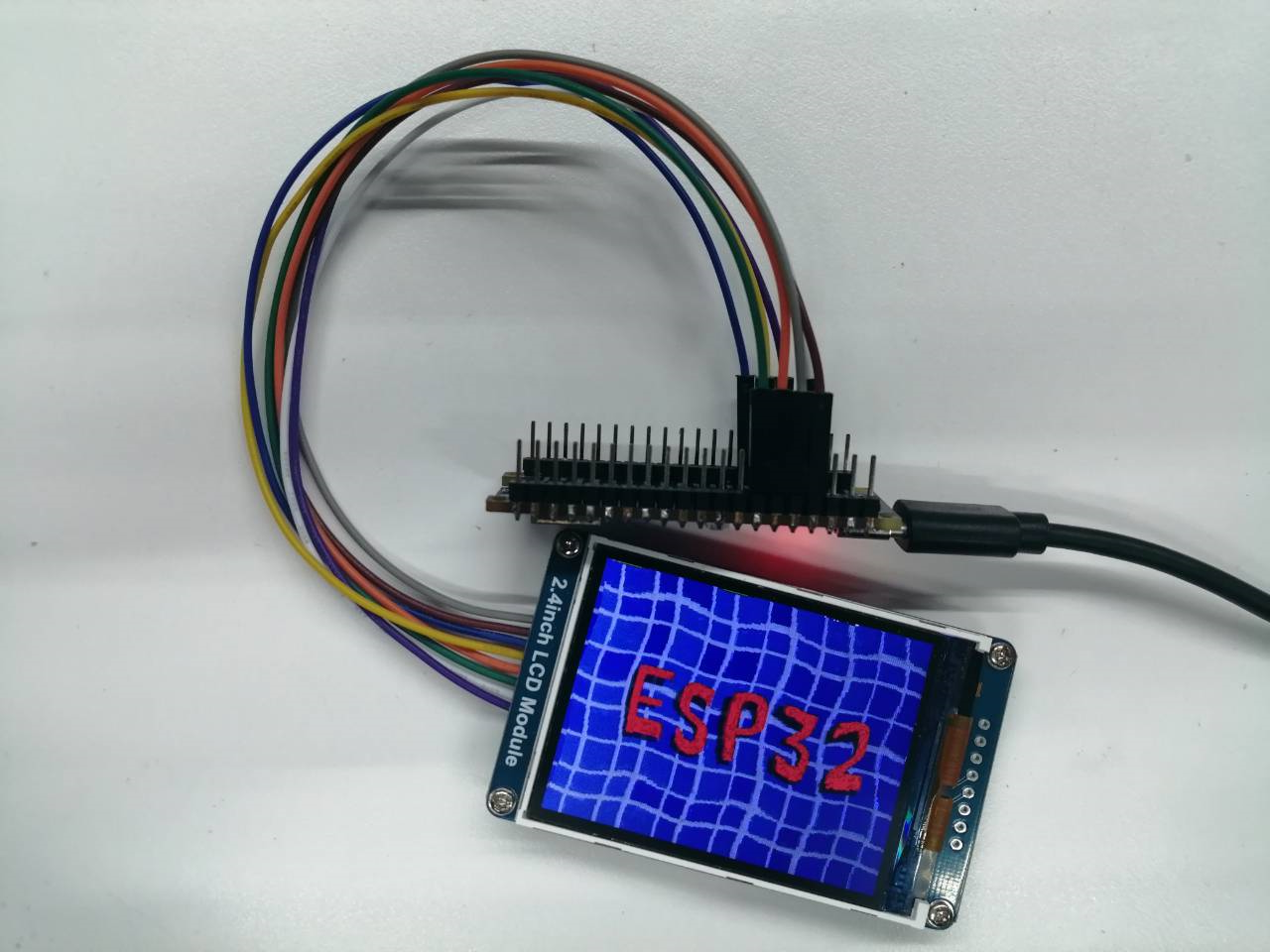
SPI
Official example path: peripherals -> spi_master-> lcd
Example effect: Dynamically display pictures on 2.4inch LCD Module
Hardware connection
| 2.4inch LCD Module | ESP32-C6 |
| VCC | 3V3 |
| GND | GND |
| DIN | GPIO7 |
| CLK | GPIO6 |
| CS | GPIO0 |
| D/C | GPIO1 |
| RES | GPIO4 |
| BL | GPIO5 |
Software operation
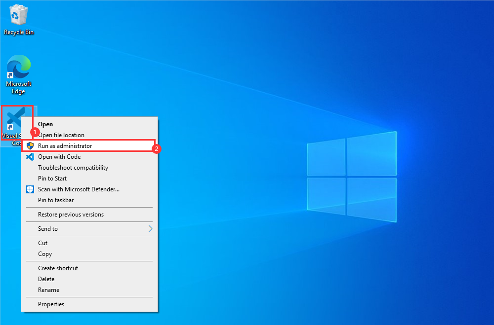
Right-click the VScode icon and run VScode as administrator
Create an official sample LCD according to the tutorial above
Modify the program to make it compatible with 2.4inch LCD Module
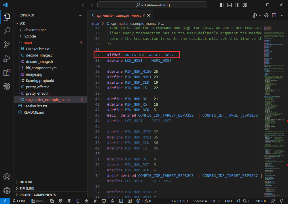
Jump to defined location
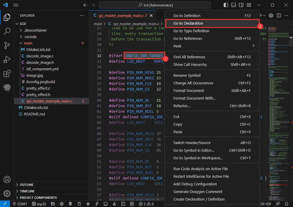
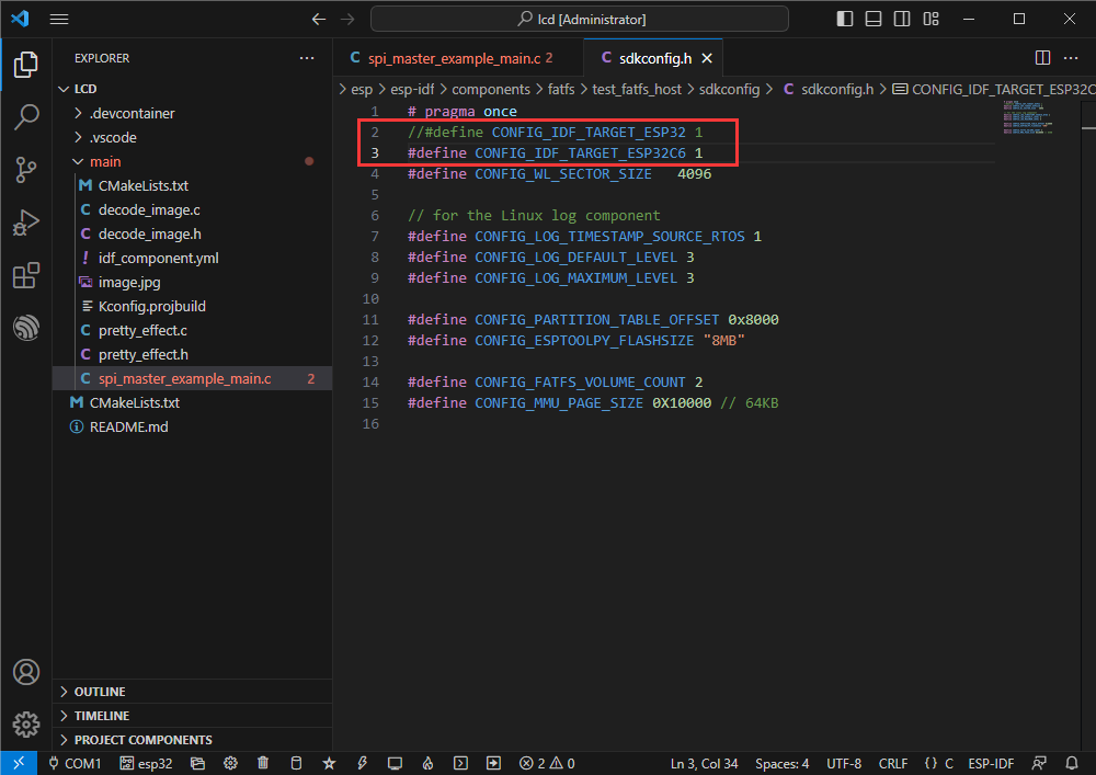
The one currently used is ESP32-C6, and other chip definitions are blocked.
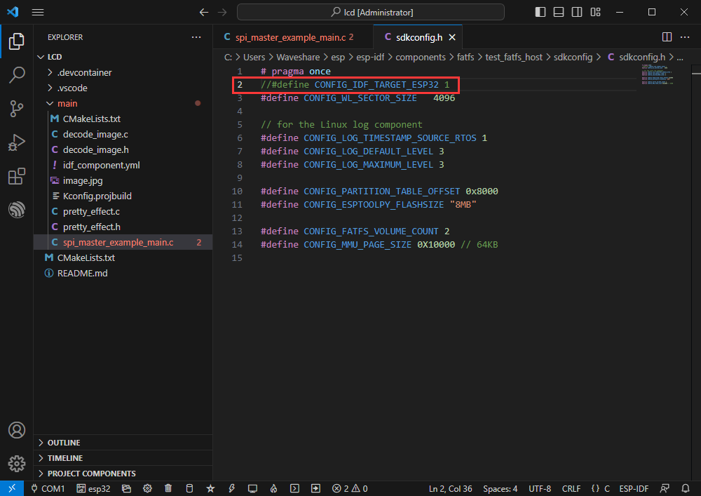
And macro definition ESP32-C6, CONFIG_IDF_TARGET_ESP32C6
//#define CONFIG_IDF_TARGET_ESP32 1
#define CONFIG_IDF_TARGET_ESP32C6 1
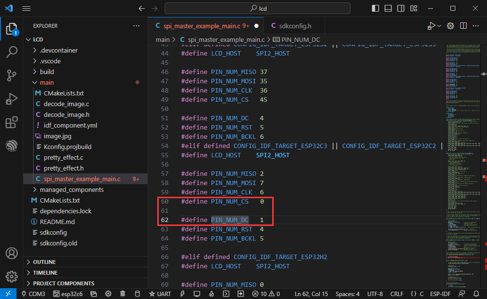
Modify D/C to use IO
- Enter line 60 of spi_master_example_main.c
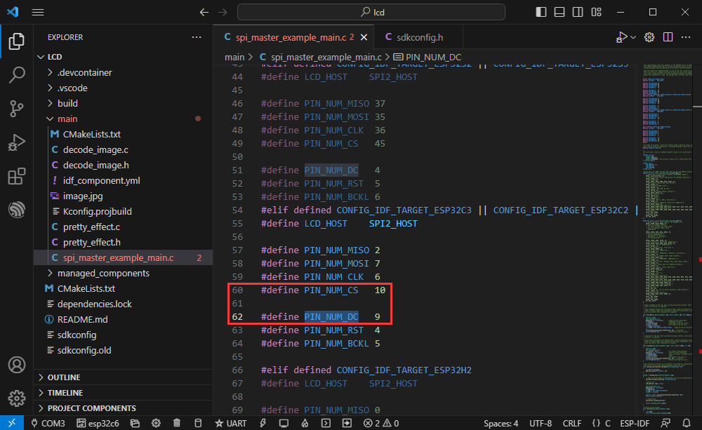
Modify D/C to use IO and select existing IO (the original use of GPIO10 and GPIO9 is changed to GPIO0 and GPIO1)
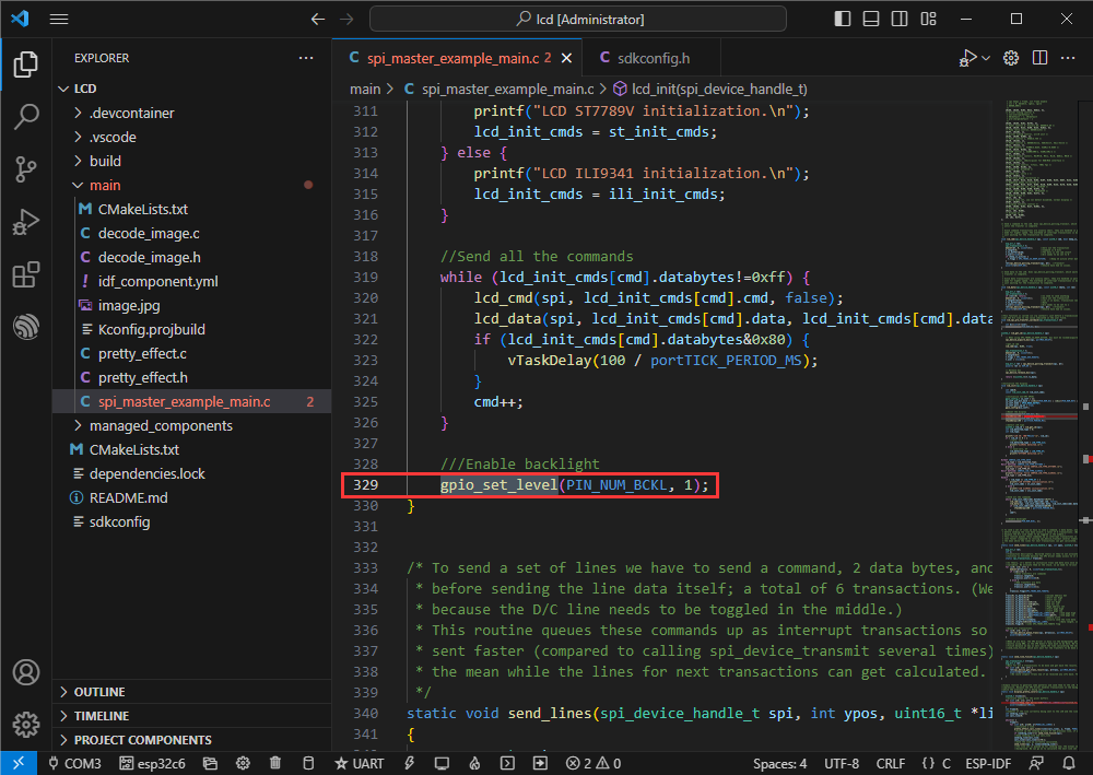
Modify backlight
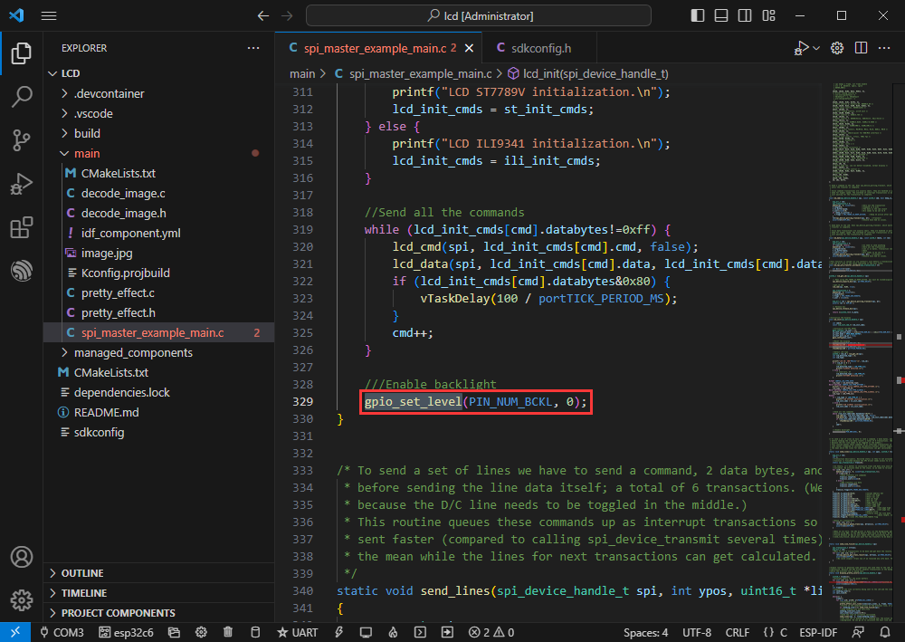
Change to gpio_set_level(PIN_NUM_BCKL, 1) ;
Modify the COM port and driver object, click compile and burn to run the program
The effect is as follows
Bluetooth
[] Official example path: bluetooth -> bluedroid -> ble -> gatt_server
[] Example effect: ESP32-C6 and mobile phone Bluetooth debugging assistant for data transmission
Software operation
Install Bluetooth debugging assistant on mobile phone
Create the official example gatt_server according to the tutorial above
The program is compatible with ESP32-C6 and can be used without modifying the program content.
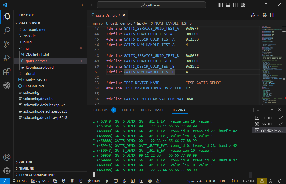
Bluetooth name and UUID, the Bluetooth name is ESP_GATTS_DEMO
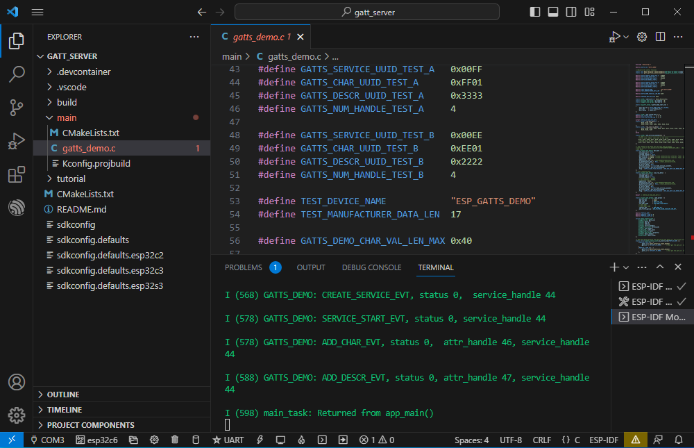
Modify the COM port and driver object, click compile and burn to run the program
Connect the ESP_GATTS_DEMO Bluetooth device on the mobile phone
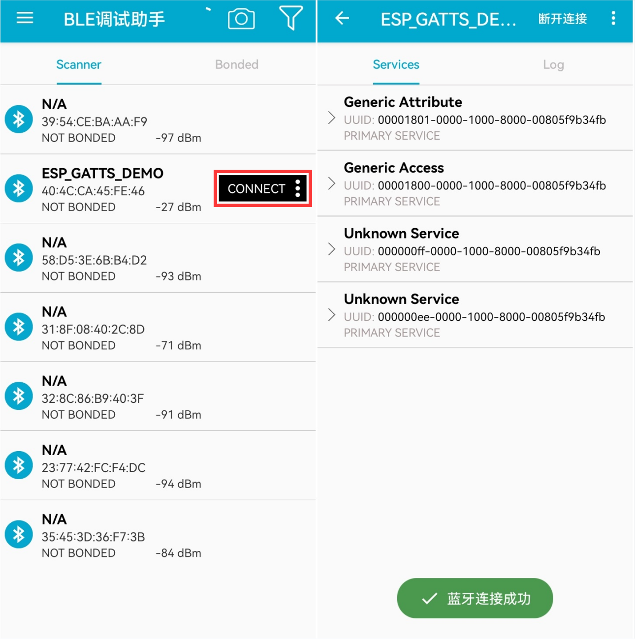
The effect of successful connection is as follows
According to the UUID value in the program, there are two servers below. Select one of them for uplink transmission.
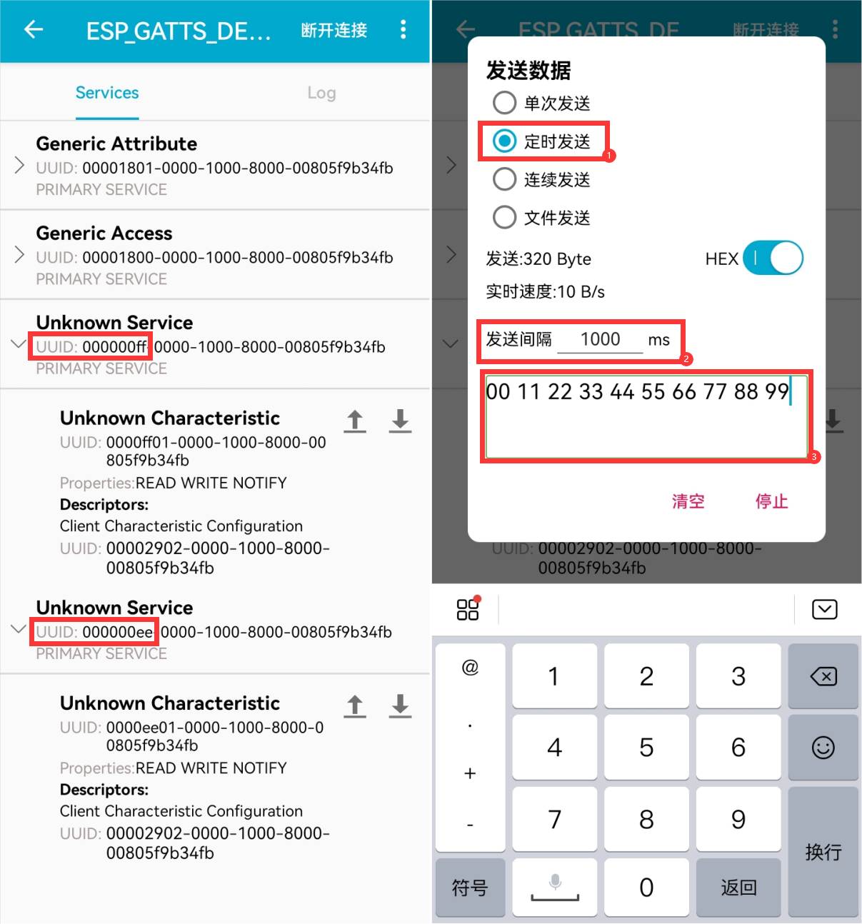
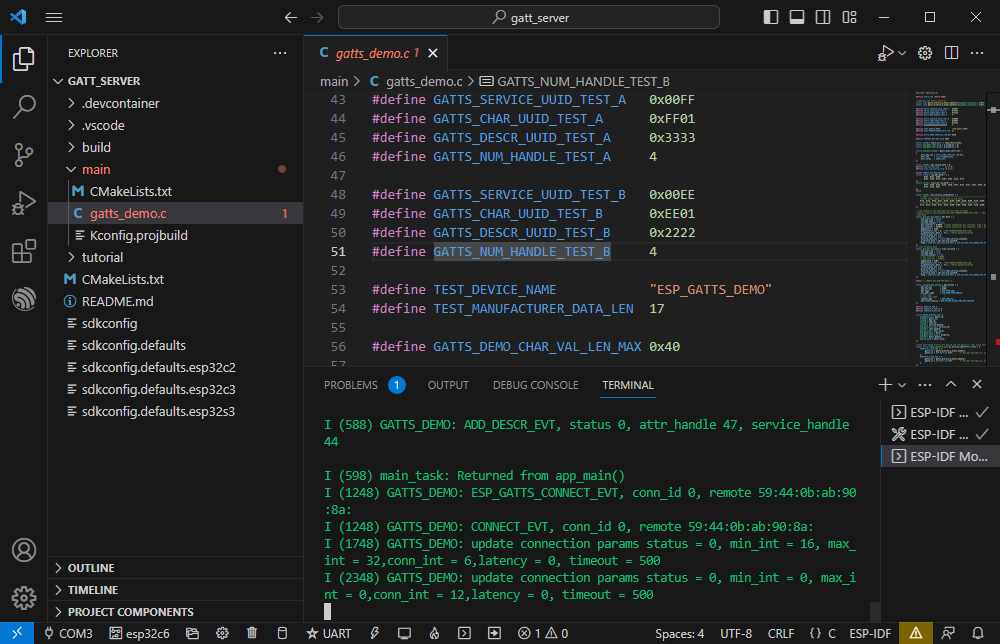
ESP32-C6 receives data
WIFI
[] Official example path: wifi-> getting_started-> station
[] Example effect: ESP32-C6 connected to WIFI
Software operation
Create an official sample station according to the tutorial above
Modify the program content so that it can connect to the required WiFi
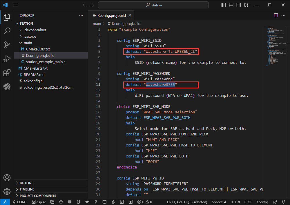
Enter the Kconfig.projbuild file
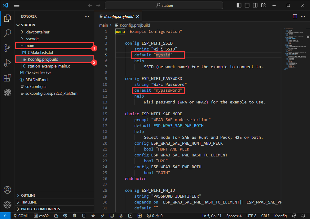
Change the original WiFi SSID and WiFi Password to the WiFi information to be connected
Modify the COM port and driver object, click compile and burn to run the program
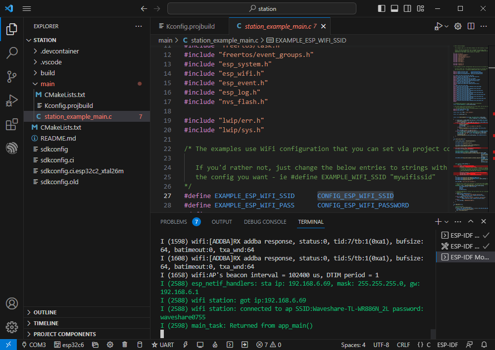
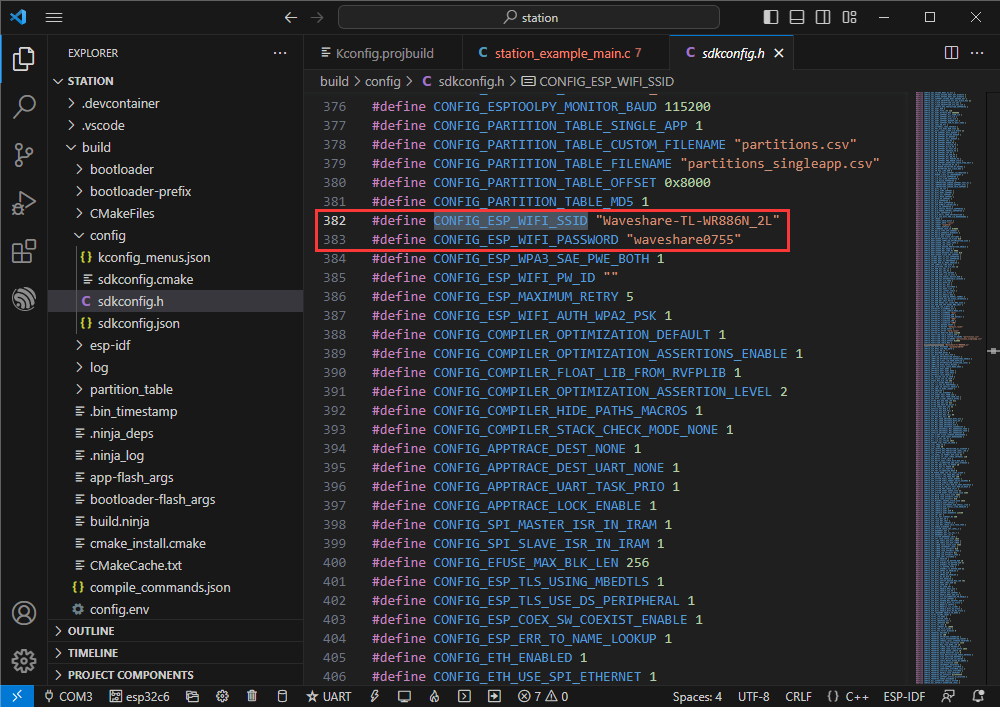
You can view the value of CONFIG_ESP_WIFI_SSID
Enter the station_ example_ main.c file
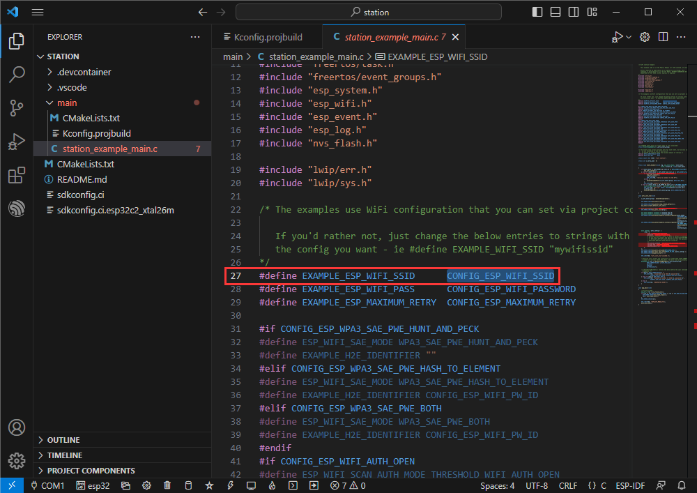
Right click and go to definition
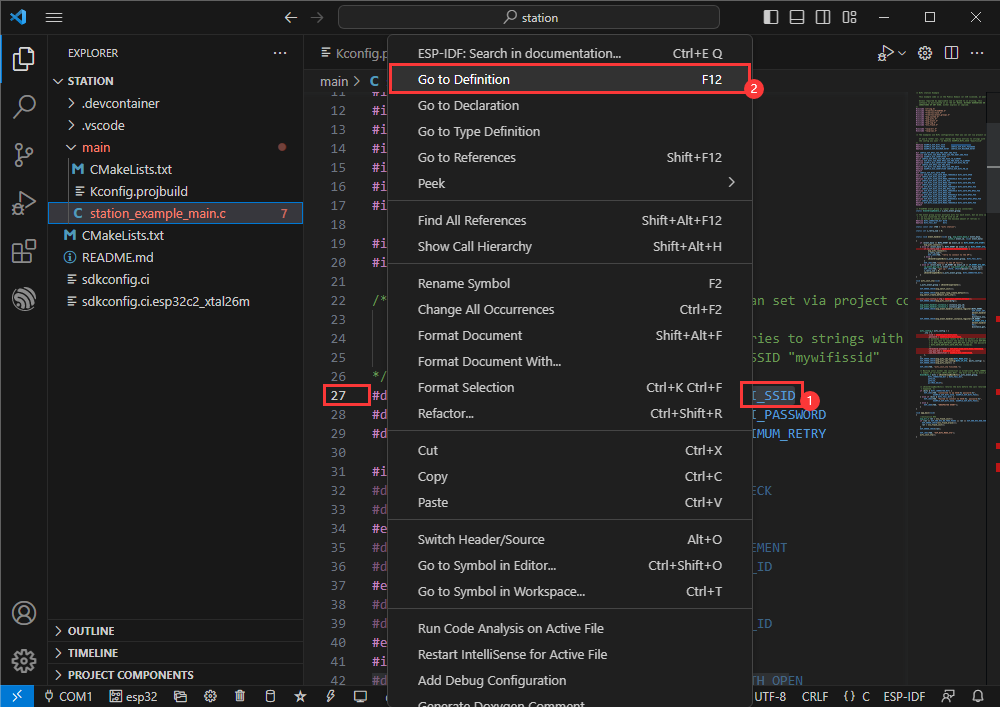
You can see the value you set previously
Zigbee
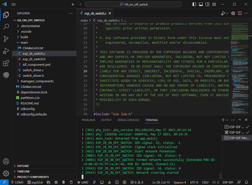
[] Official sample 1 path: Zigbee-> light_sample-> HA_on_off_switch
[] Official sample 2 path: Zigbee-> light_sample-> HA_on_off_light
[] Example effect: Two ESP32-C6s, use the BOOT button of one (burning HA_on_off_switch program) to control the RGB lamp beads of the other one.
Note: Please burn the HA_on_off_switch program to one block first, and then burn the HA_on_off_light program to the other block.
Software operation 1
Create the official example HA_on_off_switch according to the tutorial above
The program is compatible with ESP32-C6 and can be used without modifying the program content.
Modify the COM port and driver object, click compile and burn to run the program
Software operation 2
Create the official example HA_on_off_light according to the tutorial above
The program is compatible with ESP32-C6 and can be used without modifying the program content.
Modify the COM port and driver object, click compile and burn to run the program (you need to wait a moment for the two chips to establish a connection)
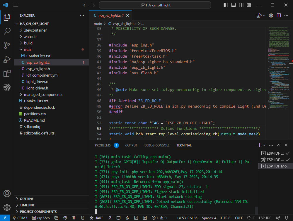
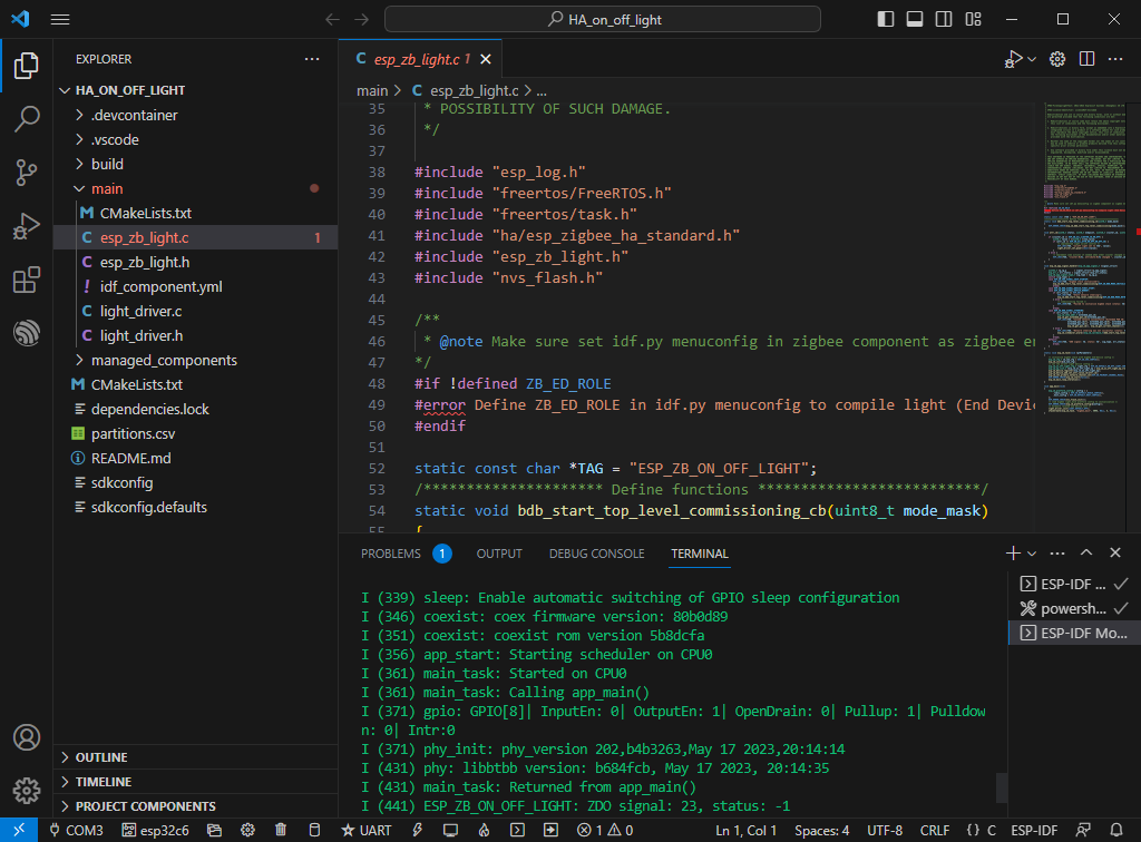
If it remains unconnected as shown below , it may be because the device has residual network information. You can erase the device information and re-establish the network.
JTAG debugging
Software operation
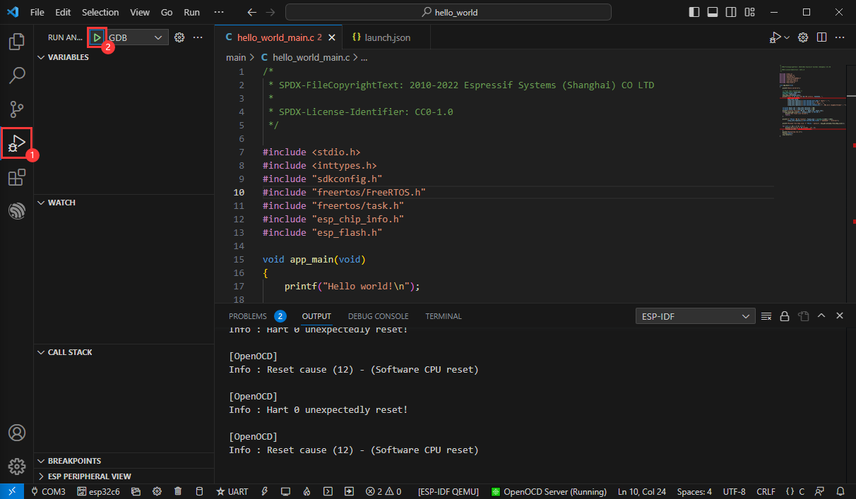
[] Create an example that needs to be debugged. This example uses the official example hello_world
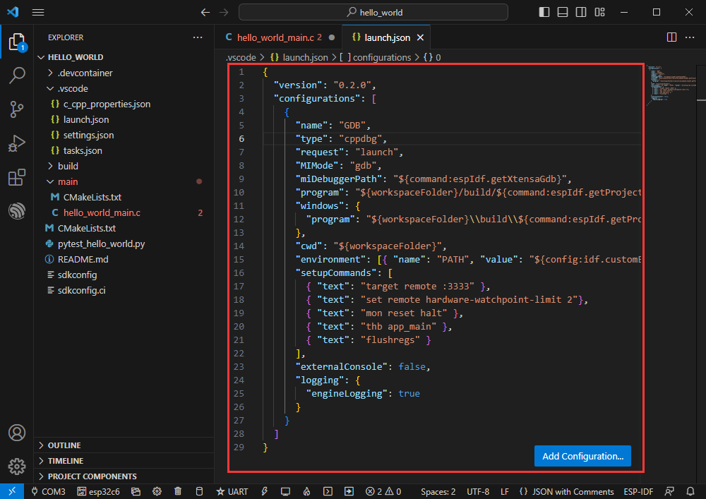
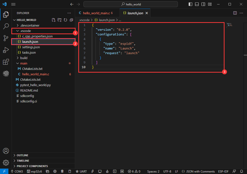
[] Modify launch.json file
Enter the following
{
 "version": "0.2.0",
 "configurations": [
   {
     "name": "GDB",
     "type": "cppdbg",
     "request": "launch",
     "MIMode": "gdb",
     "miDebuggerPath": "${command:espIdf.getXtensaGdb}",
     "program": "${workspaceFolder}/build/${command:espIdf.getProjectName}.elf",
     "windows": {
       "program": "${workspaceFolder}\\build\\${command:espIdf.getProjectName}.elf"
     },
     "cwd": "${workspaceFolder}",
     "environment": [{ "name": "PATH", "value": "${config:idf.customExtraPaths}" }],
     "setupCommands": [
       { "text": "target remote :3333" },
       { "text": "set remote hardware-watchpoint-limit 2"},
       { "text": "mon reset halt" },
       { "text": "thb app_main" },
       { "text": "flushregs" }
     ],
     "externalConsole": false,
     "logging": {
       "engineLogging": true
     }
   }
 ]
}
The program is compatible with ESP32-C6 and can be used without modifying the program content.
Modify the COM port and driver object (please use the USB interface, the UART interface does not support JTAG debugging, the corresponding COM port can be viewed through the device manager) , click compile and burn to run the program
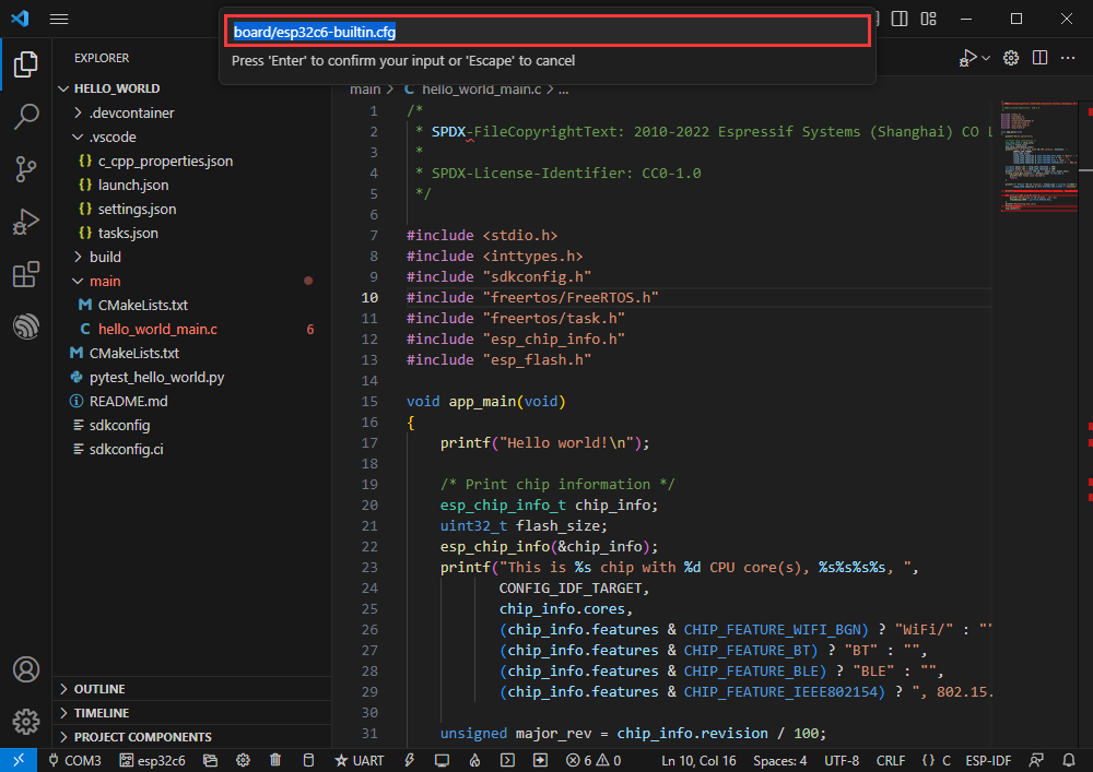
Click the shortcut key F1 and enter
ESP-IDF:Device configuration
Select OpenOcd Config Files
Enter board/esp32c6-builtin.cfg (if the default is this, just press Enter)
board/esp32c6-builtin.cfg
Stretch the window width until [OpenOCD Server] is displayed below
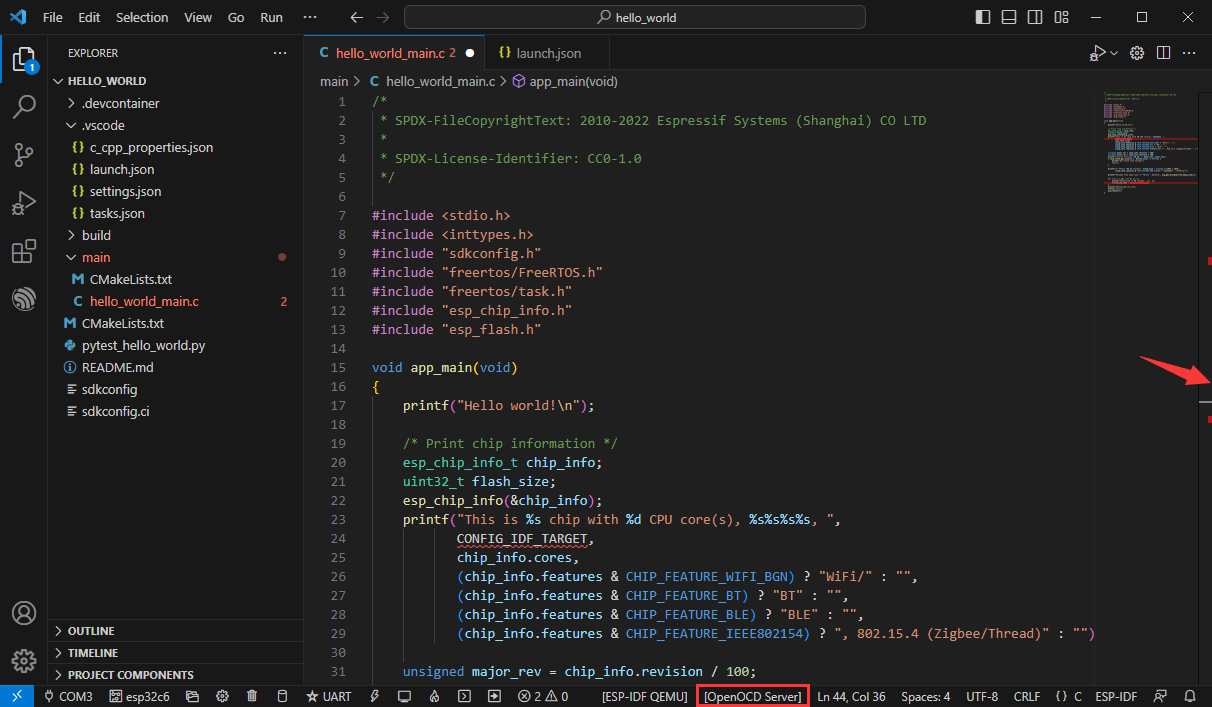
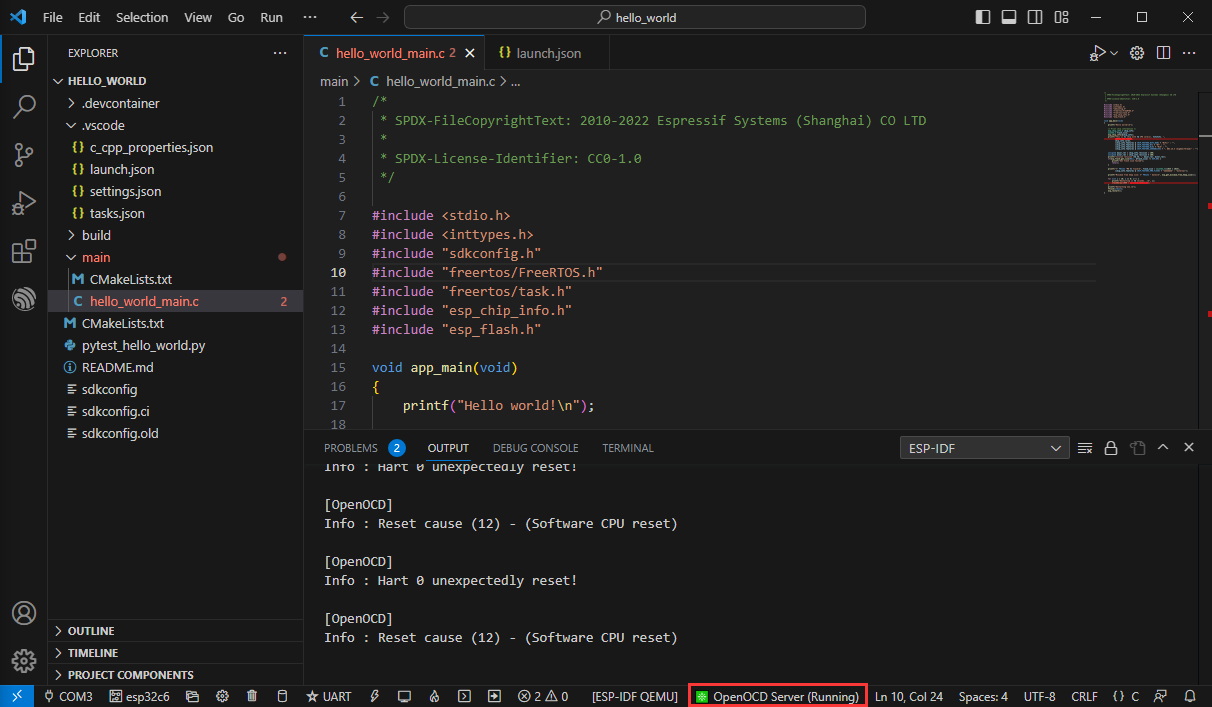
Click [OpenOCD Server] and select Start OpenOCD
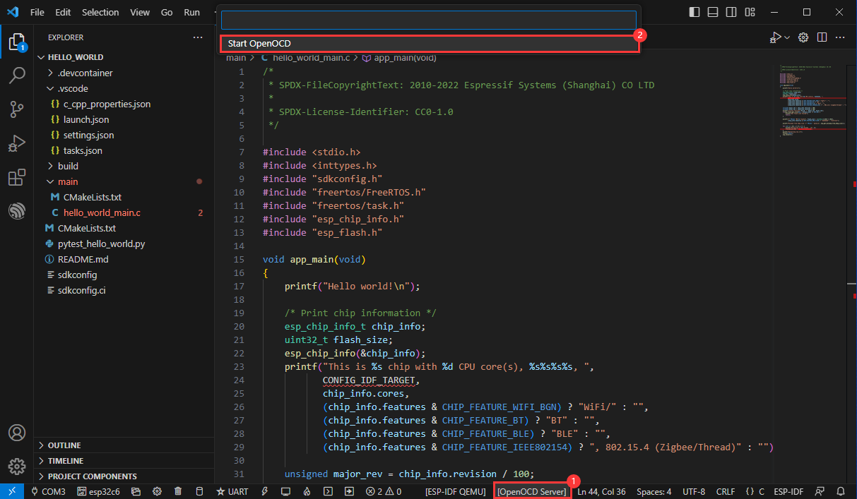
The successful opening is as follows
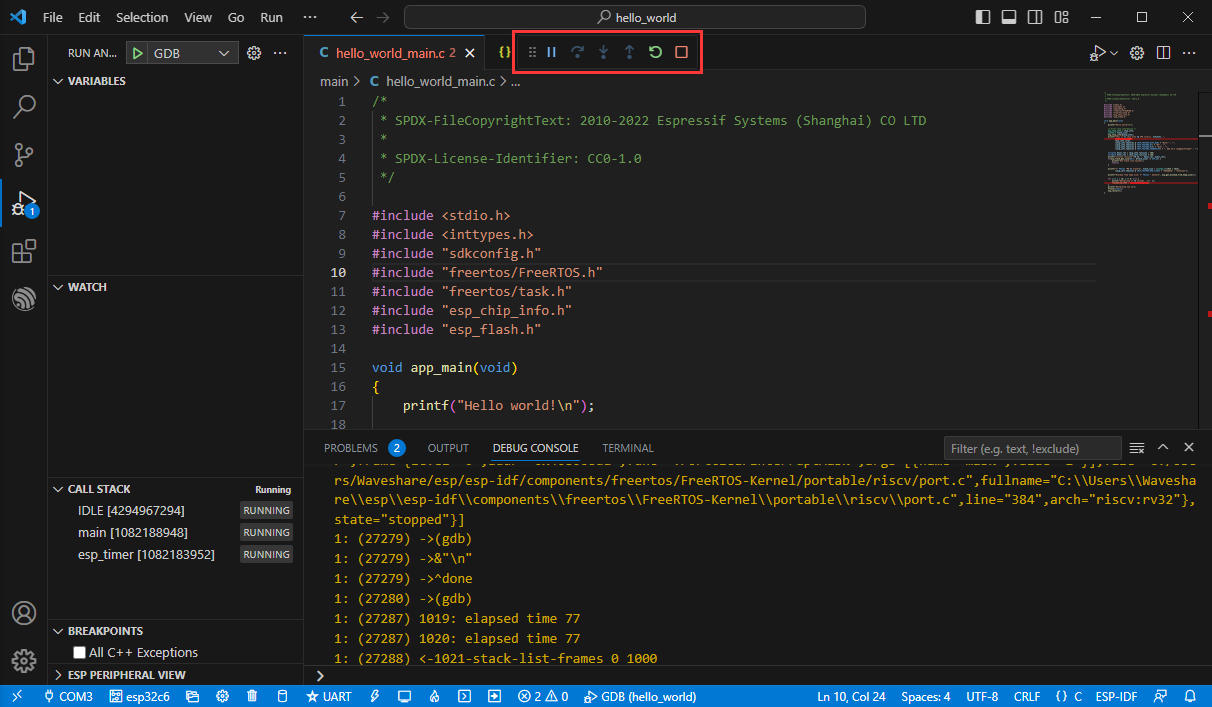
Enter the debugging function and click Debug
Successfully entered the debugging interface
Wipe device Flash
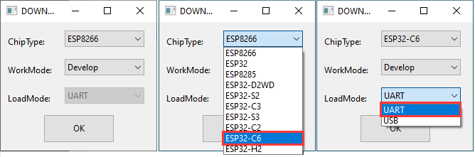
Unzip the software resource package ( Flash debugging software )
Open the flash_download_tool_3.9.5.exe software and select ESP32-C6 and UART
Select the UART port number and click START (do not select any bin file)
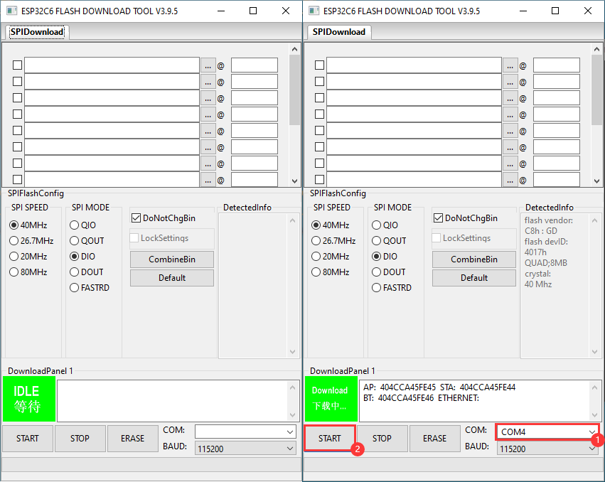
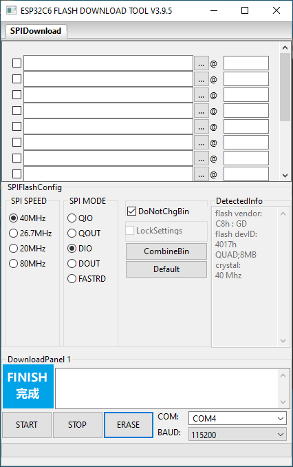
Wait for burning to complete, click Erase
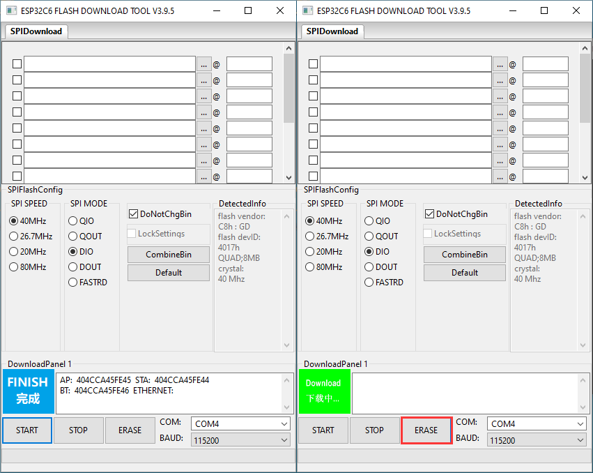
Wait for erasure to complete
[Use under Arduino]
Please note that Arduino 3.0.0-alpha is developed based on ESP-IDF v5.1, which is quite different from the previous ESP-IDF V4.X. After performing the following operations, the original program may require some adjustments before it can be used.
Computer usernames in Chinese will cause compilation errors
【Building environment】
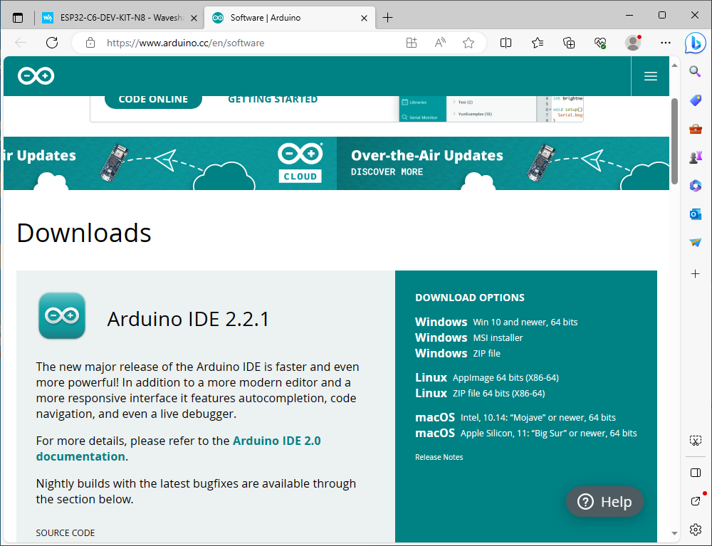
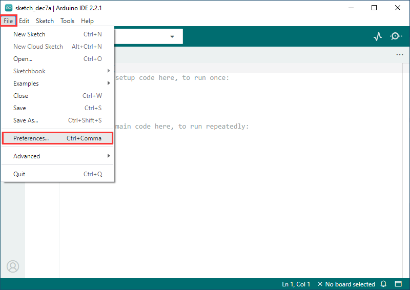
Install Arduino IDE
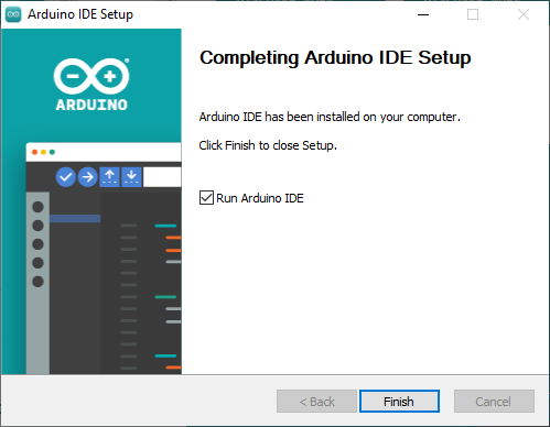
After the installation is complete, open the Arduino IDE
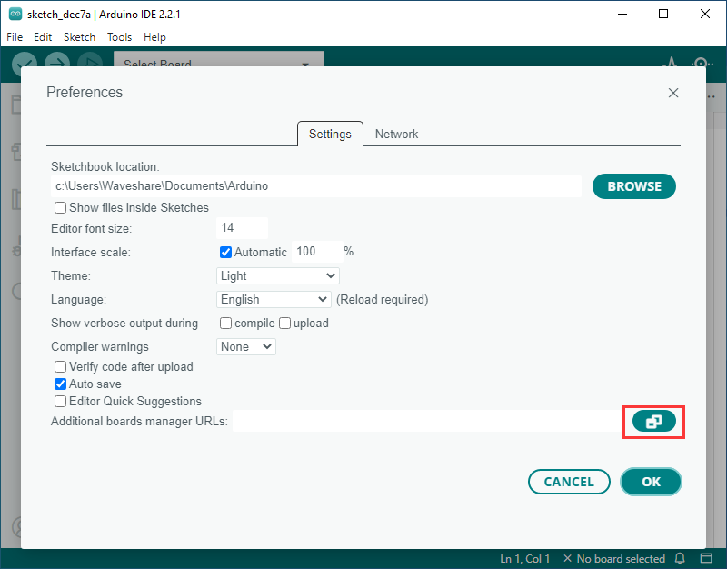
Go to preferences
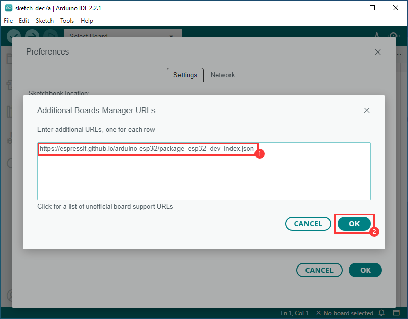
Add JSON link
https://espressif.github.io/arduino-esp32/package_esp32_dev_index.json
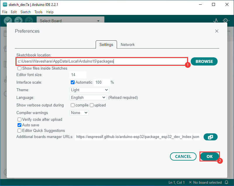
Modify the project folder to C:\Users\Spotpear\AppData\Local\Arduino15\packages (where Spotpear is the computer username)
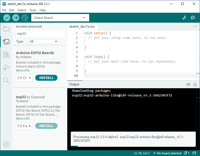
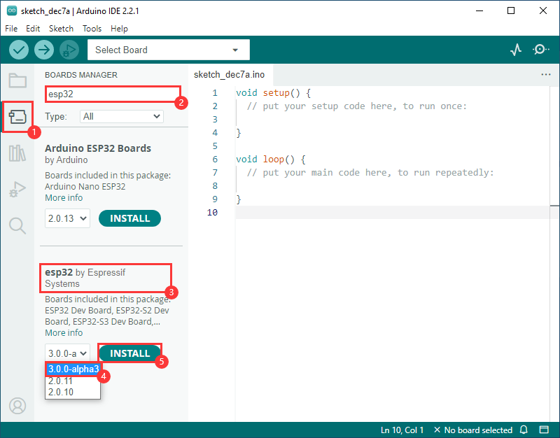
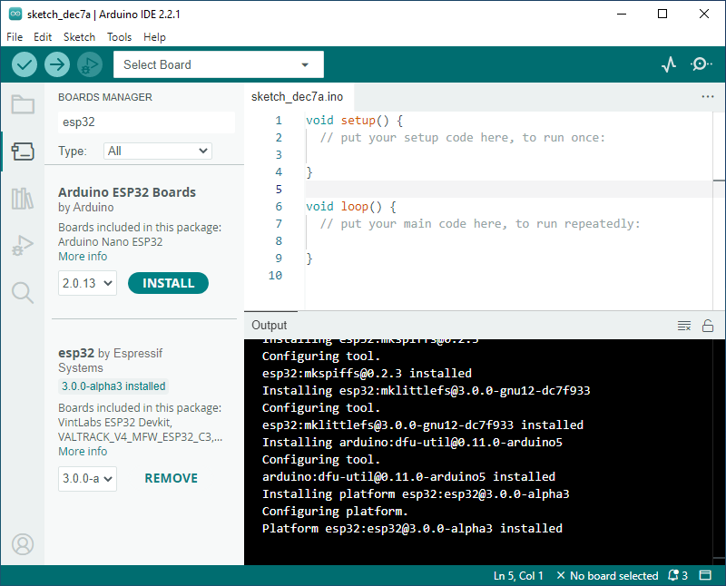
Enter the development board manager, search for esp32, select version 3.0.0-alpha3 in esp32 by Espressif Systems below and click to install (if it cannot be installed normally, you can try using a mobile phone hotspot)

After the installation is complete, restart the Arduino IDE and it will be ready to use.

Expand if installation fails
Installation of version 3.0.0-alpha3 failed
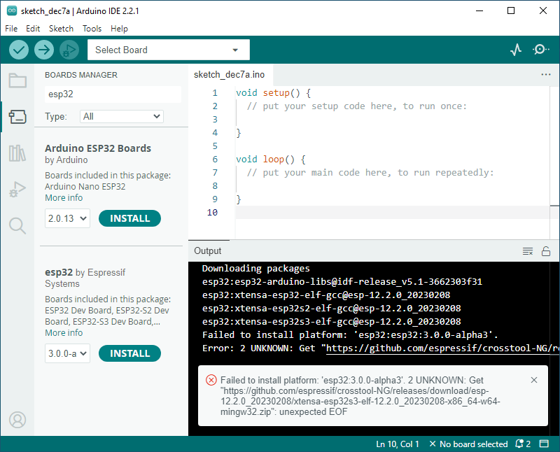
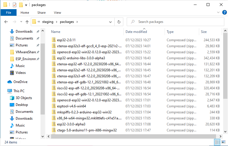
Download resource file
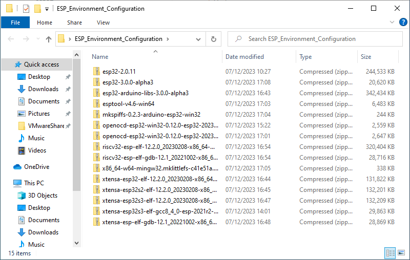
Link: https://pan.baidu.com/s/1u99HFx8lAyNLZzj7ja13lA
Extraction code: 0755
Enter from the resource manager by the path "c:\Users\Spotpear\AppData\Local\Arduino15\packages" (where Spotpear is the computer username, you need to turn on the display of hidden files)
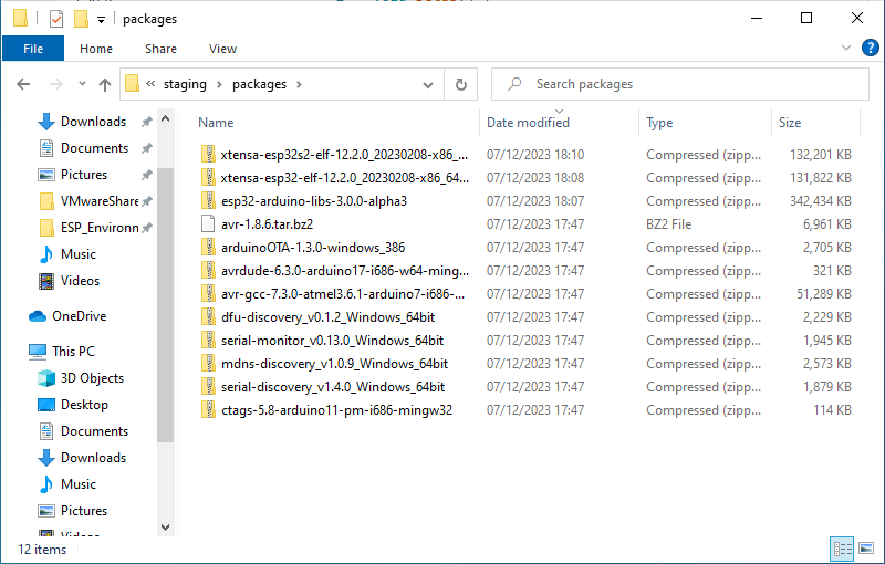
Unzip the file downloaded above into the packages folder
Re-execute the installation operation
After the installation is complete, restart the Arduino IDE and it will be ready to use.
Create an example
[] After changing the project folder above to c:\Users\Spotpear\AppData\Local\Arduino15\packages (where Spotpear is the computer user name)
[] Routines can be created from examples in the project folder under Files
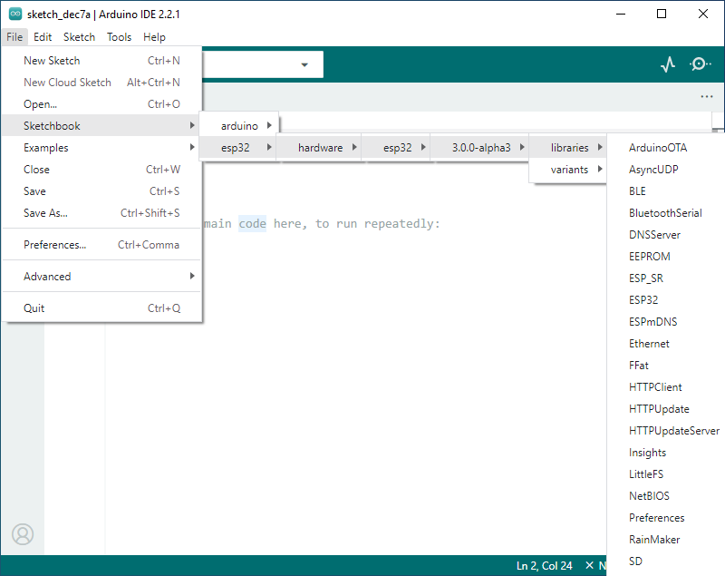
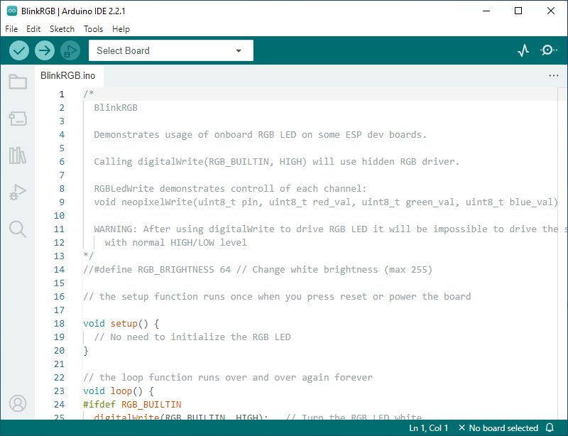
The following demo creates an example of RGB blinking (BlinkRGB under File -> Sketchbook -> esp32 -> hardware -> esp32 -> 3.0.0-alpha3 -> libraries -> ESP32 -> examples -> GPIO )
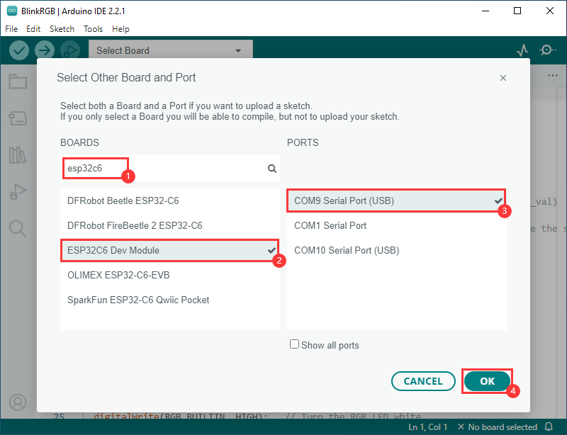
Select development board and port
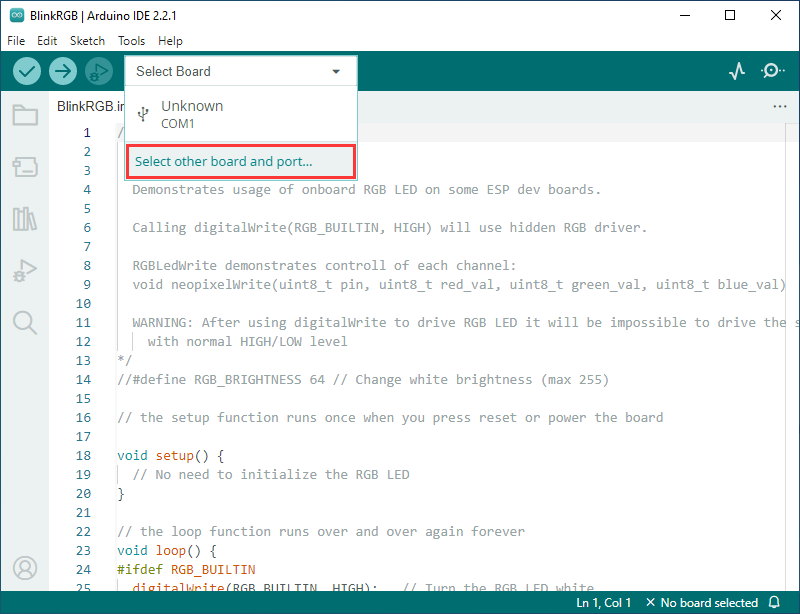
Search esp32c6 , select ESP32C6 Dev Module and download port
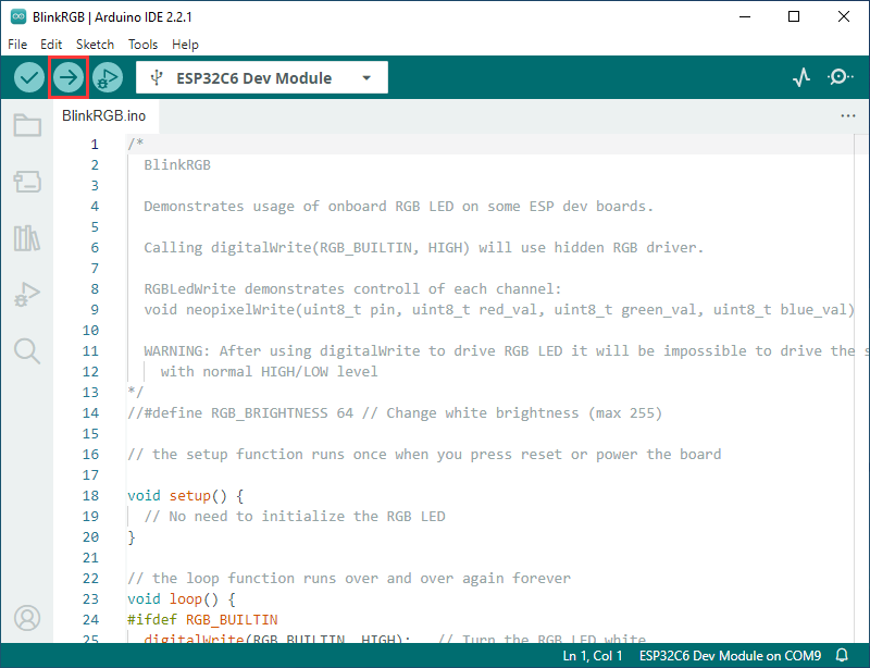
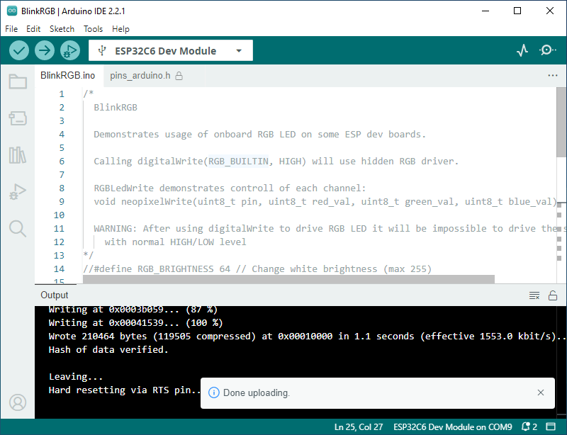
Select Finish, click Upload, Arduino IDE will compile and burn the program
After the upload is completed, you can see the phenomenon on the development board
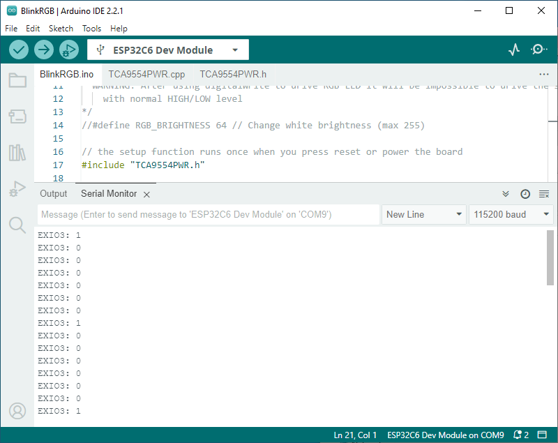
Add EXIO control program under Arduino IDE
[] Use the official example BlinkRGB to demonstrate the modification steps
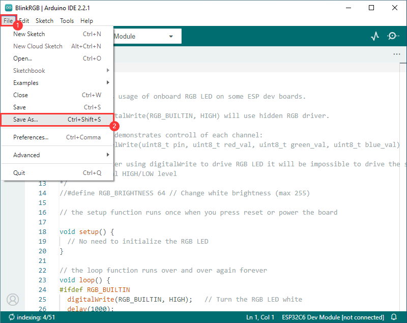
[] Create the official sample BlinkRGB according to the tutorial above
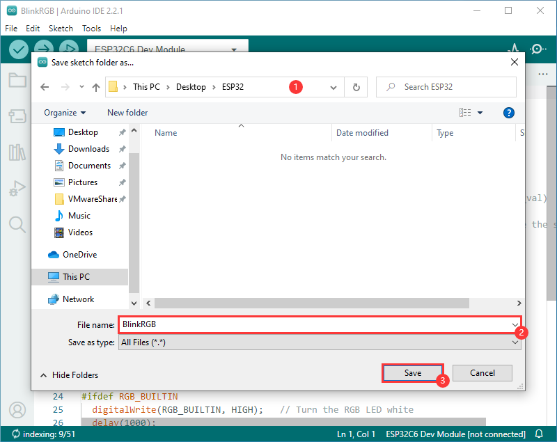
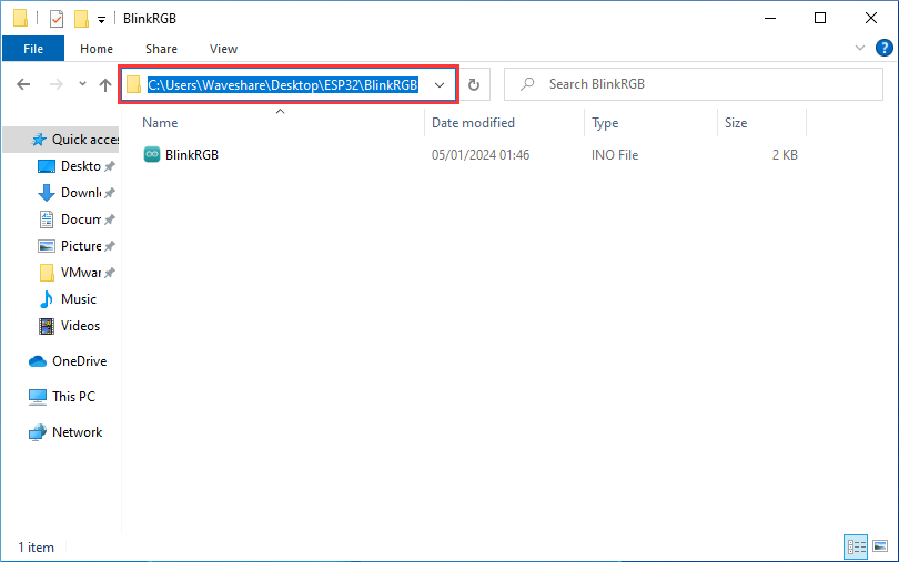
[] For convenience, save it to another path
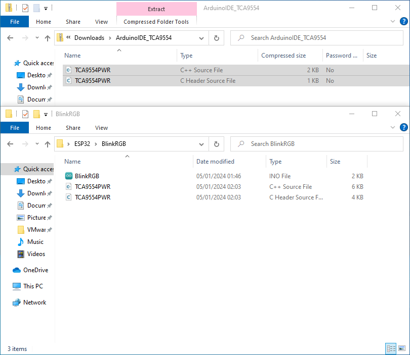
Download EXIO control program
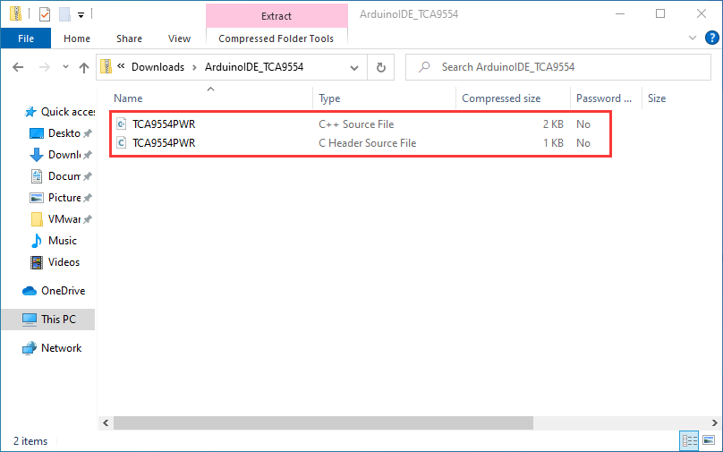
Enter the directory you just saved and copy the EXIO control program to the project folder of BlinkRGB
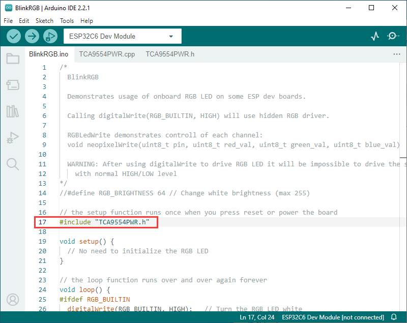
Reference the TCA9554PWR file in BlinkRGB.ino
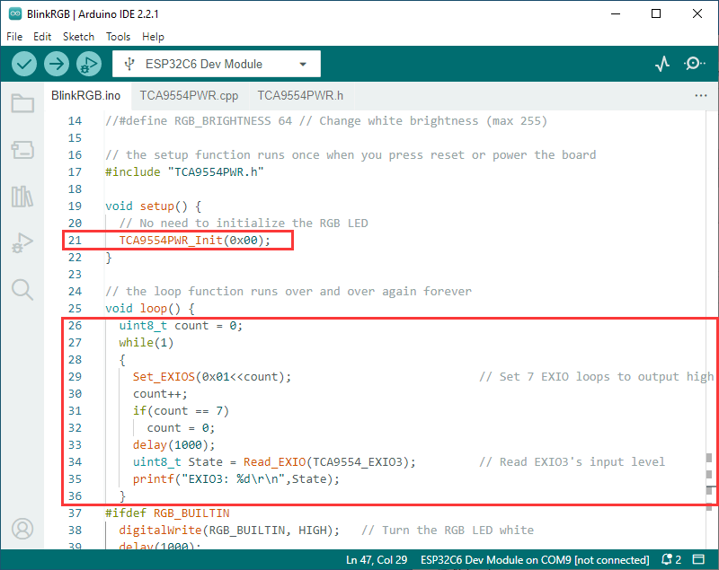
Currently, EXIO1 ~ EXIO7 can be operated through the EXIO control function.
As shown below, add the following code in setup() and loop() to realize that EXIO1 to EXIO7 output high level in sequence, and print the level status of EXIO3 in real time.
TCA9554PWR_Init(0x00);
uint8_t count = 0;
while(1)
{
  Set_EXIOS(0x01<<count); // Set 7 EXIO loops to output high levels
  count++;
  if(count == 7)
    count = 0;
  delay(1000);
  uint8_t State = Read_EXIO(TCA9554_EXIO3); // Read EXIO3's input level
  printf("EXIO3: %d\r\n",State);
} 
The operation effect is as follows