- sales/support
Google Chat: zj734465502@gmail.com
- sales
+86-0755-88291180
- sales01
sales01@spotpear.com
- sales02
dragon_manager@163.com
- support
services01@spotpear.com
- CEO-Complaints
manager01@spotpear.com
- sales/support
WhatsApp:13246739196
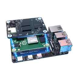
CB1 User Guide
The BIGTREETECH CB1 is launched to provide a great solution to the insane shortage of Raspberry Pi CM4. It outputs signals to the motherboard via the fast and convenient two 100 pins micro BTB connection header, including 100M Ethernet, HDMI, etc. Also, onboard 2.4G WiFi.
1.1 Feature Highlights
1. CPU: ALLWINNER H616, Quad-core Cortex-A53 @1.5GHz
2. GPU: Mali G31 MP2, Support OpenGL3.2
3. RAM: 512MB/1GB DDR3L SDRAM
4. Display: Compatible with HDMI2.0A Interface, Support 4K Displays
5. Compatible with USB2.0 Interface
6. Support 100M Ethernet + 100M WiFi
7. Having the same BTB header as the Raspberry Pi CM4.
1.2 Specifications
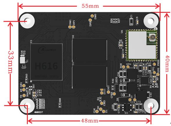
1. Product Size: 40mm x 55mm
2. Mounting Size: 33mm x 48mm
3. Input Voltage: 5V±5%/2A
4. Output Voltage: 3.3V±2%/100mA
5. Output Voltage: 1.8V±2%/100mA
6. WiFi: 2.4G/802.11 b/g/n
1.3 Dimensions
二. Peripheral Port
2.1 Pin | |||
|
|
| |
PIN | Connector | Signal | Description |
1 | A connector_01 | GND | |
2 | A connector_02 | GND | |
3 | A connector_03 | NC | |
4 | A connector_04 | EPHY-TXP | Ethernet TX Positive |
5 | A connector_05 | NC | |
6 | A connector_06 | EPHY-TXN | Ethernet TX Negative |
7 | A connector_07 | GND | |
8 | A connector_08 | GND | |
9 | A connector_09 | NC | |
10 | A connector_10 | EPHY-RXP | Ethernet RX Positive |
11 | A connector_11 | NC | |
12 | A connector_12 | EPHY-RXN | Ethernet RX Negative |
13 | A connector_13 | GND | |
14 | A connector_14 | GND | |
15 | A connector_15 | LINK_LED | Ethernet LED |
16 | A connector_16 | NC | |
17 | A connector_17 | SPD_LED | Ethernet LED |
18 | A connector_18 | NC | |
19 | A connector_19 | NC | |
20 | A connector_20 | NC | |
21 | A connector_21 | SYS-LED | System work light |
22 | A connector_22 | GND | |
23 | A connector_23 | GND | |
24 | A connector_24 | PC15 | 3.3V IO(CB1 V2.1 is 1.8v ) |
25 | A connector_25 | PC8 | 3.3V IO(CB1 V2.1 is 1.8v ) |
26 | A connector_26 | PC6 | 3.3V IO(CB1 V2.1 is 1.8v ) |
27 | A connector_27 | PH10 | 3.3V IO |
28 | A connector_28 | NC | |
29 | A connector_29 | NC | |
30 | A connector_30 | PG6 | 3.3V IO |
31 | A connector_31 | PG9 | 3.3V IO |
32 | A connector_32 | GND | |
33 | A connector_33 | GND | |
34 | A connector_34 | NC | |
35 | A connector_35 | PG7 | 3.3V IO |
36 | A connector_36 | NC | |
37 | A connector_37 | PG8 | 3.3V IO |
38 | A connector_38 | PH6 | 3.3V IO |
39 | A connector_39 | NC | 3.3V IO |
40 | A connector_40 | PH8 | 3.3V IO |
41 | A connector_41 | NC | |
42 | A connector_42 | GND | |
43 | A connector_43 | GND | |
44 | A connector_44 | PH7 | 3.3V IO |
45 | A connector_45 | PC9 | 3.3V IO(CB1 V2.1 is 1.8v ) |
46 | A connector_46 | PC10 | 3.3V IO(CB1 V2.1 is 1.8v ) |
47 | A connector_47 | PC11 | 3.3V IO(CB1 V2.1 is 1.8v ) |
48 | A connector_48 | PC12 | 3.3V IO(CB1 V2.1 is 1.8v ) |
49 | A connector_49 | PC13 | 3.3V IO(CB1 V2.1 is 1.8v ) |
50 | A connector_50 | PC14 | 3.3V IO(CB1 V2.1 is 1.8v ) |
51 | A connector_51 | SoC_RX | DEBUG UART |
52 | A connector_52 | GND | |
53 | A connector_53 | GND | |
54 | A connector_54 | PC7 | 3.3V IO(CB1 V2.1 is 1.8v ) |
55 | A connector_55 | SoC_TX | DEBUG UART |
56 | A connector_56 | NC | |
57 | A connector_57 | SDC0-CLK | SDCARD Clock signal |
58 | A connector_58 | NC | |
59 | A connector_59 | GND | |
60 | A connector_60 | GND | |
61 | A connector_61 | SDC0-D3 | SDCARD Data3 signal |
62 | A connector_62 | SDC0-CMD | SDCARD CMD signal |
63 | A connector_63 | SDC0-D0 | SDCARD Data0 signal |
64 | A connector_64 | PG11 | 3.3V IO |
65 | A connector_65 | GND | |
66 | A connector_66 | GND | |
67 | A connector_67 | SDC0-D1 | SDCARD Data1 signal |
68 | A connector_68 | PG12 | 3.3V IO |
69 | A connector_69 | SDC0-D2 | SDCARD Data2 signal |
70 | A connector_70 | PG13 | 3.3V IO |
71 | A connector_71 | GND | |
72 | A connector_72 | PG14 | 3.3V IO |
73 | A connector_73 | PG16 | 3.3V IO |
74 | A connector_74 | GND | |
75 | A connector_75 | NC | |
76 | A connector_76 | SDC0-DET | SDCARD detect |
77 | A connector_77 | VCC_5V | 5V IN /2A |
78 | A connector_78 | NC | |
79 | A connector_79 | VCC_5V | 5V IN /2A |
80 | A connector_80 | NC | |
81 | A connector_81 | VCC_5V | 5V IN /2A |
82 | A connector_82 | NC | |
83 | A connector_83 | VCC_5V | 5V IN /2A |
84 | A connector_84 | 3V3 | 3.3V out /200mA |
85 | A connector_85 | VCC_5V | 5V IN /2A |
86 | A connector_86 | 3V3 | 3.3V out /200mA |
87 | A connector_87 | VCC_5V | 5V IN /2A |
88 | A connector_88 | 1V8 | 1.8V out /100mA |
89 | A connector_89 | NC | |
90 | A connector_90 | 1V8 | 1.8V out /100mA |
91 | A connector_91 | NC | |
92 | A connector_92 | PWRON | Power switch (useless) |
93 | A connector_93 | FEL | (useless) |
94 | A connector_94 | NC | |
95 | A connector_95 | NC | |
96 | A connector_96 | NC | |
97 | A connector_97 | NC | |
98 | A connector_98 | GND | |
99 | A connector_99 | RECOVERY | Program download (useless) |
100 | A connector_100 | AP-RESET | power reset (useless) |
101 | B connector_1 | NC | |
102 | B connector_2 | NC | |
103 | B connector_3 | USB1-DM | HOST USB1 |
104 | B connector_4 | LINEOUTL | |
105 | B connector_5 | USB1-DP | HOST USB1 |
106 | B connector_6 | LINEOUTR | |
107 | B connector_7 | GND | |
108 | B connector_8 | GND | |
109 | B connector_9 | NC | |
110 | B connector_10 | NC | |
111 | B connector_11 | TV_OUT | CVBS OUT |
112 | B connector_12 | NC | |
113 | B connector_13 | GND | |
114 | B connector_14 | GND | |
115 | B connector_15 | NC | |
116 | B connector_16 | NC | |
117 | B connector_17 | NC | |
118 | B connector_18 | NC | |
119 | B connector_19 | GND | |
120 | B connector_20 | GND | |
121 | B connector_21 | NC | |
122 | B connector_22 | NC | |
123 | B connector_23 | NC | |
124 | B connector_24 | NC | |
125 | B connector_25 | GND | |
126 | B connector_26 | GND | |
127 | B connector_27 | NC | |
128 | B connector_28 | USB3-DM | HOST USB3 |
129 | B connector_29 | NC | |
130 | B connector_30 | USB3-DP | HOST USB3 |
131 | B connector_31 | GND | |
132 | B connector_32 | GND | |
133 | B connector_33 | NC | |
134 | B connector_34 | USB2-DM | HOST USB2 |
135 | B connector_35 | NC | |
136 | B connector_36 | USB2-DP | HOST USB2 |
137 | B connector_37 | GND | |
138 | B connector_38 | GND | |
139 | B connector_39 | NC | |
140 | B connector_40 | USB0-DM | OTG USB |
141 | B connector_41 | NC | |
142 | B connector_42 | USB0-DP | OTG USB |
143 | B connector_43 | NC | |
144 | B connector_44 | GND | |
145 | B connector_45 | NC | |
146 | B connector_46 | NC | |
147 | B connector_47 | NC | |
148 | B connector_48 | NC | |
149 | B connector_49 | NC | |
150 | B connector_50 | GND | |
151 | B connector_51 | HCEC | HDMI CEC |
152 | B connector_52 | NC | |
153 | B connector_53 | HHPD | HDMI Hotplug |
154 | B connector_54 | NC | |
155 | B connector_55 | GND | |
156 | B connector_56 | GND | |
157 | B connector_57 | NC | |
158 | B connector_58 | NC | |
159 | B connector_59 | NC | |
160 | B connector_60 | NC | |
161 | B connector_61 | GND | |
162 | B connector_62 | GND | |
163 | B connector_63 | NC | |
164 | B connector_64 | NC | |
165 | B connector_65 | NC | |
166 | B connector_66 | NC | |
167 | B connector_67 | GND | |
168 | B connector_68 | GND | |
169 | B connector_69 | NC | |
170 | B connector_70 | HTX2P | HDMI TX2 Positive. |
171 | B connector_71 | NC | |
172 | B connector_72 | HTX2N | HDMI TX2 Negative. |
173 | B connector_73 | GND | |
174 | B connector_74 | GND | |
175 | B connector_75 | NC | |
176 | B connector_76 | HTX1P | HDMI TX1 Positive. |
177 | B connector_77 | NC | |
178 | B connector_78 | HTX1N | HDMI TX1 Negative. |
179 | B connector_79 | GND | |
180 | B connector_80 | GND | |
181 | B connector_81 | NC | |
182 | B connector_82 | HTX0P | HDMI TX0 Positive. |
183 | B connector_83 | NC | |
184 | B connector_84 | HTX0N | HDMI TX0 Negative. |
185 | B connector_85 | GND | |
186 | B connector_86 | GND | |
187 | B connector_87 | NC | |
188 | B connector_88 | HTXCP | HDMI CLK Positive. |
189 | B connector_89 | NC | |
190 | B connector_90 | HTXCN | HDMI CLK Negative. |
191 | B connector_91 | GND | |
192 | B connector_92 | GND | |
193 | B connector_93 | NC | |
194 | B connector_94 | NC | |
195 | B connector_95 | NC | |
196 | B connector_96 | NC | |
197 | B connector_97 | GND | |
198 | B connector_98 | GND | |
199 | B connector_99 | HSDA | HDMI I2C |
200 | B connector_100 | HSCL | HDMI I2C |
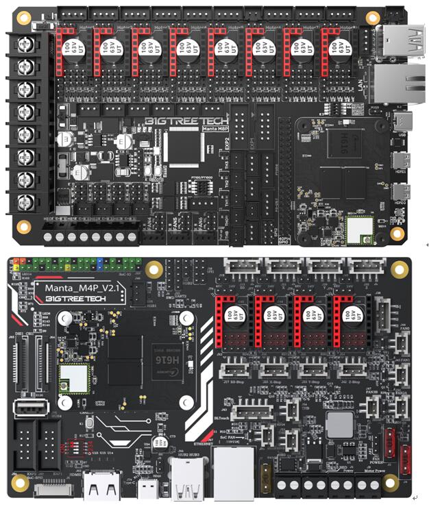
三. Interface Introduction
Install via the BTB Connection
3.2 40 Pins GPIO
When Manta series motherboard work with CB1, 40 pins GPIO is a custom IO arrangement, as shown in the figure below, Pin 7 is CB1's "PC7", and Pin 11 is CB1's "PC14". The GPIO number of CB1 corresponds to (Px–PA)*32 + Pin
For example:
PC7 = (PC–PA)*32 + 7 = 2 * 32 + 7 = 71
PH10 = (PH–PA)*32 + 10 = 7 * 32 + 10 = 234
PC7 is numbered in Klipper as pin: host: gpio71, PH10 as pin: host: gpio234
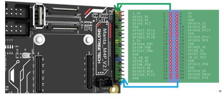
Note: The logic voltage of PC ports in V2.1 version (PC6, PC7, PC8, PC9, PC10, PC11, PC12, PC13, PC14, PC15): 1.8V;
The logic voltage of PC ports in V2.2 version (PC6, PC7, PC8, PC9, PC10, PC11, PC12, PC13, PC14, PC15): 3.3V.
四. Write OS
4.1 Download the OS Image
Please download and install the OS image we provided: https://github.com/bigtreetech/CB1/releases
4.2 Download and Install Writing Software
The official Raspberry Pi Imager: https://www.raspberrypi.com/software/
balenaEtcher: https://www.balena.io/etcher/
Both of the above software can be used, just choose one to download and install.
4.3 Write OS
4.3.1. For Raspberry Pi Imager
1. Insert a MicroSD into your computer.
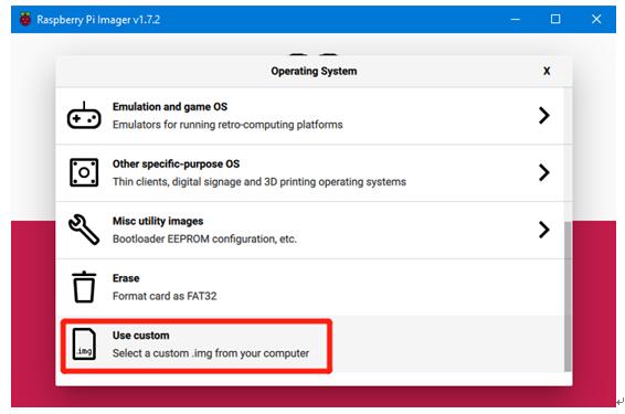
2. Choose OS.
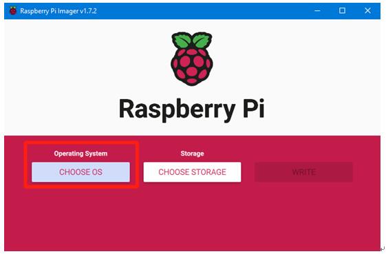
3. Select "Use custom", then select the image that you downloaded.
4.3.2. For balenaEtcher
1. Insert a MicroSD card to your computer through a card reader.
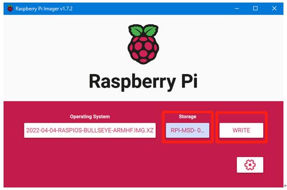
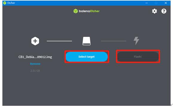
2. Select the image that you downloaded.
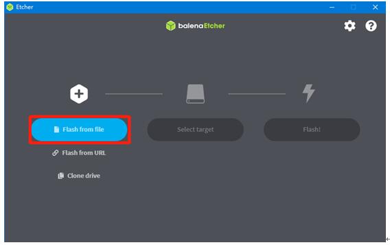
3. Select the MicroSD card and click "WRITE" (WRITE the image will format the MicroSD card. Be careful not to select the wrong storage device, otherwise the data will be formatted.)
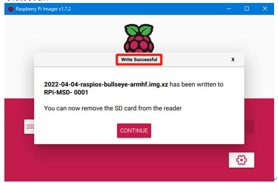
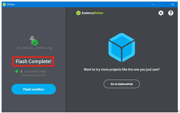
4. Wait for the writing to finish.
五. Configure Network
5.1 Ethernet Cable
Plug-and-play with an Ethernet cable, no additional setup required.
5.2 WiFi Setting
After successfully writing the OS image, the MicroSD card will have a FAT32 partition recognized by the computer and a configuration file named "system.cfg" under this partition.
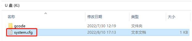
Open with Notepad, replace WIFI-SSID with your WiFi name, and PASSWORD with your password.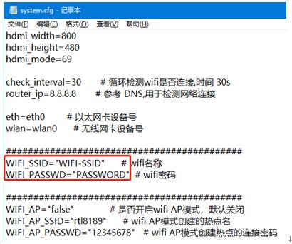
六. Configure Motherboard
6.1 SSH Connect to Device with CB1 Installed
1. Install the SSH application Mobaxterm: https://mobaxterm.mobatek.net/download-home-edition.html
2. Insert the MicroSD card to the motherboard, and wait for the system to load after power on, approx. 1-2 minutes.
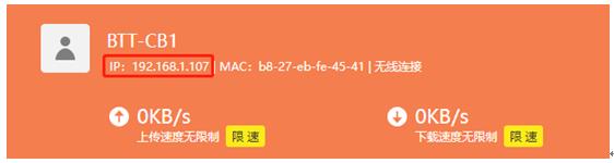
3. The device with CB1 installed will automatically be assigned an IP after being successfully connected to the network.
4. Find the IP address on your router page.
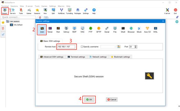
5. Open Mobaxterm and click "Session", and click "SSH", enter the IP you got in step 3 into Remote host, and click "OK". (Note: your computer and the printer needs to be in the same network.)
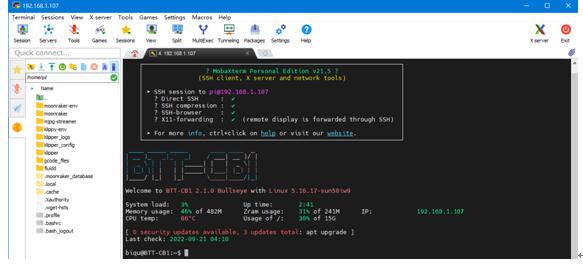
6. Login as: biqu, password: biqu.
6.2 Compile MCU Firmware
1. After SSH is successfully connected to the device with CB1 installed, enter in the terminal:
cd ~/klipper/
make menuconfig
Compile the firmware with the corresponding motherboard configuration, here is the Manta M4P example:
* [*] Enable extra low-level configuration options
* Micro-controller Architecture (STMicroelectronics STM32) --->
* Processor model (STM32G0B1) --->
* Bootloader offset (8KiB bootloader) --->
* Clock Reference (8 MHz crystal) --->
* Communication interface (USB (on PA11/PA12)) --->
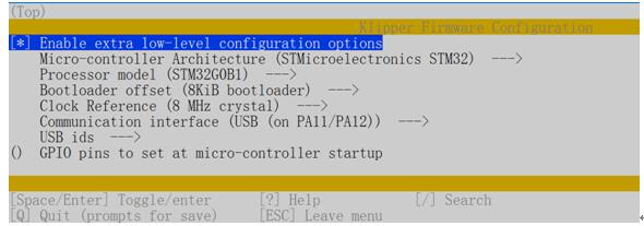
2. Press q to exit, and Yes when asked to save the configuration.
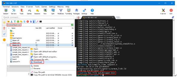
3. Run make to compile firmware, "klipper.bin" file will be generated in home/pi/klipper/out folder when make is finished, download it onto your computer using the SSH application.
七. Cautions
· All unplugging and plugging operations should be performed under the condition of power off, except for HDMI, USB, and RJ45.
· Pay attention to the heat dissipation of CB1. If the running application consumes too many system resources, the CB1 will get hot quite seriously.
If you encounter other problems during use, feel free to contact us, and we are answering them carefully; any good opinions or suggestions on our products are welcome, too and we will consider them carefully.