- sales/support
Google Chat: zj734465502@gmail.com
- sales
+86-0755-88291180
- sales01
sales01@spotpear.com
- sales02
dragon_manager@163.com
- support
services01@spotpear.com
- CEO-Complaints
manager01@spotpear.com
- sales/support
WhatsApp:13246739196
- HOME
- >
- ARTICLES
- >
- Common Moudle
- >
- GSM-GPS
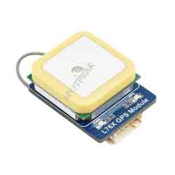
L76K GPS Module User Guide
Introduction
L76K is a multi-satellite system (GPS, BeiDou, GLONASS, QZSS), multi-system joint positioning and single system independent positioning, supports AGNSS function, built-in low noise amplifier and surface acoustic filter, can provide users with fast and accurate, GNSS module with high-performance positioning experience.
This module supports Raspberry Pi, STM32, Arduino, Raspberry Pi Pico and ESP32 control demo.
Interface
| Interface | Description |
|---|---|
| VCC | Power supply (2.7V~5V) |
| GND | Ground |
| TX | UART data output |
| RX | UART command input |
| PPS | Status indication (output second pulse if the positioning is successful) |
NMEA0183
- The host control output NMEA0183 information from the serial port and analyzes NMEA 0183 sentence to output the information.
- NMEA 0183 is a standard format developed by the National Marine Electronics Association for marine electronic equipment. It has now become a unified RTCM (Radio Technical Commission for Maritime Services) standard protocol for GPS navigation equipment.
- NMEA 0183 includes 7 protocol frames including $GPZDA, $GPRMC, $GPVTG, $GPGNS, $GPGGA, $GPGSA, $GPGSV*3, $GPGLL, $GPGST, among which the first two characters followed by $ represent the country or region. For example, GPGGA stands for American GPS, BDGGA stands for China Beidou, GLGGA stands for Russia GLONASS, GAGGA stands for EU Galileo, and GNGGA stands for multi-satellite joint positioning.
- Take $GPRMC as an example to briefly describe the information represented by each part of the protocol frame. Please refer to the NMEA 0183 manual for the other 6 protocol frames.
Recommended Minimum Specific GPS/TRANSIT Data (RMC) recommended positioning information
$GPRMC,<1>,<2>,<3>,<4>,<5>,<6>,<7>,<8>,<9>,<10>,<11>,<12> *hh<CR><LF>
$GNRMC,010555.000,A,2232.4682,N,11404.6748,E,0.00,125.29,230822,,,D*71
<1> UTC time, hhmmss.sss (hour, minute, second) format
<2> Positioning state, A=valid positioning, V=invalid positioning
<3> Latitude ddmm.mmmm (degrees and minutes) format (the front 0 will also be transmitted)
<4> Latitude hemisphere N (Northern Hemisphere) or S (Southern Hemisphere)
<5> Longitude dddmm.mmmm (degrees and minutes) format (the preceding 0 will also be transmitted)
<6> Longitude hemisphere E (East longitude) or W (West longitude)
<7> Ground speed (000.0~999.9 knots, the preceding 0 will also be transmitted)
<8> Ground heading (000.0~359.9 degrees, with true north as the reference, the preceding 0 will also be transmitted)
<9> UTC date, ddmmyy (day month year) format
<10> Magnetic declination (000.0~180.0 degrees, the previous 0 will also be transmitted)
<11> Magnetic declination direction, E (East) or W (West)
<12> Mode indication (only NMEA0183 version 3.00 output, A=autonomous positioning, D=difference, E=estimation, N=data invalid)
*hh: The last check code *hh is the data used for parity. In normal use, it is not necessary, but when there is strong electromagnetic interference in the surrounding environment, it is recommended to use. hh represents the bitwise XOR value of all characters of "$" and "*" (excluding these two characters). Individual manufacturers define their own statement format starting with "$P", followed by a 3-character manufacturer ID number, followed by a custom data body.
PCAS Sentence
PCAS sentences are NMEA-specific sentences defined by chip suppliers.
| Statement | Description | Example | Function |
|---|---|---|---|
| $PCAS01,<CMD>*<Checksum> | configure NMEA serial port baud rate | $PCAS01,1*1D | set serial port baud rate to 9600 <CMD>The following baud rates are supported: |
| $PCAS02,<Interval>*<Checksum> | set positioning frequency | $PCAS02,1000*2E | set positioning frequency to 1Hz <Interval>Positioning interval: |
| $PCAS03,<nGGA>,<nGLL>,<nGSA>,<nGSV>,<nRMC>,<nVTG>,<nZDA>,<nANT>,<Res>,<Res>,<Res>,<Res >,<Res>,<Res>*<Checksum> | Configure NMEA sentence output type and output frequency | $PCAS03,1,1,1,1,1,1,1,1,0,0,,, 0,0*02 | Enable GGA, GLL, GSA, GSV, RMC, VTG, ZDA, ANT sentence output in NMEA output (see L76K&L26K GNSS protocol specification: 2.3 PCAS sentence (special sentence)) |
| $PCAS04,<Mode>*<Checksum> | Configure Galaxy | $PCAS04,3*1A | Configure Galaxy as GPS+BeiDou <Mode>GNSS galaxy configuration: |
| $PCAS10,<Flag>*<Checksum> | Restart module | $PCAS10,0*1C | Hot start <Flag>Restart mode: |
Note: After changing the configuration content, you need to modify the checksum <Checksum> accordingly. For more details, you can refer to Quectel_L76KL26K_GNSS.
Working in Windows
- Connect the GPS antenna and the USB to the UART module (not included), and then connect to the computer. as the picture shows. After connecting, the power indicator light (PWR) is always on.
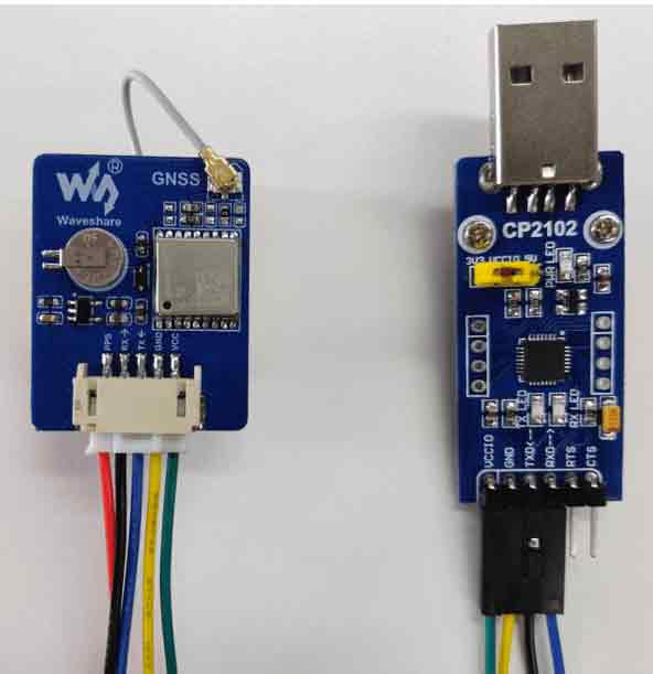
Note: The red cable is not VCC, and the black cable is not GND.
| Module | USB To UART |
|---|---|
| VCC | 5V/3.3V |
| GND | GND |
| RX | TXD |
| TX | RXD |
| PPS | N/A |
- Open the computer serial port debugging assistant, set the corresponding serial port number (com5 here), baud rate 9600, 8 data bits, 1 stop bit, no parity bit, and no flow control.
Sscom can be downloaded Here.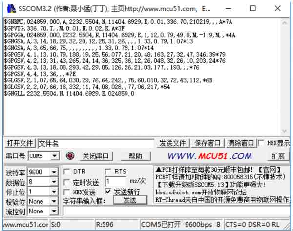
Note:
1. Due to the instability of GPS indoor search, please put the module or antenna next to the balcony or window, or conduct experiments directly outdoors.
2. The first positioning of the module (cold start), under normal circumstances (outdoors, good weather, no large building block), takes 35 seconds to successfully locate, please wait patiently. If the weather conditions are bad, it may take longer to locate, or even fail to locate.
Download U-centersetup v8.12.zip, unzip it, and open it for installation. Run the program, click the Receiver menu, select Port, and set the actual serial port number, Baudrate: 9600. Click (connect button) to connect to the GPS module, and the u-center will display various information, as shown below: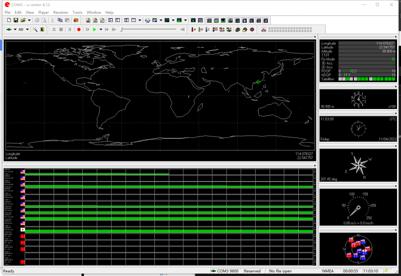
Working With Raspberry Pi
Provide C and Python demos for control in Raspberry Pi.
Enable UART Port (Skip if enabled)
Enable the Raspberry Pi terminal and input the following commands to enter the interface.
sudo raspi-config
Choose Interfacing Options -> Serial, close the shell visit, and enable the serial port of the hardware: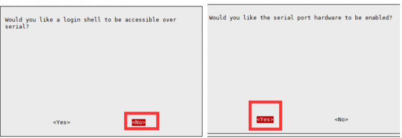
Hardware Connection
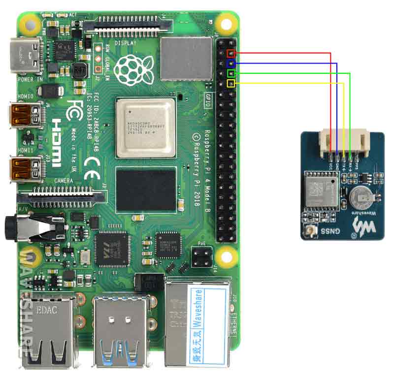
| Module | RaspberryPi |
|---|---|
| VCC | 5V |
| GND | GND |
| TX | P15 |
| RX | P14 |
| PPS | NC |
Minicom Debug
Download and install minicom tool:
sudo apt-get install minicom
The corresponding serial port number for the position hardware serial port:
ls -l /dev/serial*
If the system has used the serial port and has been modified, there are two scenarios:
The default state after enabling the UART function: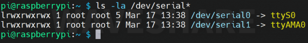
The state after modifying the UART config.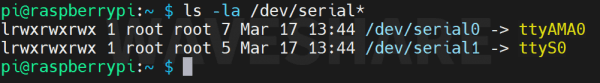
Need to find the serial port number corresponding to serial0 (that is, the serial port on GPIO), as shown in Figure 1, the serial port number is ttyS0, and Figure 2 is ttyAMA0; use minicom to open the serial port:
sudo minicom -D /dev/ttyS0 -b 9600
-D stands for port. If the serial port number in the previous step is ttyAMA0, then it is:
sudo minicom -D /dev/ttyAMA0 -b 9600
The default baud rate of minicom is 115200, if you need to set the baud rate to 9600, add the parameter -b 9600.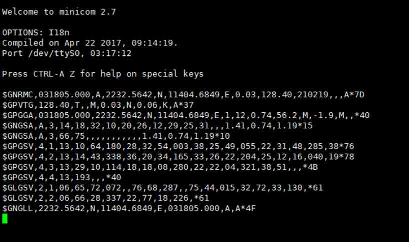
Exit: Ctrl+A then press X alone, YES to enter.
Download and Run the Test Demo
Download Demo
cd
sudo apt-get install unzip -y
sudo wget https://www.waveshare.com/w/upload/0/05/L76K_GPS_Module_code.zip
sudo unzip L76K_GPS_Module_code.zip -d ./L76K_GPS_Module_code
sudo chmod 777 -R ./L76K_GPS_Module_code
cd ./L76K_GPS_Module_code
Or click to download the sample demo, unzip it, and put it into the Raspberry Pi.
Environment Config
Install the related function library of the demo.
BCM2835
#Open the Raspberry Pi terminal and run the following command
wget http://www.airspayce.com/mikem/bcm2835/bcm2835-1.71.tar.gz
tar zxvf bcm2835-1.71.tar.gz
cd bcm2835-1.71/
sudo ./configure && sudo make && sudo make check && sudo make install
# For more information, please refer to the official website: http://www.airspayce.com/mikem/bcm2835/
WiringPi
Open the Raspberry Pi terminal and run the following commands:
cd
sudo apt-get install wiringpi
#For Raspberry Pi systems after May 2019 (earlier ones do not need to be executed), an upgrade may be required:
wget https://project-downloads.drogon.net/wiringpi-latest.deb
sudo dpkg -i wiringpi-latest.deb
gpio -v
# Run gpio -v and version 2.52 will appear, if there is no installation error
The #Bullseye branch system uses the following commands:
git clone https://github.com/WiringPi/WiringPi
cd WiringPi
./build
gpio -v
# Run gpio -v and version 2.70 will appear if there is no installation error
Python
The new version of the Raspberry Pi system needs to install the GPS data analysis library to run the python3 program.
cd L76K_GPS_Module_code/RaspberryPi/python3/micropyGPS-master
sudo python setup.py install
#Wait for the library installation to complete
If the old system only supports Python2, the function library is required.
sudo apt-get update
sudo pip install RPi.GPIO
sudo apt-get install python-serial
C Demo
cd C
make clean
make
sudo ./main
Baidu Coordinates is the converted Baidu map coordinates, copy the coordinates to http://www.gpsspg.com/maps.htm, select Baidu map on the left, and you can see your location (if you go directly to "Baidu Pickup Coordinate System" you need Swap the positions of the two latitude and longitude numbers).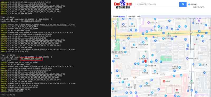
Python 3 Demo
cd python
sudo python main.py
Expected Result
It takes 35 seconds for the module to be positioned for the first time.
The front is the raw data output by the module.
Time is the time output by L76X GPS Module.
Latitude and longitude are the output latitude and longitude and latitude and longitude direction.
Baidu Coordinates is the converted Baidu map coordinates, copy the coordinates to http://www.gpsspg.com/maps.htm, select Baidu map on the left, and you can see your location (if you go directly to "Baidu Pickup Coordinate System" you need Swap the positions of the two latitude and longitude numbers).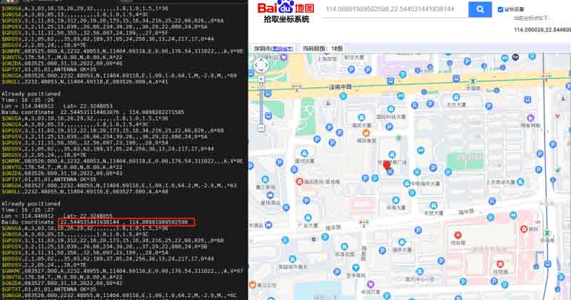
Python 2 Demo
cd python
sudo python main.py
Expected Result
It takes 35 seconds for the module to be positioned for the first time.
The front is the raw data output by the module.
Time is the time output by L76X GPS Module.
Latitude and longitude are the output latitude and longitude and the directions of latitude and longitude.
Baidu Coordinates is the converted Baidu map coordinates, copy the coordinates to http://www.gpsspg.com/maps.htm, select Baidu map on the left, and you can see your location (if you go directly to "Baidu Pickup Coordinate System" you need Swap the positions of the two latitude and longitude numbers).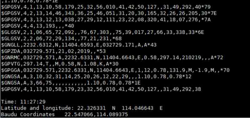
Working With Arduino
This demo has been verified on Arduino MEGA2560.
Click to download the sample demo or download it in the Resource.
Hardware Connection
| Module | Arduino |
|---|---|
| VCC | 5V |
| GND | GND |
| TX | RX2 |
| RX | TX2 |
| PPS | NC |
Demo Usage
Choose the Arduino mega2560 development board and the corresponding port, and upload the demo after verification.
The first position for the module will take 35 seconds.
Open SSCOM and set the baud rate as 9600.
The original data is output by the module at first.
Time is the time of L76X GPS Module output.
Lat and Lon are the output latitude and longitude and latitude and longitude directions. B_Lat and B_Lon are the converted Baidu map coordinates, copy the coordinates to http://api.map.baidu.com/lbsapi/getpoint/, you can see your location (the coordinate format is longitude Lat first, latitude Lon after, separated by commas in the middle).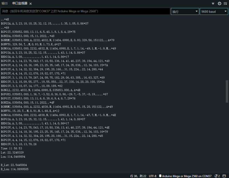
The Arduino uno demo is also included in the file, but the data accuracy of this platform is insufficient, and only the time in the satellite data is displayed. If you want other information, you can modify the program yourself.
Working With Raspberry Pi Pico
Hardware Connection
| Module | Raspberry Pi Pico |
|---|---|
| VCC | 5V |
| GND | GND |
| TX | GP1 |
| RX | GP0 |
| PPS | NC |
Environment Building
We test the demo with Thonny in this tutorial, click to download the related IDE and open Thonny.
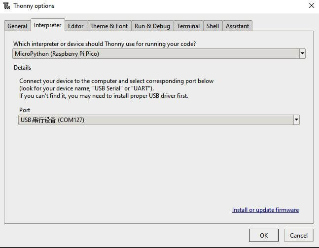
- Please refer to the official document to set up the python environment. Choose a Raspberry Pi Pico device in Tools->Options->Interprete. As shown below:
Download Demo
1. Click to download the sample demo.
2. Unzip the sample demo.
3. Open Thonny, first confirm that you have connected to pico, then open the decompressed program path in the upper left corner, right-click on the pico folder, and select upload, as shown in the figure: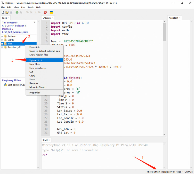
How To Use the Demo
1. Open Thonny IDE, choose the Pico directory, double-click coordinate_convert.py file, and then run the demo, as shown below: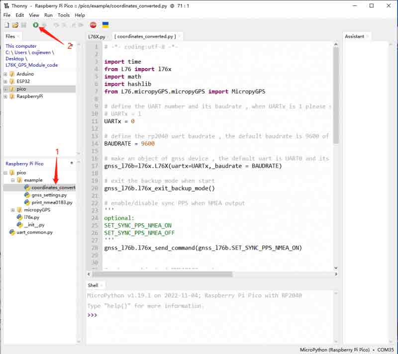
2. Under sunny conditions, the L76K will obtain the positioning information about 30 seconds after it is powered on, as shown in the following figure when running the demo.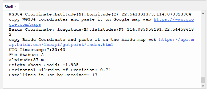
3. The user can copy the positioning information displayed in the terminal in Thonny, and use Google Map and Baidu Map to mark the coordinates.
ESP32
Hardware Connection
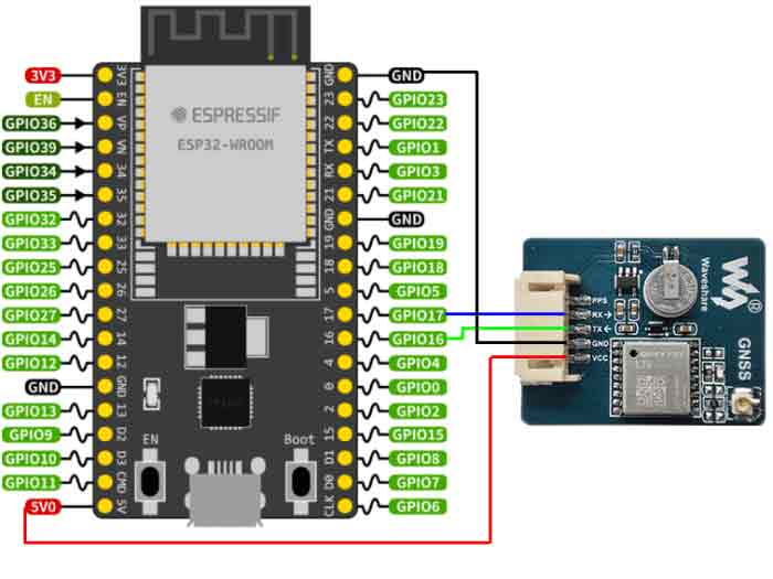
| Module | ESP32 |
|---|---|
| VCC | 5V |
| GND | GND |
| TX | P16 |
| RX | P17 |
| PPS | NC |
Environment Building
Install ESP32 plug-in On Arduino IDE
1. Open the Arduino IDE, click on the file in the upper left corner, and select Preferences.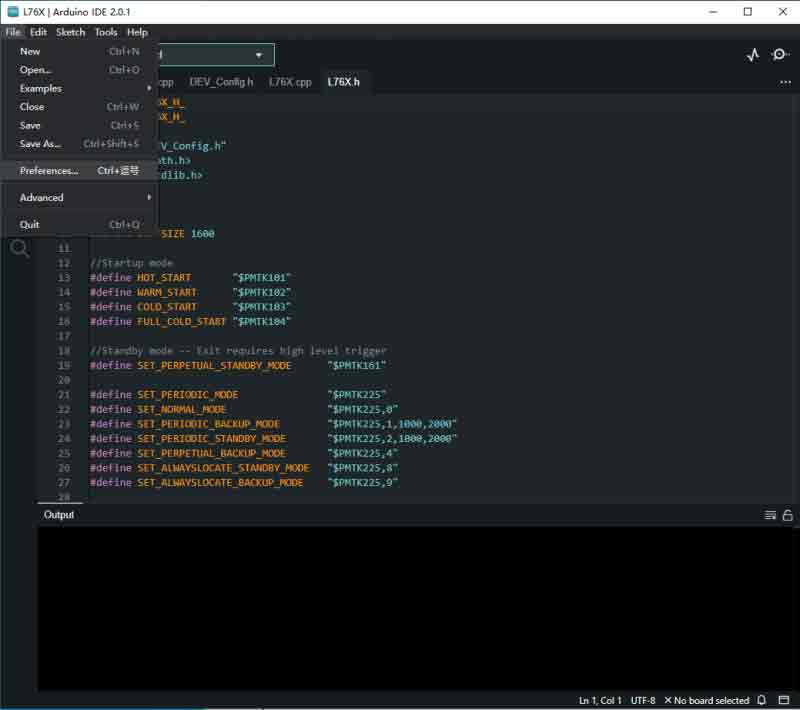
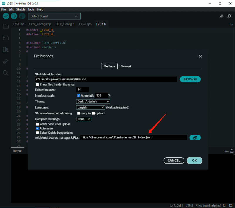
2. Add the following link in the additional development board manager URL, then click OK.
https://dl.espressif.com/dl/package_esp32_index.json
Note: If you already have the ESP8266 board URL, you can separate the URLs with commas like this:
https://dl.espressif.com/dl/package_esp32_index.json,http://arduino.esp8266.com/stable/package_esp8266com_index.json
3. Download package and copy the packages file to the following path:
C:\Users\xutong\AppData\Local\Arduino15
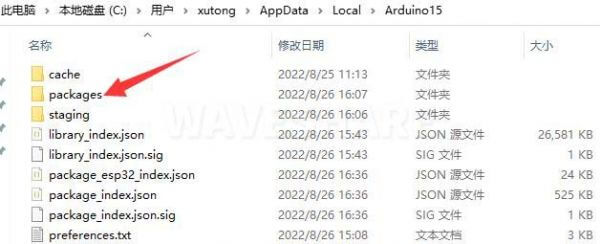
Note: Replace the username: xutong with your own username.
How To Use the Demo
- Download the demo and unzip it, use the configured Arduino IDE to open the L76X.ino file in the ESP32 directory, and wait for all the files to be loaded.
- Use the data cable to connect the esp32 development board to the computer, and select the correct development board model and port number.
- Here we take the ESP32-S chip development board as an example: Click in turn: Tools->Development Board->esp32->ESP32 Dev Module, and select the corresponding port number.
- Click "Verify" in the upper left corner, wait for the verification to complete without error, and then click "Upload".
- After the upload is complete, the demo runs automatically. Click: Tools->Serial Monitor in turn, and you can observe the running effect of the demo in the serial monitor window:
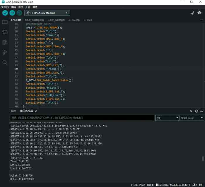
It takes 35 seconds for the module to be positioned for the first time. (It may be longer if the signal condition is not good). The front is the raw data output by the module. Time is the time output by L76X GPS Module. "Lat" and "Lon" are the output latitude and longitude and the directions of latitude and longitude.
B_Lat and B_Lon are the converted Baidu map coordinates, copy the coordinates to http://api.map.baidu.com/lbsapi/getpoint/, and you can see your location (the coordinate format is longitude Lat first, latitude Lon after, separated by commas in the middle).
Jetson Nano
This example has been verified on the JETSON-NANO-DEV-KIT development board that programs the ubuntu system.
Hardware Connection
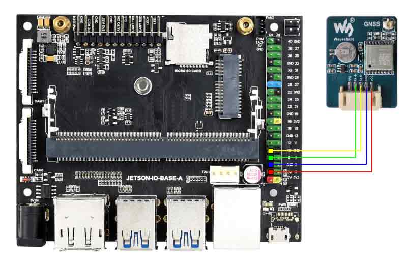
| Module | JETSON-NANO-DEV-KIT |
|---|---|
| VCC | 5V |
| GND | GND |
| TX | 10 |
| RX | 8 |
| PPS | NC |
Environment Debug
Install Pip Tool
Install python tool pip with apt-get tool.
sudo apt-get install python3-pip #python3
# After that, you need to enter the user password to verify
sudo apt-get install python2-pip #python2
# After that, you need to enter the user password to verify
Waiting for the installation.
Install python Library
Libraries required by the #python3 program:
sudo pip3 install pyserial #serial port control library
sudo pip3 install settools #install tools
cd jetson/python3/micropyGPS-master
sudo python3 setup.py install #data parsing library
Libraries required by the #python2 program:
sudo pip install pyserial #serial port control library
How To Use the Demo
Enter the directory and run main.py.
cd jetson/python3
sudo python3 main.py
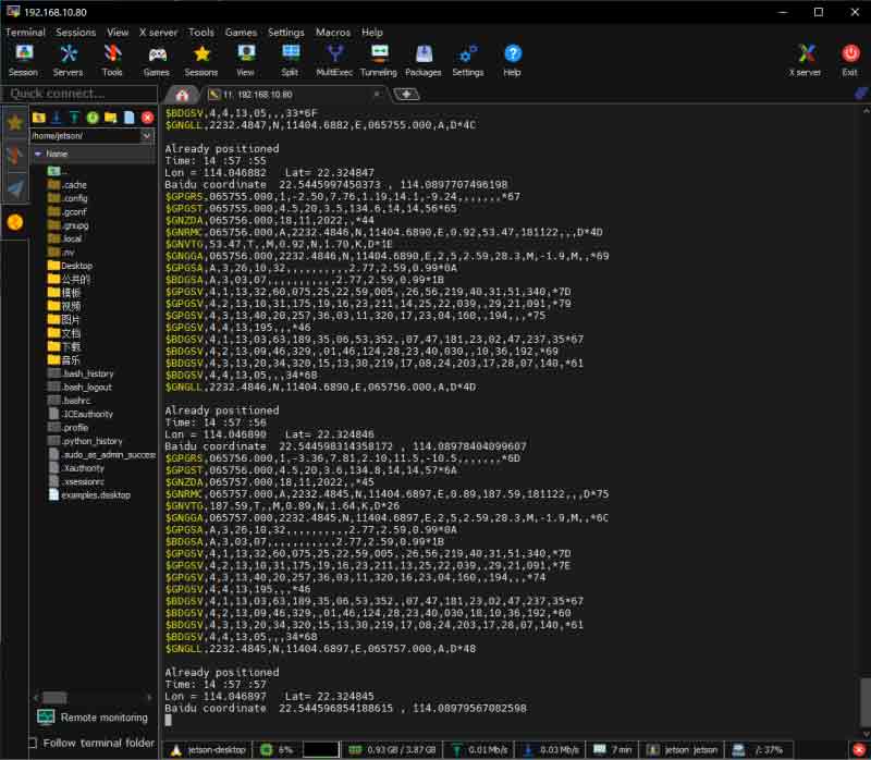
It takes 35 seconds for the module to be positioned for the first time.
The front is the raw data output by the module.
Time is the time output by L76X GPS Module.
Latitude and longitude are the output latitude and longitude and the direction of latitude and longitude.
Baidu Coordinates is the converted Baidu map coordinates, copy the coordinates to http://www.gpsspg.com/maps.htm, select Baidu map on the left, and you can see your location (if you go directly to "Baidu Pickup Coordinate System" you need Swap the positions of the two latitude and longitude numbers).
Parameters
| Model | LC76G(AB) | L76K | L76B |
|---|---|---|---|
| Compatible | |||
| Picture | |||
| GNSS | GPS/GLONASS/Galileo/BDS/QZSS | GPS/GLONASS/BDS/QZSS | GPS/BDS/QZSS |
| Form Factor | LCC | LCC | LCC |
| Dimensions | 9.7×10.1×2.4 | 9.7×10.1×2.4 | 9.7×10.1×2.4 |
| Weight (g) | 0.6 | 0.4 | 0.5 |
| Normal Operating Temperature | -40℃ ~+85℃ | -40℃ ~+85℃ | -40℃ ~+85℃ |
| Storage Temperature | -40℃ ~+90℃ | -40℃ ~+90℃ | -40℃ ~+90℃ |
| Main Feature | |||
| Function | Standard | Standard | Example |
| Chip | AG3352Q | AT6558R | MT333 |
| L1 Receiver (Channel) | 47 tracking ch | 32 tracking ch/72 acquisition ch | 22 tracking ch/66 acquisition ch |
| L1 Receiver SBAS | Support | N/A | Support |
| A-GNSS | Support | Support | Support |
| Sensitivity (Auto-aquisition) | -147dBm | -148dBm | -148dBm |
| Sensitivity (re-acquisition) | -159dBm | -160dBm | -160dBm |
| Sensitivity (tracking) | -166dBm | -162dBm | -163dBm |
| TTFF (Time To Fisrt Fix) Cold Starts | 26s, Autonomous 12s, with EASY™ 5s,with EPO™ | 30s, Autonomous 5.5s, With AGNSS | 35s, Autonomous 15s, with EASY™ |
| TTFF (Time To Fisrt Fix) Warm Starts | 20s, Autonomous 2s, with EASY™ | / | 30s, Autonomous 5s, with EASY™ |
| TTFF (Time To Fisrt Fix) Hot Starts | 1s | 2s | 1s |
| Position Accuracy | 1.5m CEP | 2.0m CEP | 2.5m CEP |
| Velocity Accuracy | 0.1m/s | 0.1m/s | 0.1m/s |
| Acceleration Accuracy (Max) | 0.1m/s² | 0.1m/s² | 0.1m/s² |
| Timing Accuracy | 100ns | 30ns | 10ns |
| Update Rate (Max) | 10Hz | 5Hz | 10Hz |
| Default baudrate | 115200bps | 9600bps | 9600bps |
| Geo-fence | ⚪ | / | ⚪ |
| Interference Detection | ⚪ | / | ⚪ |
| Anti-jamming | ⚪ | / | ⚪ |
| LNA | ⚪ | ⚪ | ⚪ |
| Electrical Parameters | |||
| Power Supply | 2.55to3.6V | 2.7Vto3.4V | 2.8Vto4.3V |
| Power Consumption (Acquisition) | 36mA(G3B) | 29mA (GPS+BDS) | 29mA (GPS+BDS) |
| Power Consumption (Tracking) | 36mA(G3B) | 29mA (GPS+BDS) | 18mA (GPS+BDS) |
| Power Consumption (RTC backup/low power consumption | 13μA | 8μA | 7μA |
| Interface | |||
| UART | ⚪ | ⚪ | ⚪ |
| IIC (NMEA) | ⚪ | / | ⚪ |
| Reset | ⚪ | ⚪ | ⚪ |
| Timing Pulse | ⚪ | ⚪ | ⚪ |
| Antenna | |||
| Short circuit and open circuit detection | ⚪ | ⚪ | ⚪ |
| Antenna Type | Active, Passive | Active, Passive | Active, Passive |
| Antenna Power Supply | External or Internal | External or Internal | External or Internal |