- sales/support
Google Chat: zj734465502@gmail.com
- sales
+86-0755-88291180
- sales01
sales01@spotpear.com
- sales02
dragon_manager@163.com
- support
services01@spotpear.com
- CEO-Complaints
manager01@spotpear.com
- sales/support
WhatsApp:13246739196
- HOME
- >
- ARTICLES
- >
- Raspberry Pi
- >
- Raspberry Pi LCD
- >
- e-Paper
Raspberry Pi 7.3inch e-Paper (F) User Guide
Parameters
| Dimensions | 7.3inch |
| Outline dimension (driver board) | 65.0mm × 30.5mm |
| Display dimension | 160.0mm × 96.0mm |
| Outline dimensions | 170.20mm × 111.20mm × 0.91mm |
| Operating voltage | 3.3V / 5V(Both power supply and signal need to be 5V) |
| Communication interface | SPI |
| Dot pitch | 0.2mm × 0.2mm |
| Resolution | 800 × 480 |
| Display color | Black, White, Green, Blue, Red, Yellow, Orange |
| Grey scale | 2 |
| Refresh time | 35s |
| Refresh power | 49.4mW(typ.) |
| Standby current | < 0.01uA (almost none) |
- Refresh time: The refresh time is the experimental results, the actual refresh time will have errors, and the actual effect shall prevail. There will be a flickering effect during the global refresh process, this is a normal phenomenon.
- Power consumption: The power consumption data is the experimental results. The actual power consumption will have a certain error due to the existence of the driver board and the actual use situation. The actual effect shall prevail.
SPI Communication Timing
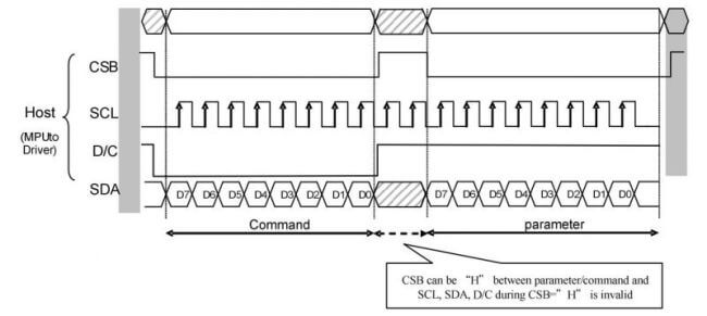
- CSB (CS): Slave chip select, when CS is low, the chip is enabled.
- SCL (SCK/SCLK): UART clock signal.
- D/C (DC): data/command control pin, writes commands in low level; writes data/parameter in high level.
- SDA (DIN): serial data signal.
- Timing: CPHL=0, CPOL=0 (SPI0)
【Remarks】For more information about SPI, you can search for information online.
Working Principle
This product is an E-paper device adopting the image display technology of Microencapsulated Electrophoretic Display, MED. The initial approach is to create tiny spheres, in which the charged color pigments are suspended in the transparent oil and would move depending on the electronic charge. The E-paper screen display patterns by reflecting the ambient light, so it has no background light requirement. Under ambient light, the E-paper screen still has high visibility with a wide viewing angle of 180 degrees. It is the ideal choice for E-reading.
Programming Principles
- For computers, pictures are composed of pixels, and the space occupied by each pixel determines the possible state (color) of the pixel. The simplest black-and-white picture only occupies one bit per pixel. (1Bit), either 0 or 1 is either black or white. As the color increases, the space occupied by each pixel becomes larger and larger, eight bits, sixteen bits, twenty-four bits...
- This module uses a non-standard 24-bit image. If you need to make your own images, you can refer to the "Image Processing" chapter.
- We define the pixels in a monochrome picture, 0 is black and 1 is white.
- White:□: Bit 1
- Black:■: Bit 0
- White:□: Bit 1
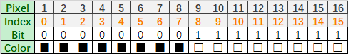
- The dot in the figure is called a pixel. As we know, 1 and 0 are used to define the color, therefore we can use one bit to define the color of one pixel, and 1 byte = 8pixels
- For example, If we set the first 8 pixels to black and the last 8 pixels to white, we show it by codes, they will be 16-bit as below:
For the computer, the data is saved in MSB format: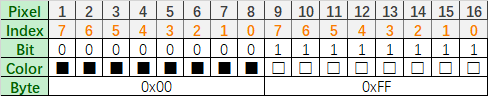
So we can use two bytes for 16 pixels.
- Now suppose we have seven colors, so we need at least three bits of data to represent all colors, but for the operation, we add a 0 in front of it, that is, use four bits of data to represent the color of a pixel, such a byte (1Byte) Two pixels can be represented. In fact, the controller of this module adopts this method.
| Color | BIN | HEX | The color (reference) |
| Black | 0b0000 | 0x0 | |
| White | 0b0001 | 0x1 | |
| Green | 0b0010 | 0x2 | |
| Blue | 0b0011 | 0x3 | |
| Red | 0b0100 | 0x4 | |
| Yellow | 0b0101 | 0x5 | |
| Orange | 0b0110 | 0x6 |
For example, if you want to display four colors, green, yellow, red and orange, it should be like as below:
| Pixel | 1 | 2 | 3 | 4 | ||||||||||||
| Bit | 0 | 1 | 2 | 3 | 4 | 5 | 6 | 7 | 8 | 9 | 10 | 11 | 12 | 13 | 14 | 15 |
| Data | 0 | 0 | 1 | 0 | 0 | 1 | 0 | 1 | 0 | 1 | 0 | 0 | 0 | 1 | 1 | 0 |
| Color | ||||||||||||||||
For a computer, its data storage method is high-order first, low-order last, and a byte has only eight bits, so it is stored in a byte like this:
| Pixel | 1 | 2 | 3 | 4 | ||||||||||||
| Bit | 7 | 6 | 5 | 4 | 3 | 3 | 1 | 0 | 7 | 6 | 5 | 4 | 3 | 2 | 1 | 0 |
| Data | 0 | 0 | 1 | 0 | 0 | 1 | 0 | 1 | 0 | 1 | 0 | 0 | 0 | 1 | 1 | 0 |
| Color | ||||||||||||||||
| Byte | 0x25 | 0x46 | ||||||||||||||
Precautions
- For E-paper displays that support partial refresh, please note that you cannot refresh them with the partial refresh mode all the time. After refreshing partially several times, you need to fully refresh EPD once. Otherwise, the display effect will be abnormal, which cannot be repaired!
- It is a normal phenomenon that the three-color EPD will have a certain color difference in different batches. Hence, It is recommended to use the program to clear all the pictures on the EPD and store it facing up. Please clear the screen several times before powering on.
- Note that the screen cannot be powered on for a long time. When the screen is not refreshed, please set the screen to sleep mode or power off it. Otherwise, the screen will remain in a high voltage state for a long time, which will damage the e-Paper and cannot be repaired!
- When using the e-Paper display, it is recommended that the refresh interval be at least 180s, and refresh at least once every 24 hours. If the e-Paper is not used for a long time, you should use the program to clear the screen before storing it. (Refer to the datasheet for specific storage environment requirements.)
- After the screen enters sleep mode, the sent image data will be ignored, and it can be refreshed normally only after initializing again.
- Control the 0x3C or 0x50 (refer to the datasheet for details) register to adjust the border color. In the demo, you can adjust the Border Waveform Control register or VCOM AND DATA INTERVAL SETTING to set the border.
- If you find that the created image data is displayed incorrectly on the screen, it is recommended to check whether the image size setting is correct, change the width and height settings of the image and try again.
- The working voltage of the e-Paper display is 3.3V. If you buy the raw panel and you need to add a level convert circuit for compatibility with 5V voltage. The new version of the driver board (V2.1 and subsequent versions) has added a level processing circuit, which can support both 3.3V and 5V. The old version only supports a 3.3V working environment. You can confirm the version before using it. (The one with the 20-pin chip on the PCB is generally the new version.)
- The FPC cable of the screen is relatively fragile, pay attention to bending the cable along the horizontal direction of the screen when using it, and do not bend the cable along the vertical direction of the screen.
- The screen of e-Paper is relatively fragile, please try to avoid dropping, bumping, and pressing hard.
- We recommend that customers use the sample program provided by us to test with the corresponding development board.
Picture Production
Picture production and conversion of multi-color E-ink.
Preparation
Required software: Adobe PhotoShop CC, Painting
Introduction
- Floyd-Steinberg dithering algorithm is very suitable for showing rich layering when color is less. More color combinations for better shadow rendering of the original image. It is especially suitable for various usage scenarios of e-ink screens.
- The following will introduce how to convert ordinary pictures into Floyd-Steinberg scatter plots.
- If you are interested in the actual algorithm, you can read about our algorithm porting on ESP32 link hereand ESP8266 link here.
Operating Steps
Preparation: Download color sheet to PC, and unzip to get the file as shown below, we are going to use "N-color.act." or "4-color.act".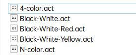
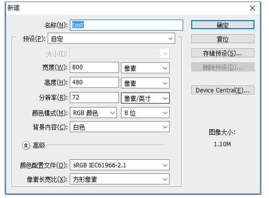
1. New Photoshop project set the width and height according to the actual resolution of the e-Paper display, the color mode uses RGB. The resolution of this module is 800*480. Change the width to 800 pixels and the height to 480 pixels.
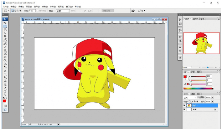
2. Prepare the corresponding picture, copy it into the project, and adjust the parameters such as size and contrast (similar to the steps for processing pictures in general Photoshop).
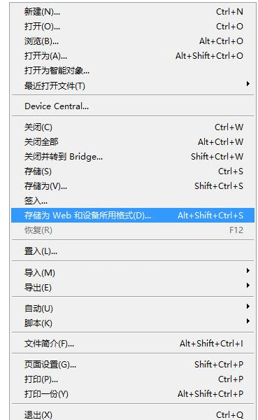
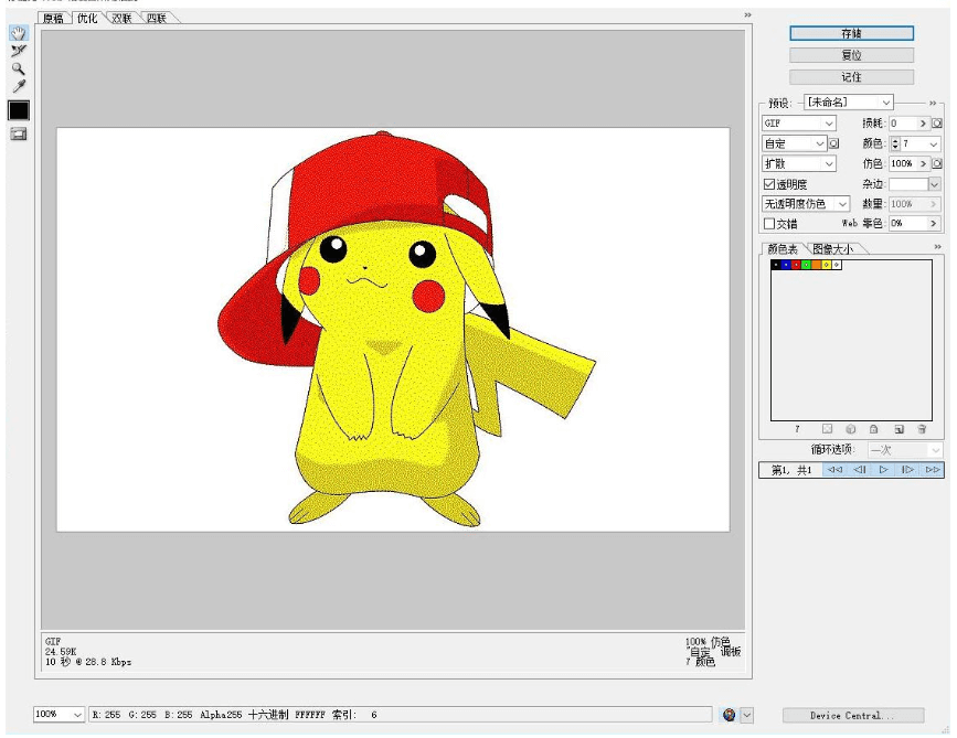
3. Select File->Save for Web and Devices.
4. Select the color table as shown below. Load the color table provided in Preparation.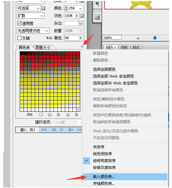
5. For seven-color pictures, load N-color. act, then click Save and save as a gif file. Then convert it into BMP format and use it on this module.
For four-color images, load 4-color. act, then click Save and save as a gif file. Then convert it into BMP format and use it on this module.
6. Open the gif file with Paint and save it as a 24-bit BMP image. 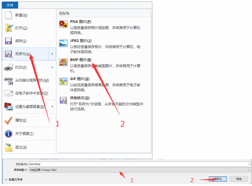
7. By now, the color picture available for this module has been made, and it can be put into the SD card of the Raspberry Pi or e-Paper Shield module for use.
Image Data Conversion
Download the Program
- Four-color picture converting demo: Coverterto4colors
- Seven-color picture converting demo: Converterto7colors
- Source code: Convertertocolor
Note: Theis application is provided for your convenience and is open source, our company does not provide technical support for it.
How to Convert
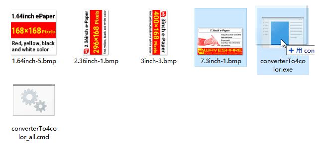
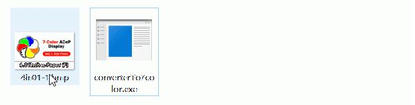
- Put the prepared picture and the corresponding "exe" application in the same folder, and you can put multiple pictures at the same time.
- Drag and drop the picture in the "exe" file, and the program will convert the picture into "a .c" file with a fixed name.
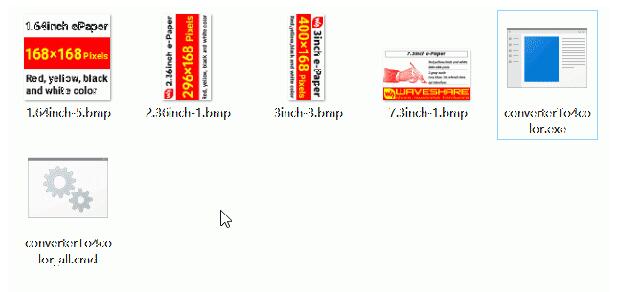
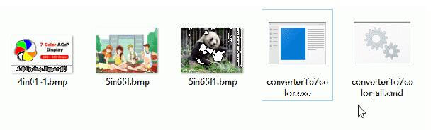
- Double-click the "cmd" file, and the program will convert all the pictures in the folder that meet the size to generate a ".c" file with the corresponding name.
- Click on the image to see the demonstration.
- Four-color single-image demonstration:
- Four-color multi-picture demonstration:
- Seven-color single picture demonstration:
- Seven-color multi-picture demonstration:
Working With Raspberry Pi
Hardware Connection
When connecting the Raspberry Pi, you can directly insert the board into the 40PIN pin header of the Raspberry Pi, and pay attention to the correct pins.
If you choose to connect with an 8PIN cable, please refer to the pin correspondence table below:
| e-Paper | Raspberry Pi | |
| BCM2835 | Board | |
| VCC | 3.3V | 3.3V |
| GND | GND | GND |
| DIN | MOSI | 19 |
| CLK | SCLK | 23 |
| CS | CE0 | 24 |
| DC | 25 | 22 |
| RST | 17 | 11 |
| BUSY | 24 | 18 |
Enable SPI Interface
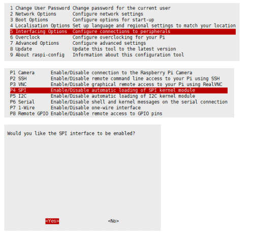
- Open the Raspberry Pi terminal and enter the following command in the config interface:
sudo raspi-config
Choose Interfacing Options -> SPI -> Yes Enable SPI interface
Then reboot your Raspberry Pi:
sudo reboot
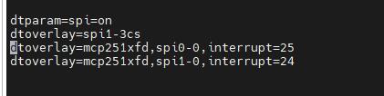
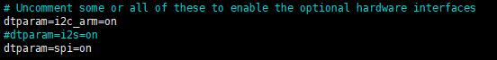
- Check /boot/config.txt, and you can see 'dtparam=spi=on' was written in.
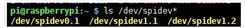
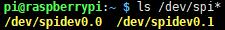
- To make sure SPI is not occupied, it is recommended to close other drivers' coverage. You can use ls /dev/spi* to check whether SPI is occupied. If the terminal outputs /dev/spidev0.1 and /dev/spidev0.1, SPI is not occupied.
C
- Install BCM2835
#Open the Raspberry Pi terminal and run the following command
wget http://www.airspayce.com/mikem/bcm2835/bcm2835-1.71.tar.gz
tar zxvf bcm2835-1.71.tar.gz
cd bcm2835-1.71/
sudo ./configure && sudo make && sudo make check && sudo make install
# For more information, please refer to the official website: http://www.airspayce.com/mikem/bcm2835/
- Install WiringPi (Optional)
#Open the Raspberry Pi terminal and run the following command:
sudo apt-get install wiringpi
#For Raspberry Pi systems after May 2019 (earlier than before, you may not need to execute), you may need to upgrade:
wget https://project-downloads.drogon.net/wiringpi-latest.deb
sudo dpkg -i wiringpi-latest.deb
gpio -v
#Run gpio -v and version 2.52 will appear. If it does not appear, the installation is wrong.

#Bullseye branch system use the following command:
git clone https://github.com/WiringPi/WiringPi
cd WiringPi
./build
gpio -v
# Run gpio -v and version 2.60 will appear. If it does not appear, it means that there is an installation error.
- Download the demo via GitHub (You can skip this step if you have downloaded it.)
git clone https://github.com/waveshare/e-Paper.git
cd e-Paper/RaspberryPi_JetsonNano/
- Download the demo (You can skip this step if you have downloaded it.)
sudo apt-get install p7zip-full
wget  https://www.waveshare.com/w/upload/3/39/E-Paper_code.7z
7z x E-Paper_code.7z -O./e-Paper
cd e-Paper/RaspberryPi_JetsonNano/
- Compile the demo (Note: -j4 is to compile with 4 threads, the numbers can be modified by yourself; EPD=epd7in3f is to specify a macro definition, and epd7in3f corresponds to the test demo in the main function).
# Now at e-Paper/RaspberryPi_JetsonNano
cd c
sudo make clean
sudo make -j4 EPD=epd7in3f
- Run the demo
sudo ./epd
Python
- Install the function library
sudo apt-get update
sudo apt-get install python3-pip
sudo apt-get install python3-pil
sudo apt-get install python3-numpy
sudo pip3 install RPi.GPIO
sudo pip3 install spidev
- Install function library (python2)
sudo apt-get update
sudo apt-get install python-pip
sudo apt-get install python-pil
sudo apt-get install python-numpy
sudo pip install RPi.GPIO
sudo pip install spidev
- Download the demo via GitHub (You can skip this step if you have downloaded it.)
git clone https://github.com/waveshare/e-Paper.git
cd e-Paper/RaspberryPi_JetsonNano/
- Download the demo (You can skip this step if you have downloaded it.)
sudo apt-get install p7zip-full
wget  https://www.waveshare.com/w/upload/3/39/E-Paper_code.7z
7z x E-Paper_code.7z -O./e-Paper
cd e-Paper/RaspberryPi_JetsonNano/
- Run the demo
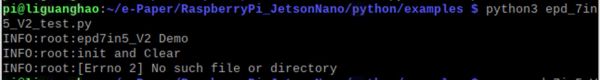
# Make sure it's in e-Paper/RaspberryPi_JetsonNano/
cd python/examples/
python3 epd_7in3f_test.py
Working With Arduino
Hardware Connection
Use an 8PIN cable to connect, please refer to the pin correspondence table below:
| e-Paper | Arduino UNO | Mega2560 |
| VCC | 5V | 5V |
| GND | GND | GND |
| DIN | D11 | D51 |
| CLK | D13 | D52 |
| CS | D10 | D10 |
| DC | D9 | D9 |
| RST | D8 | D8 |
| BUSY | D7 | D7 |
Install IDE
Arduino IDE Windows Install Guide
Run The Demo
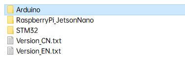
- Download the demo in Resource, unzip it to the "E-Paper_code" directory, and you can see the following content:
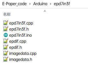
- Open the test demo: E-Paper_code\Arduino\epd7in3f\epd7in3f.ino
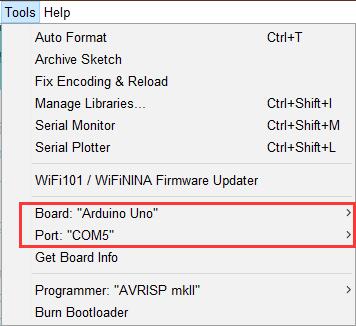
- Select the corresponding Board and Port in the Tools in the Arduino IDE.
- Finally, click upload, the upload is successful as follows (Arduino 1.8.13).

Working With Jetson Nano
Hardware Connection
The 40PIN pin of Jetson Nano is compatible with the 40PIN pin of Raspberry Pi and provides a Jetson.GPIO library with the same API as the RPI.GPIO library of Raspberry Pi, so the serial number connected here is the same as that of Raspberry Pi. The module can be directly inserted into the 40Pin headers of the Jetson Nano when using the 40PIN interface.
If you choose to connect with an 8PIN cable, please refer to the pin correspondence table below:
| e-Paper | Jetson Nano Developer Kit | |
| BCM2835 | Board | |
| VCC | 3.3V | 3.3V |
| GND | GND | GND |
| DIN | 10 (SPI0_MOSI) | 19 |
| CLK | 11 (SPI0_SCK) | 23 |
| CS | 8 (SPI0_CS0) | 24 |
| DC | 25 | 22 |
| RST | 17 | 11 |
| BUSY | 24 | 18 |
C
- Download the demo via GitHub (you can skip this step if you have downloaded it.)
git clone https://github.com/waveshare/e-Paper.git
cd e-Paper/RaspberryPi_JetsonNano/
- Download the test demo: (you can skip this step if you have downloaded it.)
sudo apt-get install p7zip-full
wget  https://www.waveshare.com/w/upload/3/39/E-Paper_code.7z
7z x E-Paper_code.7z -O./e-Paper
cd e-Paper/RaspberryPi_JetsonNano/
- Compile the demo (Note: JETSON is the specified device, and RPI is not specified by default. -j4 is to compile by 4 threads, and the number can be changed by yourself. "EPD=epd7in3f " is to specify a macro definition, and "epd7in3f" corresponds to the test demo in the main function.)
# Now at e-Paper/RaspberryPi_JetsonNano
cd c
sudo make clean
sudo make JETSON -j4 EPD=epd7in3f
- Run the demo
sudo ./epd
Python
- Install function library
sudo apt-get update
sudo apt-get install python3-numpy
sudo apt-get install python3-pip
sudo pip3 install Jetson.GPIO
- Download the demo via GitHub (you can skip this step if you have downloaded it.)
git clone https://github.com/waveshare/e-Paper.git
cd e-Paper/RaspberryPi_JetsonNano/
- Download the demo (you can skip this step if you have downloaded it.)
sudo apt-get install p7zip-full
wget  https://www.waveshare.com/w/upload/3/39/E-Paper_code.7z
7z x E-Paper_code.7z -O./e-Paper
cd e-Paper/RaspberryPi_JetsonNano/
- Run the demo
# Make sure it's in e-Paper/RaspberryPi_JetsonNano/
cd python/examples/
python3 epd_7in3f_test.py
Working With Sunrise X3 Pi
Hardware Connection
When connecting the Sunrise X3 Pi, you can directly insert the board into the 40PIN pin header of the Sunrise X3 Pi, and pay attention to the correct pins.
If you choose to connect with an 8PIN cable, please refer to the pin correspondence table below:
| e-Paper | Sunrise X3 Pi | |
| BCM | Board | |
| VCC | 3.3V | 3.3V |
| GND | GND | GND |
| DIN | MOSI | 19 |
| CLK | SCLK | 23 |
| CS | CE0 | 24 |
| DC | 25 | 22 |
| RST | 17 | 11 |
| BUSY | 24 | 18 |
Enable SPI
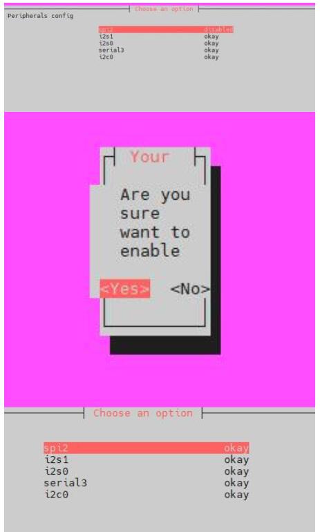
- SPI is enabled by default. If you have disabled it, you can enable it by following the steps below.
- Enter the command: sudo srpi-config
Python
- The corresponding library has been installed in the function. If you uninstall it accidentally, please use the following command to install it.
sudo apt-get update
sudo apt-get install python-pip
sudo apt-get install python-pil
sudo apt-get install python-numpy
sudo pip install Hobot.GPIO
sudo pip install spidev
- Download the demo via GitHub (skip this step if you have downloaded it).
git clone https://github.com/waveshare/e-Paper.git
cd e-Paper/RaspberryPi_JetsonNano/
- Download the demo (skip this step if you have downloaded it).
sudo apt-get install p7zip-full
wget  https://www.waveshare.com/w/upload/3/39/E-Paper_code.7z
7z x E-Paper_code.7z -O./e-Paper
cd e-Paper/RaspberryPi_JetsonNano/
- Run the demo
# Make sure you are in e-Paper/RaspberryPi_JetsonNano/
cd python/examples/
python3 epd_7in3f_test.py
Working With STM32
Hardware Connection
| e-Paper | STM32 |
| VCC | 3.3V |
| GND | GND |
| DIN | PA7 |
| CLK | PA5 |
| CS | PA4 |
| DC | PA2 |
| RST | PA1 |
| BUSY | PA3 |
Run The Program
- Click to download the demo, and then unzip it into the E-Paper_code directory to see the following content.
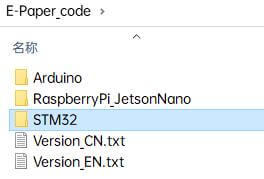
- Use Keil to open epd-demo.uvprojx in the E-Paper_code\STM32\STM32-F103ZET6\MDK-ARM directory
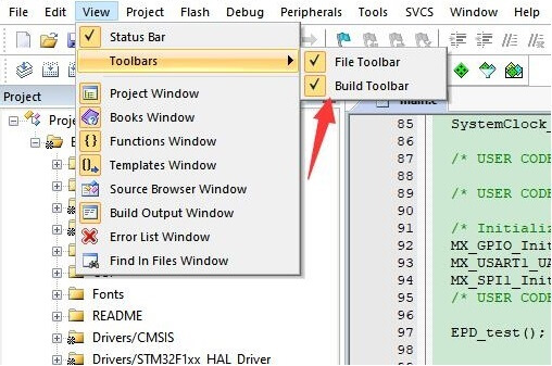
- Open Keil's compilation toolbar (usually already open).
- Select the EPD_7in3f_test at the location shown in the picture.
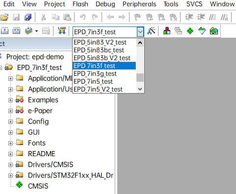
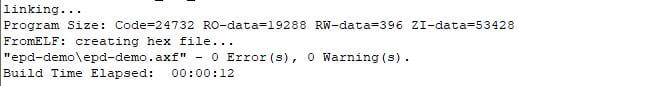
- Click to compile.
- Make sure the appropriate programmer is connected, then click LOAD to download the demo to the microcontroller.