


- sales/support
Google Chat: zj734465502@gmail.com
- sales
+86-0755-88291180
- sales01
sales01@spotpear.com
- sales02
dragon_manager@163.com
- support
services01@spotpear.com
- CEO-Complaints
manager01@spotpear.com
- sales/support
WhatsApp:13246739196
Raspberry Pi SIM7600G-H-M2 4G HAT User Guide
Features
- Supports dial-up, phone call, SMS, TCP, UDP, MQTT, HTTP(S), FTP(S), and so on.
- GNSS positioning: GPS, Beidou, Glonass, Galileo, QZSS, LBS base station.
- USB 3.1 port (USB 2.0 compatible) for connecting to PC, Raspberry Pi, or Jetson Nano host board to enable high speed 4G communication.
- Onboard UART, PWR, and RST control pin, built-in voltage level translator, enabled via DIP switch, for use with hosts like Raspberry Pi or Arduino.
- Onboard USB-C connector, enabled via switch, for connecting standalone power supply for the module, allows more loads, stable amd flexible power supply.
- Onboard power supply on/off switch, reset button and LED indicator, easy to turn on/off the module or monitor the operating status.
- Reserved 4x SMA to IPEX antenna interfaces, with pre-soldered 2x connectors for easily using antennas, allows changing the SMA antenna position.
- Onboard audio jack and audio decoder, allows audio operation like making phone call.
- High efficiency power supply circuit, up to 3A output current.
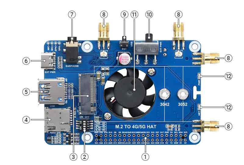
What's On Board
| 标号 | 名称 | 说明 |
|---|---|---|
| ① | Raspberry Pi GPIO interface | Easy connect to Raspberry Pi |
| ② | Switch | Enable the corresponding pin |
| ③ | M.2 interface | Compatible with RM500U-CN / RM500Q-CN / RM500Q-GL /RM50XQ-AE and other series of 5G modules |
| ④ | SIM card holder | Onboard two SIM card slots, dual card single standby.The default SIM1 card slot works, SIM2 is on the back, requires module support, and must be switched through AT commands |
| ⑤ | USB3.1 interface | Backward compatible with USB 2.0, can be used to connect to PC/Raspberry Pi/Jetson Nano etc. |
| ⑥ | USB Type-C interface | 5V 3A input; stable and flexible power supply |
| ⑦ | Audio port | SIM82XX series support audio function, RM50XX series do not support this audio function |
| ⑧ | Antenna interface | Onboard four-way antenna, strong signal |
| ⑨ | Reset Switch | One-key reset |
| ⑩ | Power Switch | To facilitate the power supply mode of the control module: ——If set to USB, the module will provide power through the “⑤.USB3.1 interface”; ——If set to EXT PWR, the module will provide power through the “⑥.USB Type-C interface” external power supply |
| ⑪ | Cooling fan | Cool down the Raspberry Pi and 5G module at the same time |
| ⑫ | Indicator light | Check the module running status anytime, anywhere |
Pinout Definition
After connecting to Raspberry Pi, these pins (TX, RX, D4 and D6) can be connected or not through the DIP switch: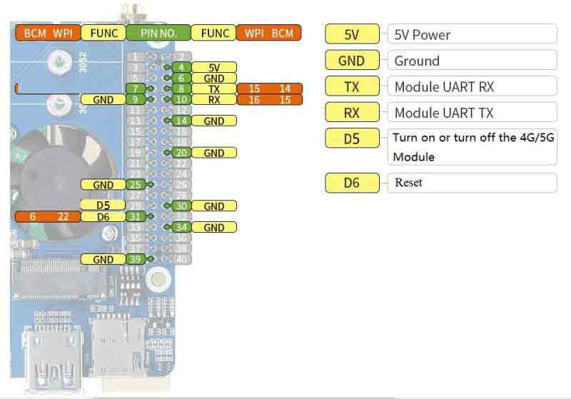
4G/5G modules function testing
| Category | 4G/5G Module | Network Communication | GNSS Positioning | Voice calls through Earphone Port | Dual SIMs | UART Interface | External Power Supply? |
|---|---|---|---|---|---|---|---|
| 5G | SIM8202G-M2 | 5G/4G/3G | Support | Support | Support | Support | Optional, but recommended |
| 5G | SIM8200EA-M2 | 5G/4G/3G | Support | Support | Support | Support | Optional, but recommended |
| 5G | RM500U-CN | 5G/4G/3G | NOT Support | NOT Support | Support | Support | Recommended |
| 5G | RM500Q-GL | 5G/4G/3G | Support | NOT Support | Support | NOT Support | Recommended |
| 5G | RM500Q-AE | 5G/4G/3G | Support | NOT Support | NOT Support | NOT Support | Recommended |
| 5G | RM502Q-AE | 5G/4G/3G | Support | NOT Support | NOT Support | NOT Support | Recommended |
| LTE-A | EM06-E | LTE-A/4G/3G | NOT Support | NOT Support | NOT Support | NOT Support | Optional |
| LTE-A | A7906E | LTE-A/4G/3G | NOT Support | NOT Support | NOT Support | NOT Support | Optional |
| 4G | SIM7600G-H-M2 | 4G/3G/2G | Support | Support | NOT Support | Support | Optional |
4G/5G Module Compatibility
If you need to use the M.2 TO 4G/5G HAT for other 4G/5G modules, you can refer to the M.2 connection diagram below, check whether there is any pin conflict, and then connect to test: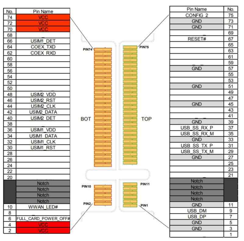
Quick Start
Hardware Preparation
- In addition to the items in the package,
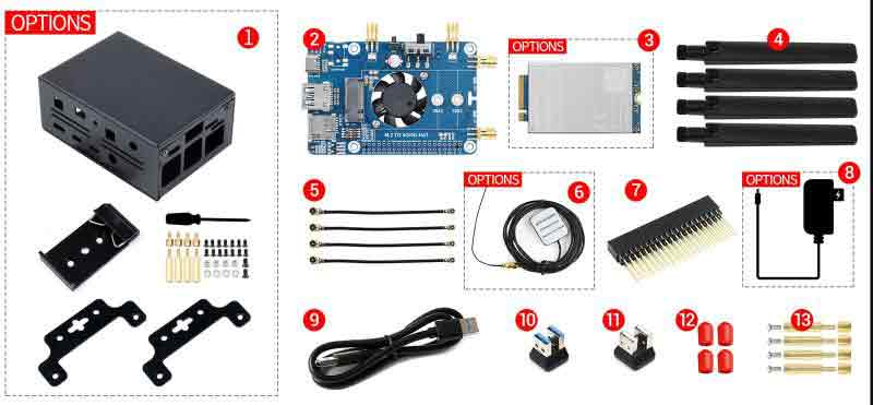
* A 4G SIM card (no downtime and 4G enabled);
* A computer with a Windows operating system (Such as Windows 10)
* A USB TO UART module (optional)
* A headphone cable with a microphone (optional);
Test
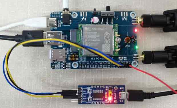
- In the case of power off, insert the activated 4G SIM card, the headphone cable with microphone (optional), and then connect the USB cable to the computer.
- Connect one end of the micro USB cable to the USB interface of the PC, and the other end to the USB interface of the SIM7600G-H-M2 4G HAT, the PWR light is on, and the NET light is off.
- When you see the NET light starts flashing every second, the module starts to work.
- Turn the TX and RX of the DIP switch to the ON side, connect to the computer and other equipment through the USB TO UART module, and perform AT command to debug on the corresponding COM port. (optional)
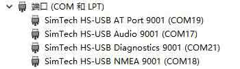
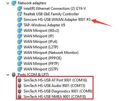
- Open the device manager and you can see that there are COM ports as shown in the figure below.
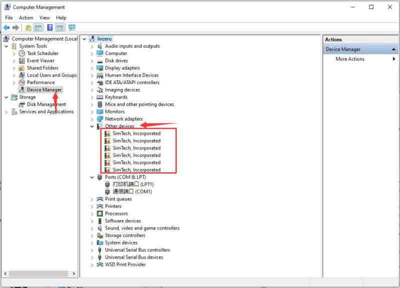
- If the COM port is recognized in the above picture, but an exclamation mark appears, it means that the driver has not been installed, and can be manually loaded as follows:
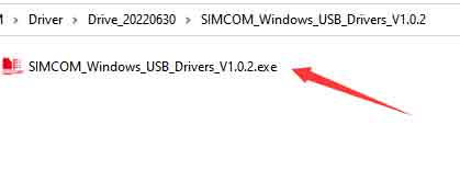
- Download drive: SIM7600X drive document.
- Insert the USB port of the 4G HAT into a Windows computer (the Windows 10 operating system is used as an example below)
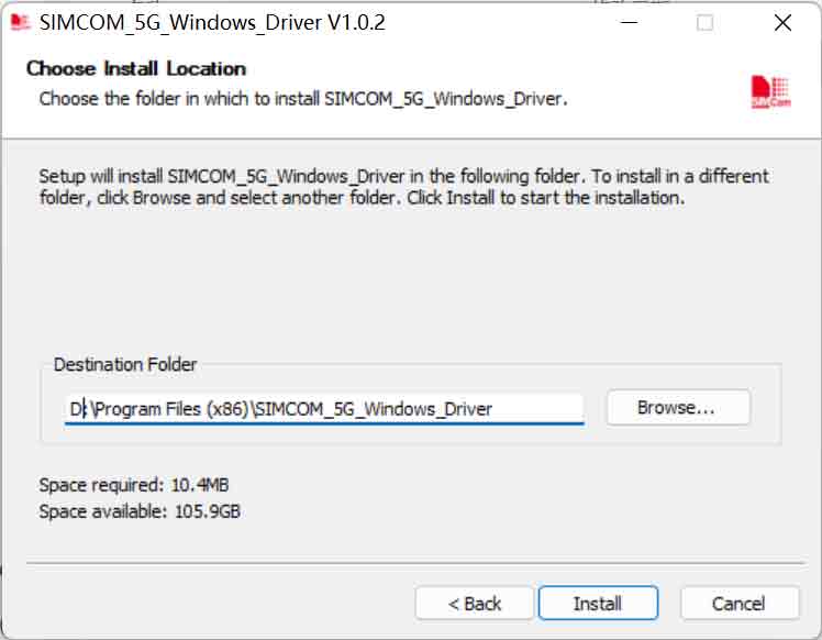
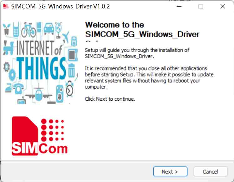
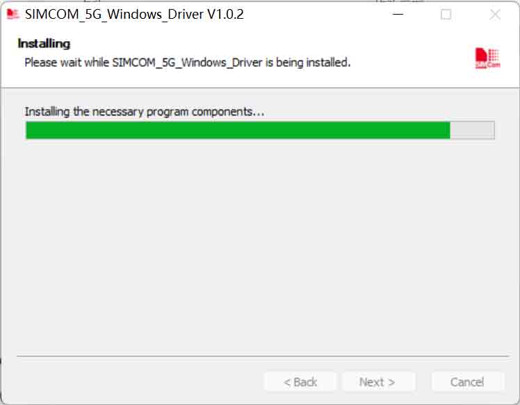
- Unzip the driver file --> Double-click the exe driver file with the left mouse button --> Select the installation path --> NEXT --> Wait for the installation to complete --> Restart the computer --> Complete the driver installation.
- After installation, all the devices should be recognized normally as below:
Net light operating condition
Net light operating condition as follows:
| Net Light working mode | Module working mode |
|---|---|
| Always on | searching for the net or on the call |
| 200ms on/200ms off | Data connection established |
| 800ms on/800ms off | the network is registered |
| Off | Shutdown or hibernate mode |
Brief description of the test
Common AT commands
| Command | Description | Return Value |
|---|---|---|
| AT | AT test command | OK |
| ATE | ATE1 sets echo ATE0 turns off echo | OK |
| AT+CGMI | Query module manufacture | OK |
| AT+CGMM | Query module model | OK |
| AT+CGSN | Query product serial number | OK |
| AT+CSUB | Query module version and chip | OK |
| AT+CGMR | Query the firmware version serial number | OK |
| AT+IPREX | Set the module hardware serial port baud rate | +IPREX: OK |
| AT+CRESET | reset module | OK |
| AT+CSQ | Network signal quality query, return signal value | +CSQ: 17,99 OK |
| AT+CPIN? | Query the status of the SIM card and return READY, indicating that the SIM card can be recognized normally | +CPIN: READY |
| AT+COPS? | Query the current operator, the operator information will be returned after normal networking | +COPS: OK |
| AT+CREG? | Query network registration status | +CREG: OK |
| AT+CPSI? | Query UE system information | |
| AT+CNMP | Network mode selection command: 2:Automatic 13:GSM only 38:LTE only 48 : Any modes but LTE ... .... | OK |
For more AT commands, see SIM7500_SIM7600 Series_AT Command manual_v1.07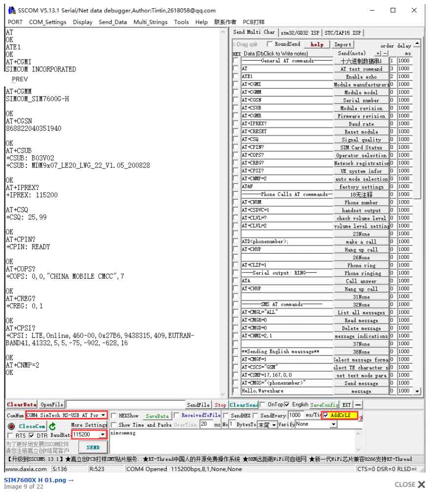
Use in Windows
Dail-up
[Note]: You must use a SIM card with GPRS networking function enabled and not out of service.
NDIS Dail-up
- At present, when using Windows 10 operating system, you can connect to 4G DONGLE module (equipped with 4G card of China Mobile/Telecom/Unicom). After installing the driver, most computers will automatically connect to the Internet.
- If WINdows cannot access the Internet, you need to manually start NDIS dialing, open SIM7600 AT port, and send the command:
AT$QCRMCALL=1,1+enter
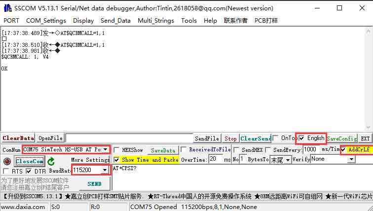
At this point, the NDIS dialing takes effect, and the computer can connect to the network; if the dialing command returns an error, send the following command to set the NDIS dialing mode and then dial again:
AT+CUSBPIDSWITCH=9001,1,1
RNDIS Dial-Up Internet
In addition, dial-up Internet access using RNDIS is also possible:
- After the device installed SIM card and antenna, connect the USB port to computer, then connect the power supply.
- Refer to the above to install the USB driver
- Open the serial port assistant, find the serial port number corresponding to the AT serial port, and send the AT command to check whether it is registered on the network:
AT+CPSI?
- If you have successfully registered on the network, then send the AT command to enable USB dial-up Internet access:
AT+CUSBPIDSWITCH=9011,1,1
- If the transmission is successful, the DTU will return OK and reboot automatically.
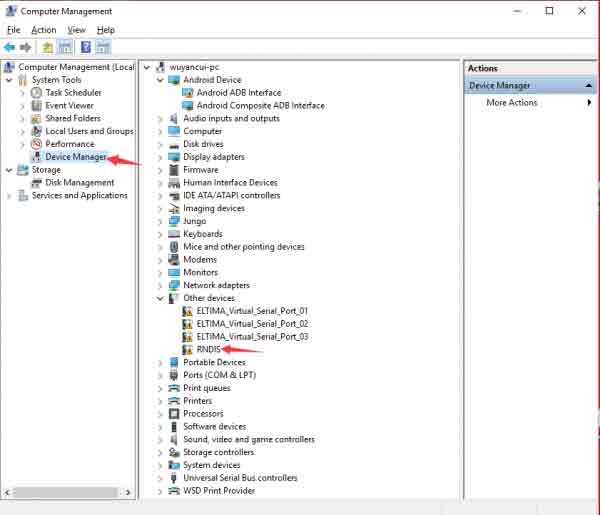
- And then you can find that there are some unrecognized devices in the Device Manager on the computer, such as RNDIS (with exclamation mark).
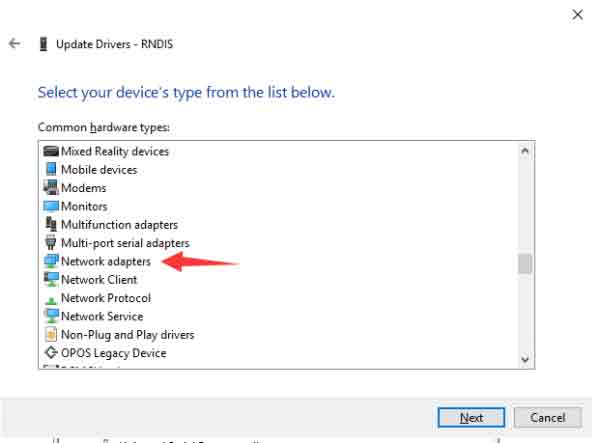
- Right-click the 'RNDIS', search "Update Divers" and select "Let me pick from a list of available drivers on my computer", then select "Network adapters" from the device list.
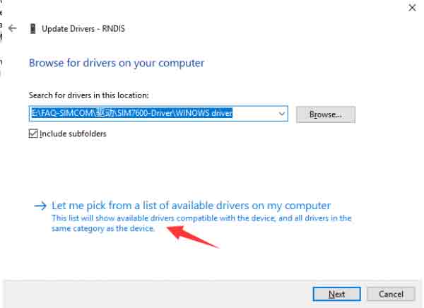
- Select "Microsoft" in the manufacturer list of the Network adapters window, and then select "Remote NDIS Compatible Device" in the list on the right, which is the remote NDIS compatible device.
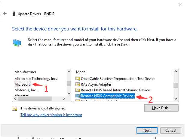
Click 'Next' and wait for the installation to finish, the RNDIS Kitl device will be installed successfully. And then you can see that the PC can access the Internet via DTU.
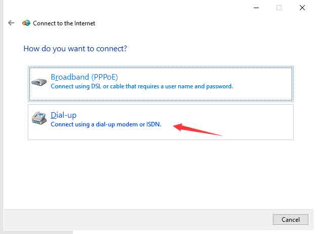
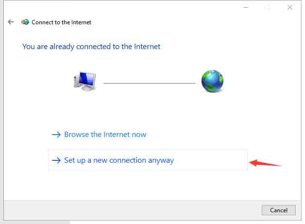
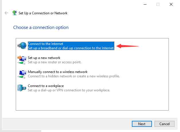
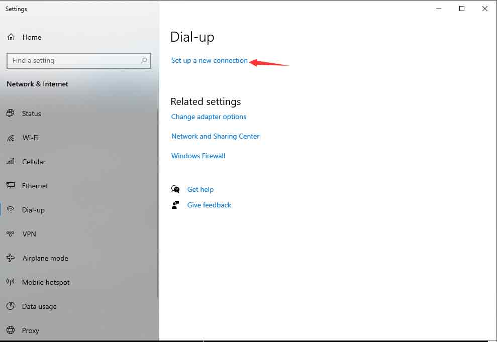
PPP dial-up
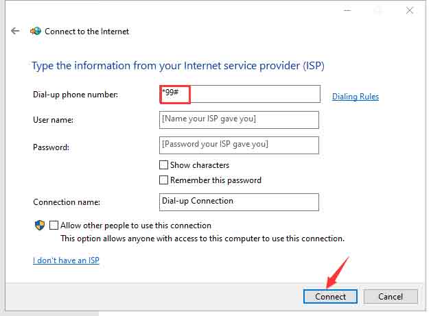
If the NDIS or RNDIS dial-up cannot access the Internet, you can also use PPP dial-up. The operation steps are as follows:
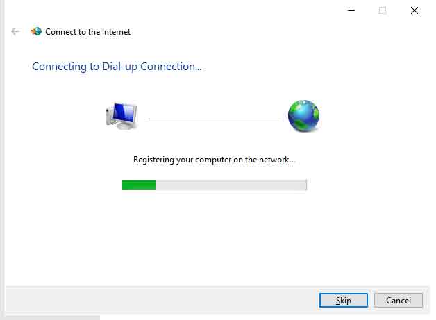
- Network and Internet Settings -> Set up a new connection -> Connect to the Internet -> Dial up (D) -> Dial a phone number (D): *99# (others are empty by default) -> Connection -> Register -> Connected to the Internet
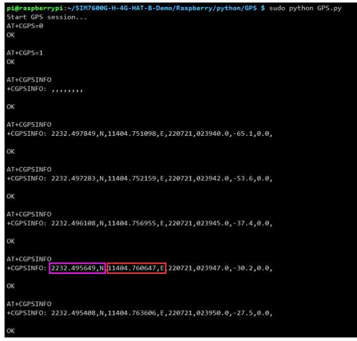
GPS Test
GNSS control instance
- Plug in the GPS antenna, and place the receiver tag face down in the open air,(Note that rainy weather cannot be tested) you need to wait about 1 minute before receiving the location signal.
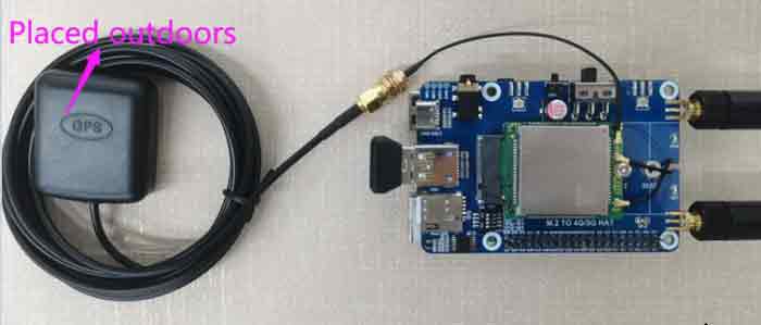
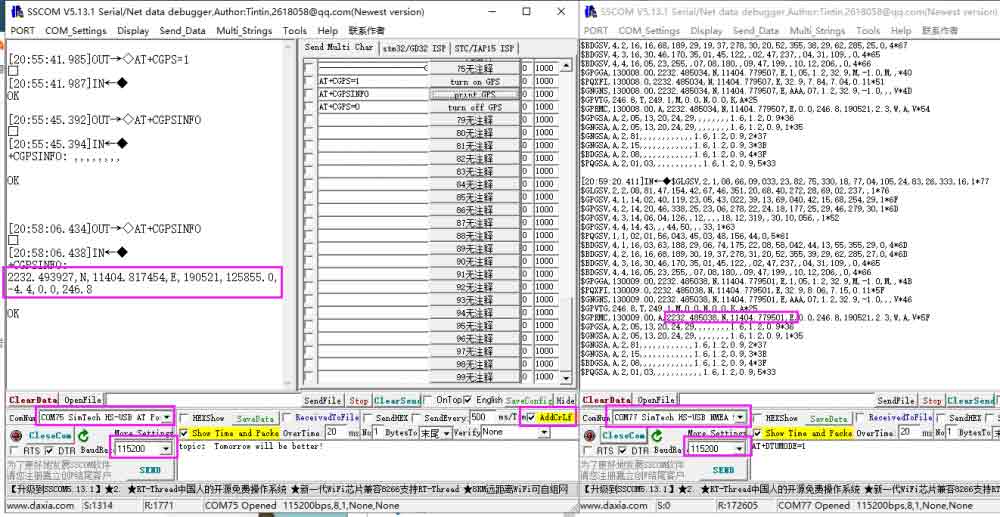
- Detailed test instructions and screenshots are as follows:
AT+CGPS=1               // Open GPS
AT+CGPSINFO             // Prints GPS information to the serial port
AT+CGPS=0               // Turn off GPS
TCP/IP Internet data
GPRS debugging requires a SIM card with GPRS networking function enabled:
The following example takes accessing a mobile SIM card as an example:
- Correctly install the mobile phone card (the GPRS networking function must be enabled), the GSM antenna, and connect the USB cable to the computer;
- Press the PWR key to start the module and wait for more than ten seconds;
- Observe whether the indicator light is normal, the PWR indicator is always on, and the NET indicator is flashing;
Set up a local computer virtual server
The virtual server defines the mapping relationship between the WAN service port and the LAN network server. All access to the WAN service port will be relocated to the LAN network server specified by the IP address. (Please refer to your router's corresponding manufacturer's manual)
- Use a browser to log in to the router management interface (please refer to your router manual for the specific address)
- Set the port number: 2317 (it does not conflict with the existing port number. In this example, it is set to 2317)
- Set the intranet IP of the computer (the IP obtained by the computer in the local area network can be run CMD on the local machine, enter the command line prompt, enter ipconfig to check the IPv4 address, the intranet IP of the computer in this example is 192.168.1.168), as shown in the following figure :

Configure GPRS
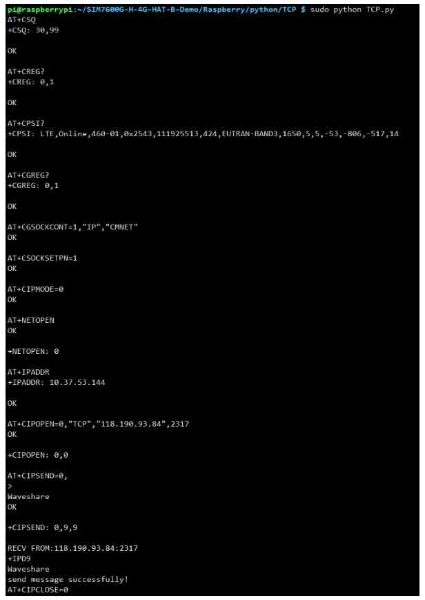
AT+CGDCONT=1,"IP","CMNET"     //Set APN
AT+CSQ       //Query the network signal quality. The first parameter is that the network signal quality is up to 31. The larger the  value, the stronger the network signal.
AT+CREG?         //Query the network registration status, where the second parameter is 1, indicating that the registration has    been successful.
AT+CIPMODE=1        //Set TCP/IP mode
AT+CSOCKSETPN=1          //select TCP/IP application mode
AT+CIPMODE=0          //select TCP/IP application mode
AT+NETOPEN         //startup mode
AT+CIPOPEN=0,"TCP","113.81.233.65",2317         //Set TCP、IP and port number, establish TCP/IP connection
AT+CIPSEND=0,9,         //To specify to send 9 characters of data, return to > to start sending 9 characters of content
AT+CIPCLOSE=0,         //close the TCP connection
AT+NETCLOSE,         //close the network
The operation is shown in the following figure: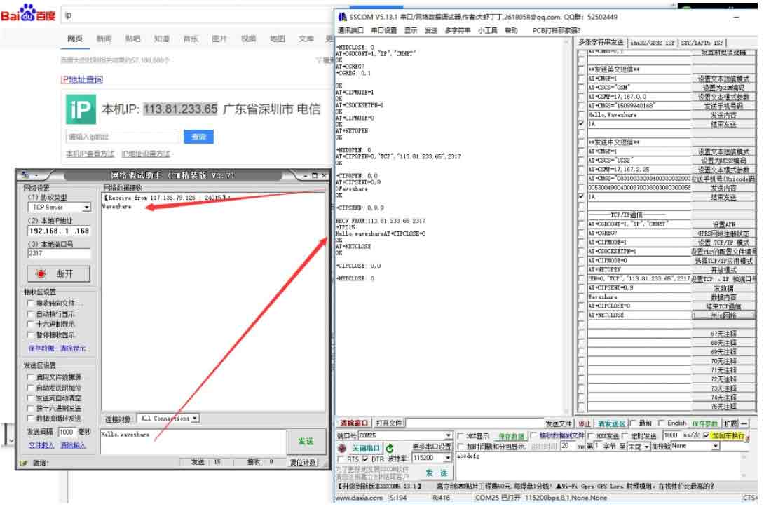
Call Phone
- Refer to the "Hardware Configuration" chapter to connect the LTE antenna, SIM card (the phone function must be enabled) and the headset cable with microphone, and the module is turned on.
- Common commands for making calls:
| AT+CNUM | Check the phone number (not all SIM cards support this command) | +CNUM OK |
|---|---|---|
| AT+CSDVC | AT+CSDVC=1: switch to headphone output AT+CSDVC=3: switch to speaker output | OK |
| AT+CLVL=? | Query volume range | OK |
| AT+CLVL=2 | set volume to 2 | OK |
| ATD<phone_number>; | ATD10086; Dial Mobile customer service phone number 10086 | OK |
| AT+CHUP | set volume to 2 | OK |
| AT+CLIP=1 | Set up caller ID | OK |
| ATA | Answering the Phone | OK |
- The detailed operation screenshots are as follows:
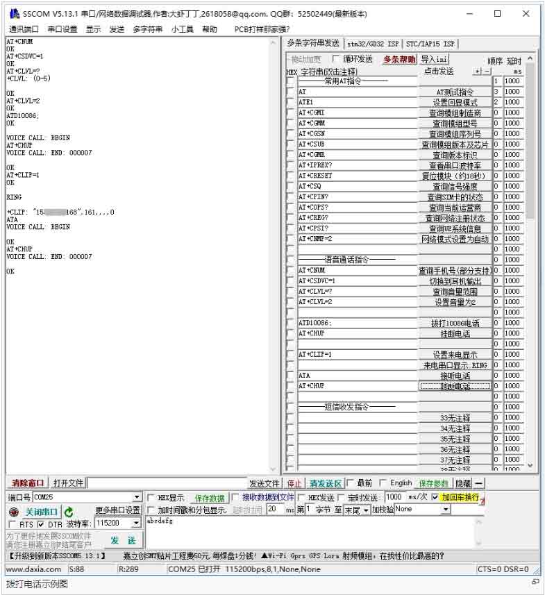
[Note]: When using the SSCOM serial port assistant to send and receive AT commands, you must click "carriage return and line feed"
Voice output mode and volume adjustment
AT+CSDVC=1 		//switch to headphones
AT+CSDVC =3 	        //switch to speaker
AT+CLVL =?		//Query the volume range, return +CLVL: (0-5) //Indicates that the volume is adjustable from 0 to 5
AT+CLVL=2     	        //Set the volume to 2, return OK
Answer the phone
Incoming call serial port display: RING
Send “ATA”      //Answer the phone
Send ”AT+CHUP”  //Hang up
Audio parameter debugging
AT+CACDBFN=?
+CACDBFN: (Handset_cal.acdb,Handset_tianmai.acdb)	// It is recommended to consider setting this set of parameters
OK
A.In the initialization stage of the module startup, before making a call, add the following
AT^PWRCTL=0,1,3	// Mainly improve TDD noise effect
OK
B. The module is in the process of establishing a voice call
VOICE CALL:BEGIN  	// Establish module call to improve call    effect
AT+CECM=1      		//suppress echo
OK
AT+CECH=0x500 	// improve the volume on the mobile phone
OK
See "SIM7X00_Audio_Application_Note" document for details
Send English SMS
- Correctly install the SIM card and LTE antenna, connect the module's USB interface to the computer with a USB cable, and turn on the module;
- Observe whether the indicator light is normal, the PWR indicator is always on, and the NET indicator is flashing;
- Set the local SMS center: AT + CSCA = " + 8613800755500" + Enter, return OK.
Note: China Mobile's SMS service center number is +861380xxxx500, where xxxx is the long-distance telephone area code where you are located. The SMS center may be different from place to place. For details, you can query Baidu or call China Mobile Unicom customer service. This SMS center is Shenzhen (0755) ;
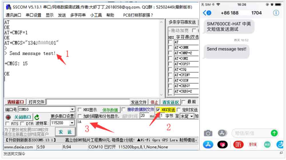
- AT+CMGF=1: Set the SMS mode to TEXT;
- AT+CMGS="phone number"<Enter>, set the recipient's phone number, and then return: ">", send the content what you need, such as "Send massage test!", You don’t need to “Enter” at the end. After editing the text message, send 1A to send information in hexadecimal format (1A is the key value of "CTRL+Z", which is used to tell the module to perform the sending operation, or 1B or "ESC" to cancel the operation). After successfully sending, the module returns + CMGS: 15 confirm that the transmission was successful. As shown below.
Receive English SMS
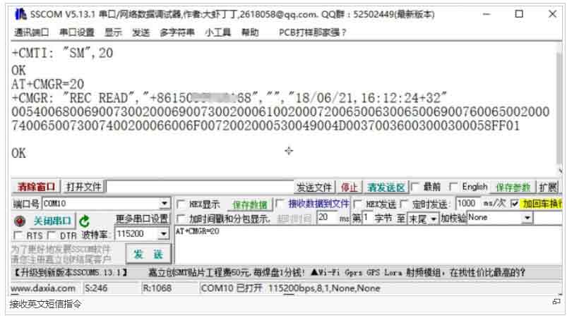
- Send a message on the phone: "This is a receive test for SIM7600X!" to the test module
- When receiving the information, the serial port will brake and report the information, "SM", 20, which means there are 20 pieces of information in the SM, and the message just sent is the 20th piece of information.
- Read information: AT+CMGR=20 to read the 20th information (AT+CMGL="ALL" to read all information)
- Delete information: AT+CMGD=20, as shown below
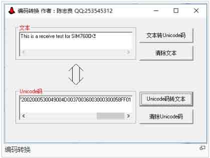
- Convert the displayed information to text through a code converter.
Send Chinese SMS
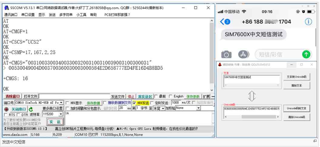
- Set the parameters for sending SMS
AT+CMGF=1             //set to text mode
AT+CSCS="UCS2"           //Set info text to UCS2 encoding set
AT+CSMP=17,167,2,25          //Set text mode parameters
AT+CMGS="00310033003400330032003100310039003100300031"          //Set the UCS2 set of the receiver's mobile number
- Waiting to return >, send the information content converted by the software at this time (00530049004D003700360030003000584E2D658777ED4FE16D4B8BD5), no carriage return is required at the end, after editing the text message, send 1A to send the message in hexadecimal format, as shown in the following figure:
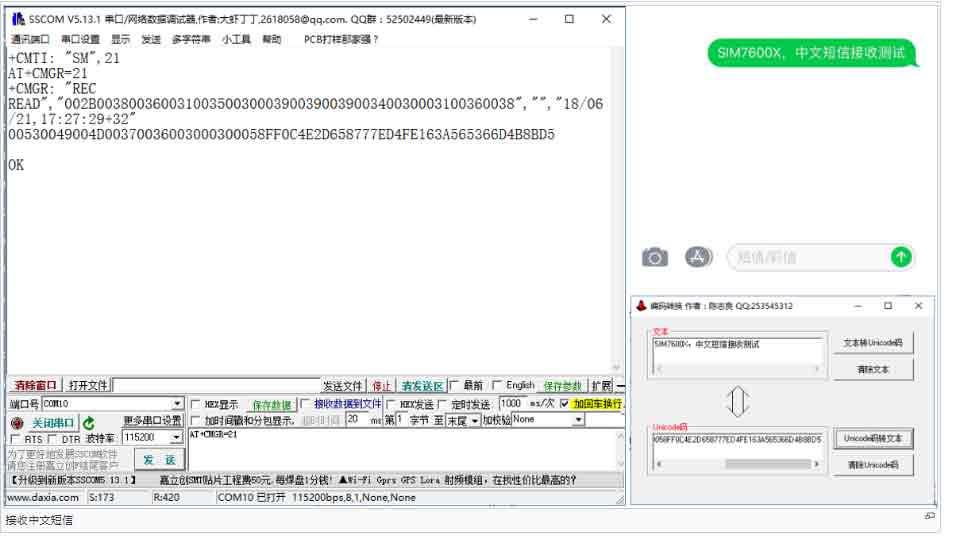
Receive Chinese SMS
- Set the parameters for sending SMS
AT+CMGF=1    	 //set test mode
AT+CSCS="GSM"	//set GSM code set
AT+CNMI=2,1   	//Set up new message alerts
- When receiving the information, the serial port will automatically report the information, and read the returned 21st information as shown in the figure below:
AT+CMGR=21 //Read the SMS content of serial number 21
- Translate the information into Chinese in the software, as shown below:
User Guides of Raspberry Pi
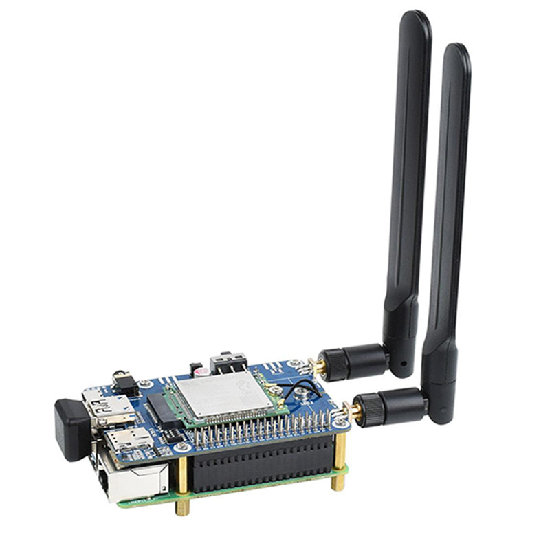
Hardware Connection
Connect the 5G HAT with a double-ended usb3.0 data cable, and connect an external 5V power supply to the Type-C power supply port of the 5G HAT, as shown in the figure: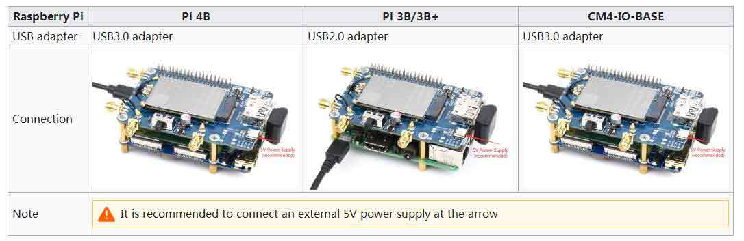
If it is used for PI4B, there is a matching case, and the installation diagram is as follows:

Raspberry Pi Internet Operation
If you are using Raspberry Pi 4B, Raspberry Pi 3B+ or CM4-IO-BASE-A/B baseboard, you can use the used the customized USB adapter.if it is used for other embedded mainboards or PCs, it can be connected through the matching double-head usb3.0 data cable; as shown in the following figure: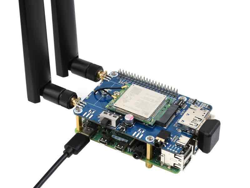
For specific operations related to Raspberry Pi dial-up Internet access, please refer to the following links:
- Raspberry Pi RNDIS dial-up Internet- (the easiest way to operate)
- Raspberry Pi PPP dial-up- (the operation is relatively simple)
- Raspberry Pi NDIS dial-up Internet access
Raspberry Pi Minicom Sends AT Command to Debug
1. Connect the module into Raspberry Pi
2. Install minicom, minicom is a serial debugging tool for linux platform
sudo apt-get install minicom
3. USB and UART serial AT command debugging
- Execute minicom -D /dev/ttyUSB2. (default baud rate is 115200)
sudo minicom -D /dev/ttyUSB2
- Enter the following AT command in minicom to open the UART. (default baud rate is 115200)
AT+CCUART=1
- Turn ON the TXD and RXD of the dial switch and execute minicom -D /dev/ttyS0. (Baud rate 115200)
sudo minicom -D /dev/ttyS0 -b 115200
4. Taking the AT synchronization test as an example, send relevant commands, as shown in the following figure:
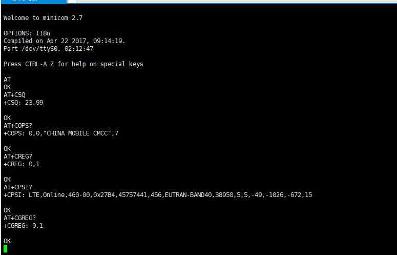
* minicom can enter the setting mode by pressing Ctrl+A, then Z, and exit by selecting X. If the sending command does not display, please send the command ATE=1 + Enter -> open the echo
Program sample
- After inserting the module and connecting it to the Raspberry Pi;
- Download the sample program to the /home/pi/ path;
wget https://www.waveshare.net/w/upload/5/5c/SIM7600G-H-4G-HAT-B-Demo.zip
sudo apt-get install p7zip-full
7z x SIM7600G-H-4G-HAT-B-Demo.zip
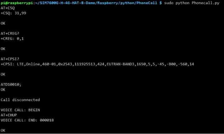
3. Go to the corresponding instance directory, compile and run the program, the relevant instructions are as follows (take the PhoneCall.py program as an example):
cd SIM7600G-H-4G-HAT-B-Demo/Raspberry/python/PhoneCall/ //Enter the folder where PhoneCall.py is located
sudo apt-get install python3-pip
sudo pip3 install pyserial
sudo pip3 install RPi.GPIO
sudo python PhoneCall.py //Run the program
5G HAT Power or Reset Control
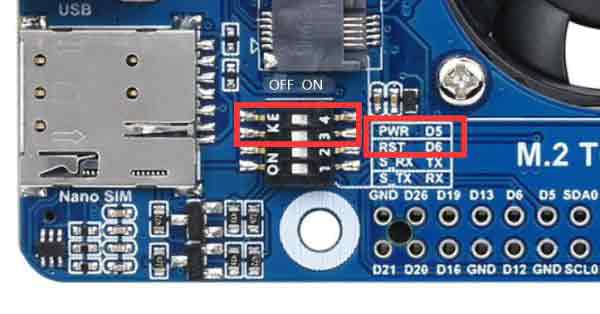
The 5G HAT is provided with PWR and RESET control pins, and the Raspberry Pi can control the module power on/off or reset through the high and low levels of these two pins.
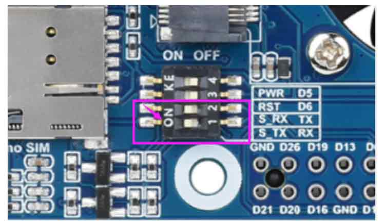
- Turn the PWR and RST setting switches to
the rightto enable Pi control:
- Power Control:The following demonstrates the Shell script to control the PWR (D5 PIN) as an example:
cd /sys/class/gpio
echo 5 > export

cd gpio5
echo out > direction
echo 1 > value    #set to high level to shut down the 5G module
echo 0 > value    #set to low level to power on the 5G module
echo 5 > unexport- Reset Control:The following demonstrates the Shell script to control the Reset (D6 PIN) as an example:
cd /sys/class/gpio
echo 6 > export

cd gpio6
echo out > direction
echo 1 > value    #set to high level to shut down the 5G module
sleep 1           #wait for 1 second
echo 0 > value    #set to low level to power on the 5G module
echo 5 > unexport
AT Command
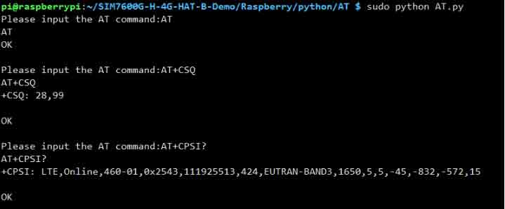
Phone Call Demo
Receive & Send SMS
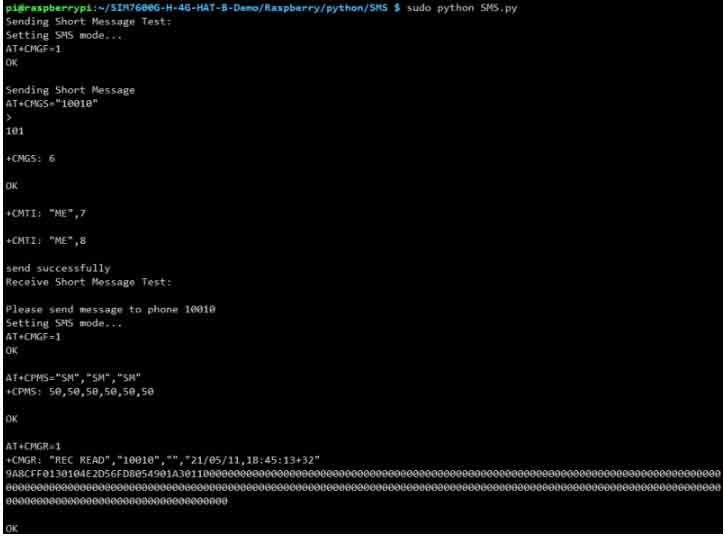
Note: The sample program is to send English text messages. If you have sent Chinese text messages, you need to use the following commands to change to English format:
AT+CSMP=17,167,0,240
GPS Demo
TCP Network Communication Demo
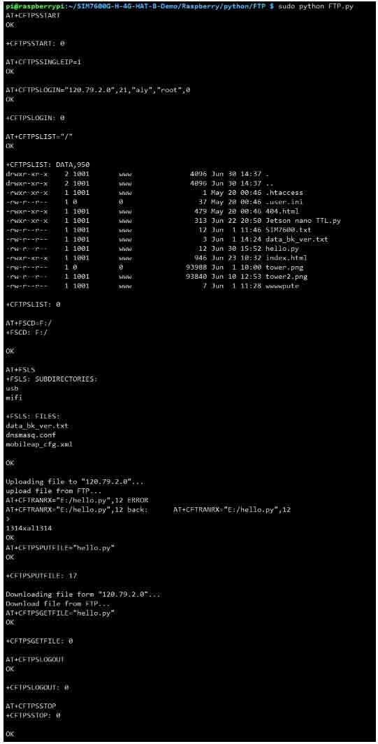
FTP Upload & Download Demo
Jetson Nano Demo
Hardware Connection
Jetson Nano has an onboard USB interface, SIM7600X 4G HAT(B) is connected to the USB interface of Jetson Nano through Micro USB.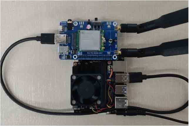
Jetson Nano minicom Serial Port Debugging
1. Connect the SIM7600X 4G HAT(B) to the Jetson Nano and turn it on after three seconds
2. Use Template:SERIAL to log in to the Jetson Nano terminal, install minicom, and enter:
sudo apt-get install minicom
3. Run minicom for debugging, and enter in the terminal
sudo minicom -D /dev/ttyUSB2 -b 115200
4. Send AT command to test, exit minicom and press Ctrl+A, then X, and finally press ENTER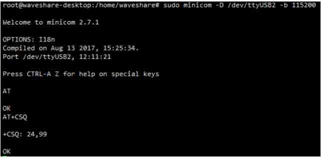
More demos to be continued...


.png)