


- sales/support
Google Chat: zj734465502@gmail.com
- sales
+86-0755-88291180
- sales01
sales01@spotpear.com
- sales02
dragon_manager@163.com
- support
services01@spotpear.com
- CEO-Complaints
manager01@spotpear.com
- sales/support
WhatsApp:13246739196
Raspberry Pi Pico RP2040-LCD-1.28 User Guide
Resource
Demo
- Demo code
- LVGL Demo code
- Clock project shared by Wienzek Daniel
- Demo codes based on PlatformIO, shared by Philipp Molitor
Drawing
Datasheet
Official Raspberry Pi Documents
- Raspberry Pi Pico MicroPython Book
- Raspberry Pi related books
- Pico datasheet
- RPI-PICO-R3-PUBLIC-SCHEMATIC
- Pico R3 A4 Pinout
- Getting started with pico
- Pico c sdk
- Pico python sdk.pdf
- Pico datasheet
- Rp2040 datasheet
- Hardware design with rp2040
Raspberry Pi Demo
Development Software
Pico Quick Start
Download Firmware
- MicroPython Firmware Download
- C_Blink Firmware Download
Video Tutorial
- Pico Tutorial I - Basic Introduction
- Pico Tutorial II - GPIO
- Pico Tutorial III - PWM
- Pico Tutorial IV - ADC
- Pico Tutorial V - UART
- Pico Tutorial VI - To be continued...
MicroPython Series
- 【MicroPython】 machine.Pin Function
- 【MicroPython】 machine.PWM Function
- 【MicroPython】 machine.ADC Function
- 【MicroPython】 machine.UART Function
- 【MicroPython】 machine.I2C Function
- 【MicroPython】 machine.SPI Function
- 【MicroPython】 rp2.StateMachine
C/C++ Series
Arduino IDE Series
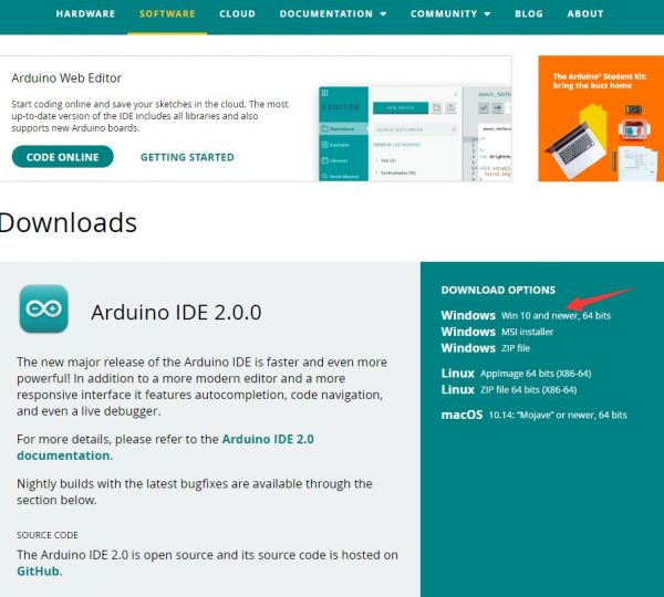
Install Arduino IDE
- Download the Arduino IDE installation package from Arduino website.
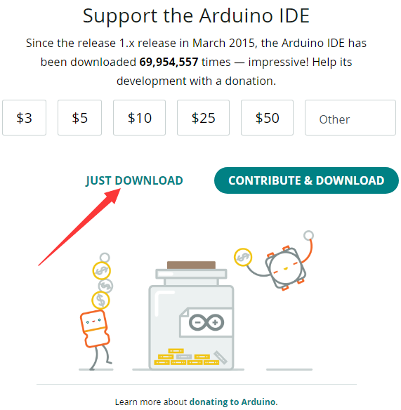
- Just click on "JUST DOWNLOAD".
- Click to install after downloading.
- Note: You will be prompted to install the driver during the installation process, we can click Install.
Install Arduino-Pico Core on Arduino IDE
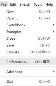
- Open Arduino IDE, click the File on the left corner and choose "Preferences".
- Add the following link in the additional development board manager URL, then click OK.
https://github.com/earlephilhower/arduino-pico/releases/download/global/package_rp2040_index.json
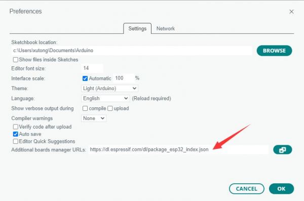
Note: If you already have the ESP8266 board URL, you can separate the URLs with commas like this:https://dl.espressif.com/dl/package_esp32_index.json,https://github.com/earlephilhower/arduino-pico/releases/download/global/package_rp2040_index.json
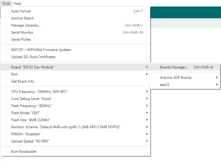
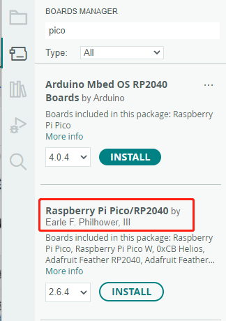
- Click on Tools -> Dev Board -> Dev Board Manager -> Search for pico, it shows installed since my computer has already installed it.
Upload Demo At the First Time
- Press and hold the BOOTSET button on the Pico board, connect the Pico to the USB port of the computer via the Micro USB cable, and release the button when the computer recognizes a removable hard drive (RPI-RP2).
- Download the demo, open arduino\PWM\D1-LED path under the D1-LED.ino.
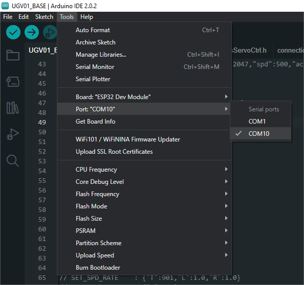
- Click Tools -> Port, remember the existing COM, do not need to click this COM (different computers show different COM, remember the existing COM on your computer).
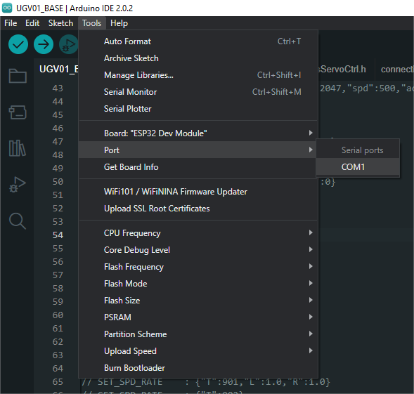
- Connect the driver board to the computer with a USB cable, then click Tools -> Ports, select uf2 Board for the first connection, and after the upload is complete, connecting again will result in an additional COM port.
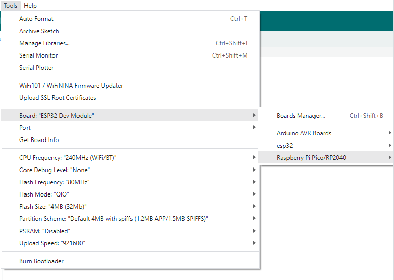
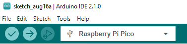
- Click Tool -> Dev Board -> Raspberry Pi Pico/RP2040 -> Raspberry Pi Pico.
- After setting, click the right arrow to upload.
- If you encounter problems during the period, you need to reinstall or replace the Arduino IDE version, uninstall the Arduino IDE needs to be uninstalled cleanly, after uninstalling the software you need to manually delete all the contents of the folder C:\Users\[name]\AppData\Local\Arduino15 (you need to show the hidden files in order to see it) and then reinstall.
Open Source Demo
- MicroPython Demo (GitHub)
- MicroPython Firmware/Blink Demo (C)
- Official Raspberry Pi C/C++ Demo
- Official Raspberry Pi MicroPython Demo
- Arduino Official C/C++ Demo
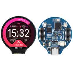
Overview
RP2040-LCD-1.28 is a low-cost, high-performance MCU board designed by Waveshare. Although it is tiny, it incorporates a 1.28inch LCD round display, Li-ion battery charger, 6-axis sensor (3-axis accelerometer and 3-axis gyroscope) and so on, adapting all GPIO and Debug headers, which makes it easy for you to develop and integrate it into products quickly.
Feature
- RP2040 MCU chip designed by Raspberry Pi in the United Kingdom
- Dual-core Arm Cortex M0+ processor, flexible clock running up to 133 MHz
- 264KB of SRAM, and 2MB of onboard Flash memory
- Type-C connector, keeps it up to date, easier to use
- Onboard 1.28-inch 240 x 240 resolution, 65K RGB IPS LCD display for clear color pictures
- Lithium battery recharge/discharge header, suitable for mobile devices
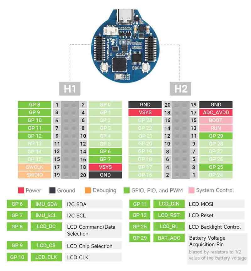
- All GPIOs are adapted through 1.27 pitch female headers (There are 30 pins in total, but some pins have been connected to the internal circuit, you need to pay attention when multiplexing, please refer to the wiki for details)
- USB 1.1 with device and host support
- Low-power sleep and dormant modes
- Drag-and-drop programming using mass storage over USB
- 2 x SPI, 2 x I2C, 2 x UART, 2 x UART, 4 x 12-bit ADC, 16 × controllable PWM channels
- Accurate clock and timer on-chip
- Temperature sensor
- Accelerated floating-point libraries on-chip
- 8 x Programmable I/O (PIO) state machines for custom peripheral support
Specification
| LCD Parameter | |||
| Controller | GC9A01A | Resolution | 240 (H) RGB x 240(V) |
| Communication interface | SPI | Display Size | Φ32.4mm |
| Display Panel | IPS | Pixel Size | 0.135 (H) x 0.135 (V) mm |
| IMU Parameter | |||
| Sensor | QMI8658C | ||
| Accelerometer | Resolution: 16 bits Measurement Range (optional): ±2, ±4, ±8, ±16g | ||
| Gyroscope | Resolution: 16 bits Measurement Range (optional): ±16, ±32, ±64, ±128, ±256, ±512, ±1024, ±2048°/sec | ||
Pinout
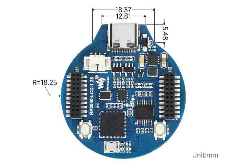
Dimensions
Example Demo
LVGL Example Demo
Example Effect
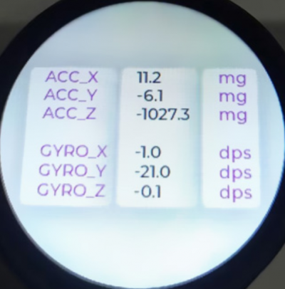
The demonstration displays two interfaces that can be switched by either sliding on the touchscreen or tilting with the six-axis sensor.
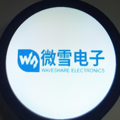
- The first interface:
- The second interface
Example
This example is for testing LVGL control interaction, styling, etc. For details, you can refer to LVGL development document.
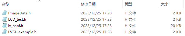
Source Code Structure
- The source code of the LVGL library is in ./lib/lvgl, and the version is 8.1. For the secondary development, you can refer to the development document.
- The related setting of the LVGL library is in ./examples/inc/lv_conf.h, and you can set the display refreshing rate, the system occupied data, and so on.
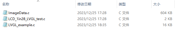
- The application code of the LVGL library is in ./examples/src/LVGL_example.c.
Functions
- This example utilizes DMA for transferring color data to the SPI bus, reducing CPU utilization. The CPU usage remains below 20% during simple interactions, and memory usage stays below 30%.
- The system clock in this example runs at 270MHz. The peripheral clock frequency of the SPI is set to match the system clock. Additionally, the LVGL library's double buffering mechanism is employed, ensuring smooth animations by rendering one buffer while transferring data in the other.
- A six-axis simulator is used in this example, emulating gyroscope data as input for encoder devices, which can be applied in various interactive scenarios.
Compile to run
- Enter the source code directory. If the build exists, you can directly enter. If not, execute:
mkdir build
- Enter build directory and add the SDK address:
cd build
export PICO_SDK_PATH=../../pico-sdk
Note: the path of pico-sdk needs to be adjusted by the reality.
- Execute cmake, the Makefile file automatically generates:
cmake ..
- Execute make to generate the executable file, and input it in the terminal:
make
Just wait for the compilation to be done and copy the resulting file in .uf2 format to pico.
Source Code Explanation
LVGL Initialization
- Initialization function:
- FunctionL For initializing all the hardware and structure variables required for LVGL.
void LVGL_Init(void);
- LVGL Library Core Structure Variable Definition
- Definition Function: The initialization process of the LVGL library mainly involves initializing several core structure variables of LVGL. The operation of the LVGL library relies on these core structure variables.
- Definition Method: Setting the sizes of buf0 and buf1 to half the screen display area is aimed at implementing the LVGL double buffering mechanism. This mechanism helps reduce noticeable jagged edges during extensive screen redraws while effectively enhancing the screen refresh rate. When using a single buffer, it's preferable to set it to 10% of the screen display area to significantly reduce system occupancy. However, this setup may result in more apparent jagged edges during extensive image refreshes.
// LVGL
static lv_disp_draw_buf_t disp_buf;                   //LVGL display buffer
static lv_color_t buf0[DISP_HOR_RES * DISP_VER_RES/2];//LVGL color data buffer 0
static lv_color_t buf1[DISP_HOR_RES * DISP_VER_RES/2];//LVGL color data buffer 1
static lv_disp_drv_t disp_drv;                        //LVGL display driver

static lv_indev_drv_t indev_en;                       //LVGL 6-axis sensor analog encoder input device driver
static lv_group_t *group;                             //Encoder control group
- How to realize the initialization of the LVGL library
- Function: improve the core structure variables of the LVGL library.
- Method: The encoder input device of the LVGL library has both an edit mode and a browse mode. In the browse mode, triggering a switch event will change the selected control within the control group. Triggering a confirmation event will transition the selected control into edit mode. Therefore, when simulating an encoder with a six-axis sensor, it's essential to introduce the 'lv_group_t' structure variable as the control group for the six-axis sensor.
// Initialize LVGL core
lv_init();

// Initialize the LVGL display buffer structure variable disp_buf
lv_disp_draw_buf_init(&disp_buf, buf0, buf1, DISP_HOR_RES * DISP_VER_RES / 2);
lv_disp_drv_init(&disp_drv);
disp_drv.flush_cb = disp_flush_cb;
disp_drv.draw_buf = &disp_buf;
disp_drv.hor_res = DISP_HOR_RES;
disp_drv.ver_res = DISP_VER_RES;
lv_disp_t *disp= lv_disp_drv_register(&disp_drv);

// Initialize the encoder input device
lv_indev_drv_init(&indev_en);
indev_en.type = LV_INDEV_TYPE_ENCODER;
indev_en.read_cb = encoder_read_cb;
lv_indev_t * encoder_indev = lv_indev_drv_register(&indev_en);
group = lv_group_create();
lv_indev_set_group(encoder_indev, group);//Adding encoder control devices to a control group
- Run the LVGL library
- Function: The LVGL library calls the function lv_tick_inc periodically to inform LVGL about the passage of time. This allows LVGL to update its internal time status and handle time-related tasks such as animations and timers. Additionally, within the main function loop, the lv_task_handler function needs to be called to manage predefined tasks.
- Implementation method: It's crucial to ensure that the priority of lv_task_handler is lower than that of lv_tick_inc. Therefore, in this example, lv_tick_inc is called within a timer callback function.
- Function: The LVGL library calls the function lv_tick_inc periodically to inform LVGL about the passage of time. This allows LVGL to update its internal time status and handle time-related tasks such as animations and timers. Additionally, within the main function loop, the lv_task_handler function needs to be called to manage predefined tasks.
add_repeating_timer_ms(5, repeating_lvgl_timer_callback, NULL, &lvgl_timer);//Timer callback function called every 5ms

static bool repeating_lvgl_timer_callback(struct repeating_timer *t)
{
    lv_tick_inc(5);
    return true;
}

int main()
{
    ...
    while(1)
    {
      lv_task_handler();
      DEV_Delay_ms(5);
    }

}
LVGL Display
- LVGL shows callback functions
- Function: mainly accomplishes the drawing of the image in the refresh area.
void disp_flush( lv_disp_drv_t *disp_drv, const lv_area_t *area, lv_color_t *color_p )
Parameters:
    lv_disp_drv_t *disp_drv: Display driver structure pointer, which contains information and function pointers related to the display. This parameter is commonly used to signal the completion of a refresh
    const lv_area_t *area: Region structure pointer, containing positional information of the area to be refreshed. In this example, used for creating a window for TFT display
    lv_color_t *color_p: color structure pointer, Color data representing what needs to be displayed within the refresh area. In this case, acting as DMA input read address to transfer data to the SPI bus, completing the drawing of the image
- LVGL display color setting:
- Target: The pixel color storage method built by the lv_color_t structure in its default state is inconsistent with the data required for transmission in this example. Direct transmission would result in color discrepancies in the displayed image.
- Method: Modify the settings in the lv_conf.h folder to change how colors are stored.
#define LV_COLOR_16_SWAP 1
- LVGL displays the refresh rate setting
- Method: in "lv_conf.h", you can also set the refresh rate time for the display buffer. Modifying this definition allows you to change the screen's refresh rate.
#define LV_DISP_DEF_REFR_PERIOD 10 /*[ms]*/
- LVGL Display Callback Function Implementation
- Implementation Method: In this example, to maximize the reduction in processor utilization, DMA is utilized for the transfer of color data. 'color_p' is set as the read address, and the output data register of the SPI bus is set as the write address.
static void disp_flush_cb(lv_disp_drv_t * disp, const lv_area_t * area, lv_color_t * color_p)
{

    LCD_1IN28_SetWindows(area->x1, area->y1, area->x2 , area->y2);//Set the display area of the image
    dma_channel_configure(dma_tx,
                          &c,
                          &spi_get_hw(LCD_SPI_PORT)->dr,          //SPI bus output data register address
                          color_p,                                //Address of the color data array to be refreshed
                          ((area->x2 + 1 - area-> x1)*(area->y2 + 1 - area -> y1))*2,
                          true                                    //Transfer immediately after setup
                          );
}
- LVGL Refresh Completion Notification Implementation
- Functionality: It's necessary to notify the LVGL core after each image refresh is completed so that LVGL can prepare for rendering the next refresh image.
- Implementation Method: In this example, the LVGL image refresh completion is notified within the DMA transfer completion interrupt service function. Using a blocking notification mechanism would prevent leveraging the double buffering mechanism to enhance the refresh speed.
static void dma_handler(void)
{
    if (dma_channel_get_irq0_status(dma_tx)) {
        dma_channel_acknowledge_irq0(dma_tx);
        lv_disp_flush_ready(&disp_drv);
    }
}
Input
- The input callback function of the LVGL.
- Implementation Method: for refreshing the input events.
static void encoder_read_cb(lv_indev_drv_t * drv, lv_indev_data_t*data);
Parameter:
  lv_indev_drv_t *indev_drv: Pointer to the input device driver structure in LVGL. In this example, the structure represents the input device driver for an encoder simulated by a six-axis sensor.
  lv_indev_data_t *data: Pointer to the input device data structure in LVGL. In this example, the structure is used to store the state and data of the input device, including the current switch event (up or down) and confirmation event (right lift)
- LVGL Frequency Settings for Calling Input Device Callback Functions
- Method: LVGL defaults to call the input device callback function every 30ms to update the events triggered by the input device, which can be set in lv_conf.h.
#define LV_INDEV_DEF_READ_PERIOD 30 /*[ms]*/
- Six-axis sensor input device callback function implementation
- Operation: The six-axis sensor analog encoder is used as an input device, with up and down lifts triggering switching events and right lifts triggering OK events.
- Implementation: Since the data of the six-axis sensor changes more frequently, to minimize the misoperation of the situation use a timed multiple sampling method to update the device switching event and determine the event.
static bool repeating_imu_diff_timer_callback(struct repeating_timer *t);//Input events updated every 50ms
{
    get_diff_data();//Multi-sampling recognizes input events updating the global variables encoder_diff and encoder_act.
    return true;
}

static void encoder_read_cb(lv_indev_drv_t * drv, lv_indev_data_t*data)
{
  data->enc_diff = encoder_diff;
  data->state    = encoder_act;
}
LVGL Control Layout
- LVGL Control Initialization
- Function: for styling controls and laying out controls.
void Widgets_Init(void);
- LVGL Control Creating Function
- Function: Creating controls requires using different function interfaces for different controls. It's possible to choose a parent object for creation.
lv_obj_t *btn = lv_btn_create(lv_scr_act()); //Create a control where the lv_scr_act layer is the parent of the button, which can be replaced by a list, title, etc. that can have children
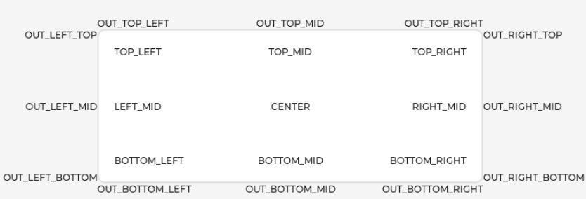
- Alignment Positioning of LVGL Controls
- Function: Enables the control to be positioned offset based on a reference point. The center of the reference point control to which the control is aligned for the offset.
- Alignment standard: The LVGL library has both internal and external alignment. By default, the top-left corner is used as the origin, left is the positive horizontal direction, and down is the positive vertical direction.
lv_obj_align(btn, LV_ALIGN_CENTER, -50 , 50);//Position the btn control 50 pixels left of center and 50 pixels down
- Styling of LVGL controls
- Function: Enables the control to be rendered according to a set style. Using the lv_obj_add_style function you can realize the rendering of each part of the control in different states.
static lv_style_t style_base;
lv_style_init(&style_base);                                                          //Initialize the style
lv_style_set_bg_color(&style_base, lv_palette_main(LV_PALETTE_LIGHT_GREEN));         //Set the background color
lv_style_set_border_color(&style_base, lv_palette_darken(LV_PALETTE_LIGHT_GREEN, 3));//Set the border color
lv_style_set_border_width(&style_base, 2);                                           //Set the edit width
lv_style_set_radius(&style_base, 10);                                                //Setting the size of the corner radius
lv_style_set_shadow_width(&style_base, 10);                                          //Set the width of the shadow

lv_obj_add_style(btn,&style_base,0);                                                 //Set the style of the btn theme, 0 can be replaced by the position and state
- LVGL control group add function
- Function: Incorporates the LVGL control into a control group so that the encoder input device can enter edit mode to modify the state of the control.
lv_group_add_obj(group, btn);//Add the btn control to the group of controls