


- sales/support
Google Chat: zj734465502@gmail.com
- sales
+86-0755-88291180
- sales01
sales01@spotpear.com
- sales02
dragon_manager@163.com
- support
services01@spotpear.com
- CEO-Complaints
manager01@spotpear.com
- sales/support
WhatsApp:13246739196
Raspberry Pi 70H-1024600-IPS/QLED User Guide
Overview
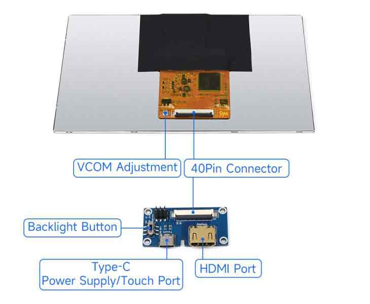
The 70H-1024600 series display, designed by Waveshare Team, is for customers who need a lightweight HDMI display. As it is thinner and lighter than any traditional HDMI display, users can do the second development by themselves easily.
For simplifying the display, we integrate the power supply, display, touch, and control signal as the 40PIN multi-functional header. Just need an FPC cable, you can lower the project cost with the thinnest display, and apply it in any embedded projects.
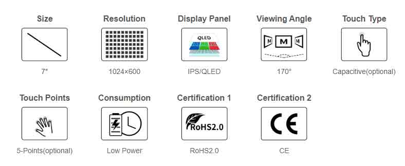
Feature
- 7-inch IPS/QLED screen, 1024 x 600 hardware resolution.
- Capacitive touch, support five-point touch (this function is only for the touch version).
- COF thin and light structure, providing 40PIN interface one-line communication, integrated development is more convenient.
- High compatibility, when used with development accessories, it supports main control boards such as Raspberry Pi, PC, and Jetson nano.
- Support backlight control, more power saving.
Specification
| Item | Description | Unit |
|---|---|---|
| Product Model | 70H-1024600 Series | |
| Size | 7.0 | Inch |
| Viewing Angle | 170 | Deg |
| Resolution | 1024 (RGB) × 600 | Pixels |
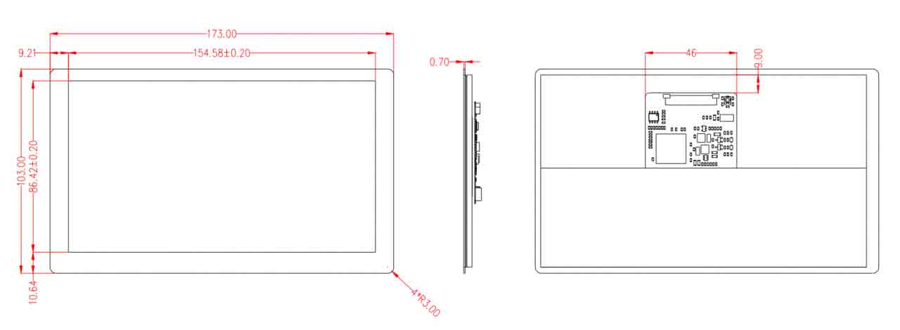
| Touch Screen Size | 173 (H) × 103 (V) × 4.2 (D) | mm |
| Display Size | 164 (H) × 97 (V) × 3.5 (D) | mm |
| Display Area | 154.2144 (W) × 85.92 (H) | mm |
| Pixel Pitch | 0.1506 (H) x 0.1432 (V) | mm |
| IPS Version Color Gamut | 45%NTSC | |
| QLED Version Color Gamut | 78%NTSC | |
| Brightness | 350 | cd/m² |
| Backlight Adjustment Method | PWM software dimming | |
| Contrast | 800:1 | |
| Color Depth | 16.7M | |
| Refresh Rate | 60 | Hz |
| User Interface | 40PIN 0.5mm FPC | |
| Weight | Note1 | g |
| Power Consumption | Note2 | Watt |
- Note 1: 70H-1024600-IPS=94g, 70H-1024600-IPS-CT=153g, 70H-1024600-QLED=106g, 70H-1024600-QLED-CT=165g.
- Note 2: 70H-1024600-IPS=2.15W, 70H-1024600-IPS-CT=2.3W, 70H-1024600-QLED=2.15W, 70H-1024600-QLED-CT = 2.3W.
Electrical Specifications
| Parameter | Minimum value | Standard value | Max value | Unit | Note |
| Input Voltage | 4.75 | 5.00 | 5.25 | V | Note 1 |
| Input Current | 500 | 500 | TBD | mA | Note 2 |
| Output Voltage | 3.1 | 3.3 | 3.5 | V | Note 1 |
| Output Current | 0 | 200 | 200 | mA | Note 3 |
| Operating temperature | -10 | 25 | 70 | ℃ | Note 4 |
| Storage temperature | -20 | 25 | 80 | ℃ | Note 4 |
| Operating Humidity | 10 | 60 | 90 | %RH | Note 4 |
- Note 1: Input voltage/output voltage exceeding the maximum value or improper operation may cause permanent damage to the device.
- Note 2: Input current/output current must be greater than 500mA, otherwise it will cause startup failure or abnormal display, and it may cause permanent damage to the device if it is in an abnormal state for a long time.
- Note 3: The output current needs to be less than 200mA, otherwise it will fail to be started or display abnormally, and it may cause permanent damage to the device if it is in an abnormal state for a long time.
- Note 4: Please do not store the display in a high-temperature and high-humidity environment for a long time. The display must work within the limited value range, otherwise, the display may be damaged.
Interface Definition
| PIN | Logo | Function Description |
|---|---|---|
| 1~3 | NC | Not Connect |
| 4~6 | 5V IN | DC 5V power input |
| 7 | 3V3 OUT | DC 3.3V power output |
| 8~10 | GND | Ground (0V) |
| 11 | TMDS Data2+ | Differential data signal |
| 12 | GND | Ground (0V) |
| 13 | TMDS Data2- | Differential data signal |
| 14 | TMDS Data1+ | Differential data signal |
| 15 | GND | Ground (0V) |
| 16 | TMDS Data1- | Differential data signal |
| 17 | TMDS Data0+ | Differential data signal |
| 18 | GND | Ground (0V) |
| 19 | TMDS Data0- | Differential data signal |
| 20 | TMDS Clock+ | Differential data signal |
| 21 | GND | Ground (0V) |
| 22 | TMDS Clock- | Differential data signal |
| 23 | CEC | Consumer Electronics Control Signals |
| 24 | SCL | I2C clock line, internal 10kΩ pull-up |
| 25 | SDA | I2C data line, internal 10kΩ pull-up |
| 26 | GND | Ground (0V) |
| 27 | +5V Power | With HPD to achieve insertion detection |
| 28 | Hot Plug Detect | Hot Plug Detect Signal |
| 29~32 | NC | Not Connect |
| 33 | D+ | USB differential data signal |
| 34 | D- | USB differential data signal |
| 35 | GND | Ground (0V) |
| 36 | BL_PWM | Display backlight adjustment |
| 37 | BL_EN | Display backlight enable |
| 38~40 | NC | Not Connect |
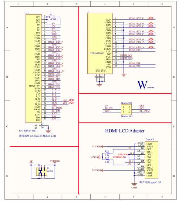
Adapter Board Design
You can refer to adapter board schematic to integrate the display, please note:
- HDMI needs to use an equal-length differential cable, and the differential impedance of the four pairs of differential signals needs to be controlled at 100Ω±10%.
- The four-pair differential signal cables of HDMI are required to be less than 5 inches.
- The length deviation within the HDMI differential pair is required to be controlled within 20mil, and the maximum shall not exceed 25mil.
- The interface ESD device needs to be placed close to the HDMI socket.
- The 5V power input line needs a wide enough path, it is recommended to exceed 30mil to ensure that the voltage input will not have an excessive loss.
- Pay attention to the line and direction to prevent reverse connection.
Structure Design
NOTE: The assembly materials used below are not included in the shipped kit! ! This is only for reference.
3D Print Shell Solution
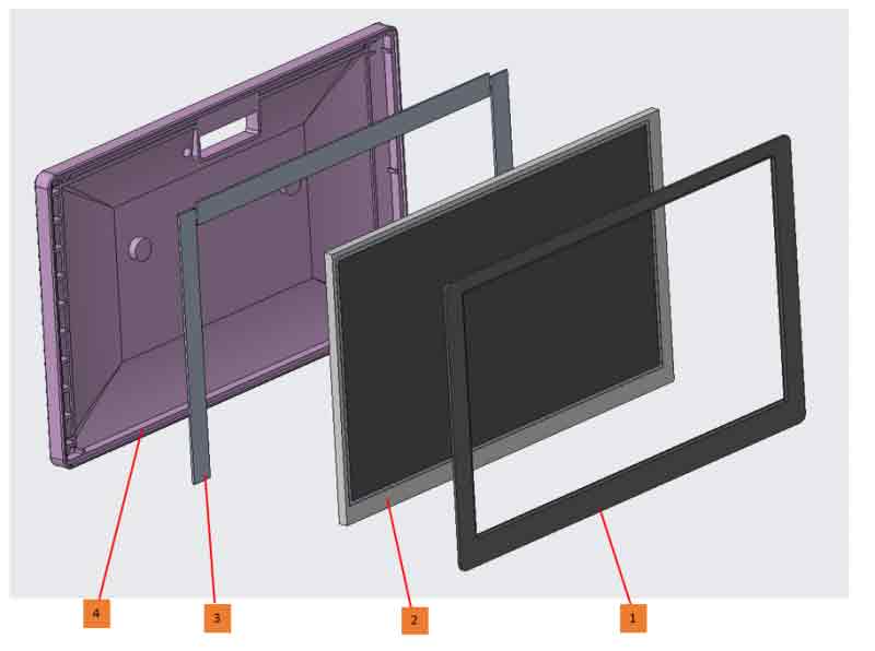
Name:
1. The front panel comes with adhesive backing
2. 70H-1024600-IPS/QLED
3. Adhesive foam
4. Rear case
Assembly Instructions:
Affix the back of the display screen (part 2) with a suitable thickness of adhesive foam (part 3), then directly embed the display screen (part 2) into the rear case (part 4), and then paste the front panel (part 1) to the corresponding location.
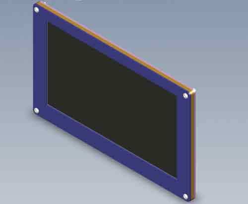
How to Fix the Acrylic
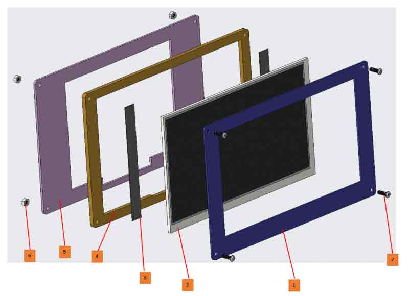
Name:
1. Front panel (1.5mm thick acrylic board is recommended)
2. 70H-1024600-IPS/QLED
3. Adhesive foam
4. Medium plate (It is recommended to use an acrylic plate with a thickness of more than 3.5mm)
5. Bottom plate (It is recommended to use an acrylic plate with a thickness of more than 2mm)
6. Nuts
7. Pan head screws
Assembly Instructions:
Align the front panel (part 1) and the midplane (part 4) and thread the screws (part 7) into the display (part 2) Paste a suitable thickness of adhesive foam (part 3) on the back of the display screen, then install the bottom plate (part 5), and finally lock the nut (part 6).
Note: The LCD display surface cannot be installed parallel to the ground, otherwise it will fall off under the action of gravity. In addition, when it needs to be installed at an angle, the back of the LCD screen should keep at least an angle of less than 75 degrees with the horizontal direction.
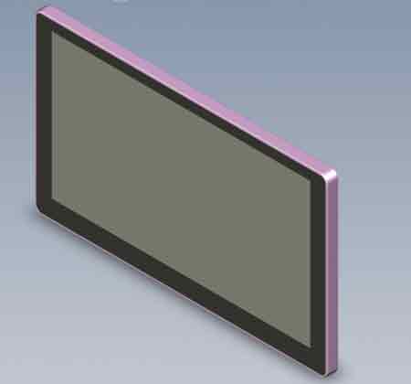
Assembly 3D Drawing
- 3D printing shell:
- Acrylic fixed effect:
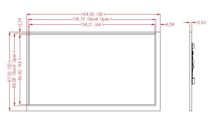
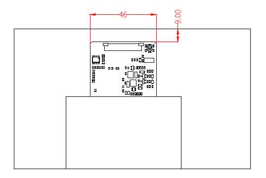
CAD Drawing
to be continued...
EDID Timing Parameters
If the system of the main control board can automatically identify the EDID for display, there is no need to set additional timing parameters.
Otherwise, you can refer to the following EDID settings:
| Pixel Clock | H Adressable | H Blanking | V Adressable | V Blanking | H Front Porch | H Sync Width | V Front Porch | V Sync Width | H Image Size | V Image Size | H Border | V Border |
|---|---|---|---|---|---|---|---|---|---|---|---|---|
| 49.00 | 1024 | 288 | 600 | 24 | 48 | 96 | 3 | 10 | 154 | 86 | 0 | 0 |
How to Develop
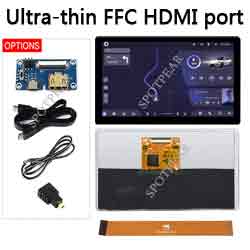
- If you are using the Waveshare 70H-1024600 series touch display screen for the first time, it is recommended to use it with the development accessories:
| Adapter board pin header definition | Function introduction |
|---|---|
| 5V | DC 5V power input |
| 3V3 | DC 3.3V power output |
| GND | Ground (0V) |
| EN | Backlight enable |
| PWM | Backlight adjustment |
| IO | NC |
Working with PC
- Support Windows 11/10/8.1/8/7 system. Instructions:
- Use the FPC-Cable-15cm to connect the 70H-1024600 display screen to the development accessories (pay attention to the cable direction, 1 to 1, 40 to 40 serial number connection).
- Connect the Display interface to the PC HDMI interface.
- Connect the Touch interface to the USB interface of the PC.
- Hardware Connection:
- Notice:
- Some PCs do not support plug-and-play with HDMI devices. Generally, they can be used normally after restarting the system.
- Insufficient power supply of the USB interface of some PCs will cause the LCD screen to flicker, which can be restored to normal use after connecting to an external 5V/1A power supply.
PWM Light Adjustment
Connect the GND of the microcontroller (such as a potentiometer) to the GND pin in the figure below, and connect the voltage output terminal (DC 0~3.3V) of the microcontroller to the PWM pin as shown in the figure below so as to control the backlight brightness by changing the voltage.
Note: DC 3.3V is the darkest and 0V is the brightest.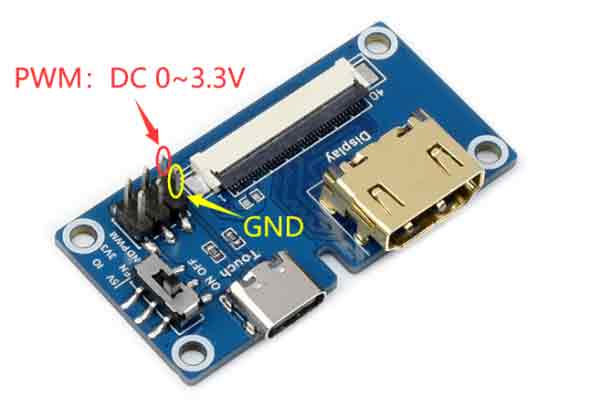
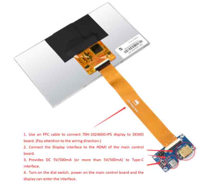
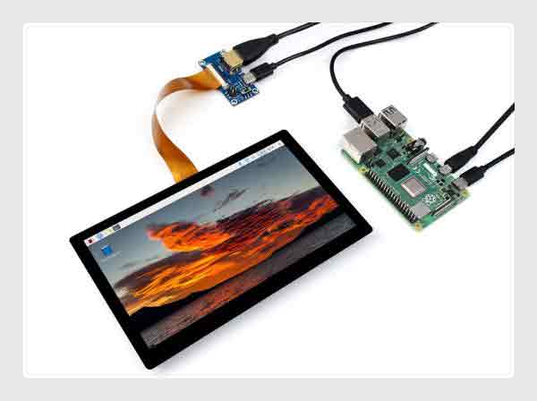
Working with Raspberry Pi
Hardware Connection
- Use the FPC-Cable-15cm to connect the 70H-1024600 touch screen to the Demo board (pay attention to the cable direction, 1 to 1, 40 to 40 serial number connection).
- Connect the Display port to the Raspberry Pi HDMI port.
- Connect the Touch port to the USB port of the Raspberry Pi.
Software Setting
- Support Raspberry Pi OS / Ubuntu / Kali and Retropie systems.When the LCD works on systems such as Raspberry Pi, the resolution must be set manually, otherwise, the display resolution will be incorrect and the experience will be affected.
1. Please download the latest version of the image from Raspberry Pi official website.
2. Download the compressed file to the PC and extract it to get the .img file.
3. Connect the TF card to the PC, use the SDFormatter software to format the TF card.
4. Open the Win32DiskImager software, select the system image prepared in step 1, and click write to burn the system image.
5. After the programming is completed, open the config.txt file in the root directory of the TF card, add the following code at the end of config.txt, save and safely eject the TF card.
hdmi_group=2
hdmi_mode=87
hdmi_cvt 1024 600 60 6 0 0 0
hdmi_drive=1
6. Insert the TF card into the Raspberry Pi, power on the Raspberry Pi, and wait for a few seconds to display normally.
PWM Software Light Adjustment
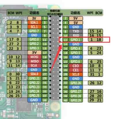
- Raspberry Pi bullseye system with development accessories as an example.
- Hardware connection: Connect the PWM pin of the development accessory to the P1 pin of the Raspberry Pi (as shown in the figure below) and the GND pin to any GND of the Raspberry Pi.
- On Software:
Upgrade the Wiring Pi:
wget https://project-downloads.drogon.net/wiringpi-latest.deb
sudo dpkg -i wiringpi-latest.deb
gpio -v
# Run gpio -v and version 2.52 will appear. If it does not appear, the installation is wrong.
After the wiringPi is updated successfully, the backlight brightness can be controlled by the following commands.
gpio -g mode 18 pwm #Occupied pins are PWM pins
gpio pwmc 100
gpio -g pwm 18 0 #brightest
gpio -g pwm 18 1023 #darkest
gpio -g mode 18 out #Release as output