


- sales/support
Google Chat: zj734465502@gmail.com
- sales
+86-0755-88291180
- sales01
sales01@spotpear.com
- sales02
dragon_manager@163.com
- support
services01@spotpear.com
- CEO-Complaints
manager01@spotpear.com
- sales/support
WhatsApp:13246739196
Raspberry Pi Compute Module 4 User Guide
Product description
I am the 4th generation IO board of the Raspberry Pi Compute Module. The Compute Module 4 IO Board is a baseboard officially released by the Raspberry Pi that can be used with the Raspberry Pi Compute Module 4. It can be used as the development system of the Compute Module 4 and as a Embedded boards are integrated into end products, or systems can be created quickly using off-the-shelf components such as Raspberry Pi expansion boards and PCIe modules. Its interface is concentrated on the same side, which is convenient for users to use.
Product dimension
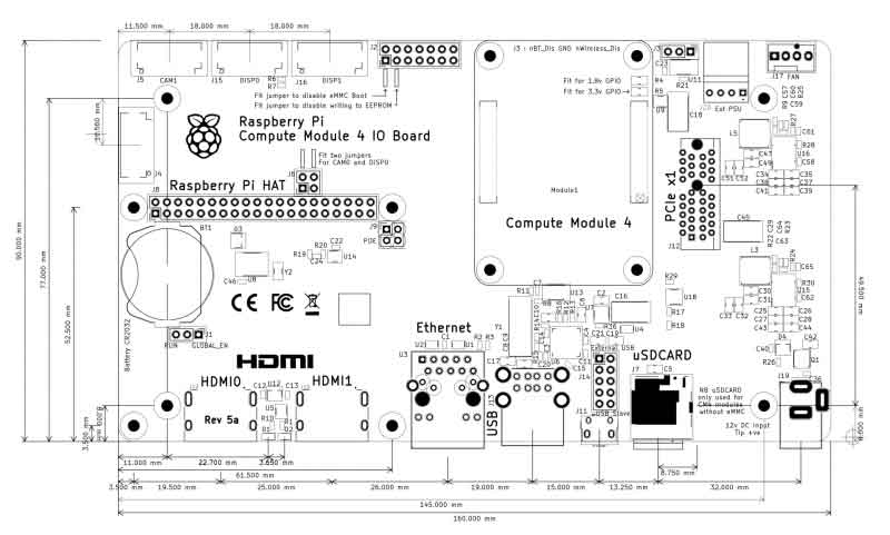
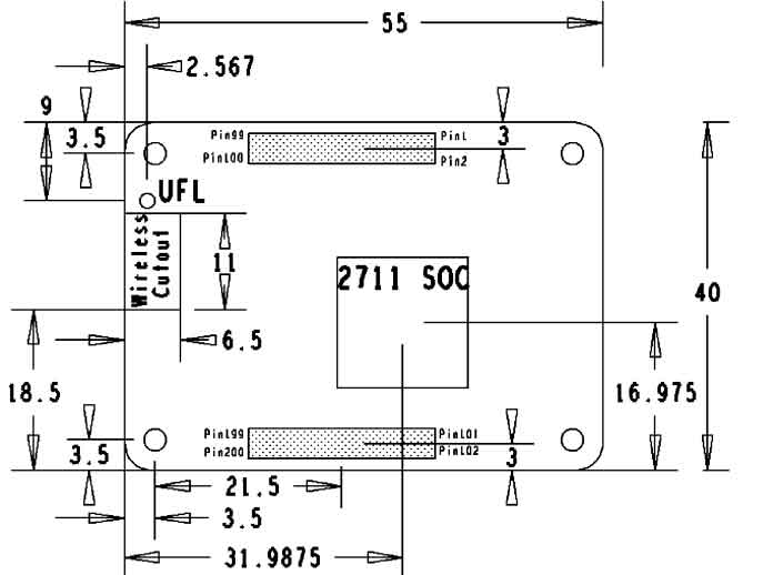
For more description, please visit: module 4_IO board
Notes
Do not plug or unplug any device while it is powered on
Writing Image
- Write Image for Compute Module Boards eMMC version
- Write Image for Compute Module Boards Lite version
USB2.0
The USB port is disabled by default on the CM4 to save power. If you need to start, you need to add the following to the config.txt file:
dtoverlay=dwc2,dr_mode=host
After restarting
If you use the latest Raspberry Pi OS (image after October 30, 2021) USB2.0 is OTG mode by default, CM4 will report an error:
config failed, hub doesn't have any ports! (err -19)
However, USB can still be used. If you want to remove this error, remove otg_mode=1 in [cm4] of config.txt, and add dtoverlay=dwc2, dr_mode=host (USB cannot be recognized without adding it).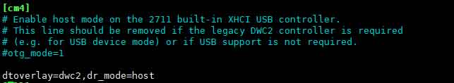
PCIe Gen 2 x1
PCle sockets are designed to accept standard PC PCle cards. You should make sure you have an OS driver for your card.
The PCle link has been successfully used with NVMe drives via a passive PCle adapter.
Note: PCle interface does not support MSI-X. Typical PCle devices will fall back to MSI.
RTC FAN
This extended version only supports 12V fan voltage
- Note: Please connect the fan before turning on the power of the base board and then complete the test. Please do not connect the fan after the base board is powered on, because the fan control chip has been powered on, otherwise the chip will be burned!
- Note: Before connecting, please confirm whether the rated voltage of the fan is consistent with the voltage actually connected to the fan.
Please note that DSI and CSI are prohibited when using RTC.
I2C-10 is used by default
RTC (PCF85063a) on i2c-10, address is 0x51 (7-bit address)
FAN ( EMC2301 ) on i2c-10, address is 0x2f (7-bit address)
RTC
sudo nano /boot/config.txt
 #Add the following lines at the end
 dtparam=i2c_vc=on
 dtoverlay=i2c-rtc,pcf85063a,i2c_csi_dsi
 #Add # in front of dtparam=audio=on
 #dtparam=audio=on
 #Save and exit, restart
 sudo reboot
How to use Hwclock
Synchronize system clock to hardware clock
sudo hwclock -w
Synchronize hardware clock to system clock
sudo hwclock -s
 #The network or the NTP needs to be closed, otherwise it will be changed back.
Set the hardware clock time:
sudo hwclock --set --date="9/8/2021 16:45:05"View hardware clock
sudo hwclock -r
Display version information
sudo hwclock --verbose
Fan
When powered on, the fan will spin for 1 second, then stop for 2 seconds, and then spin again, this is a normal phenomenon
There is no official configuration method for the fan currently , there is a third-party configuration method: https://github.com/neg2led/cm4io-fan
This method is published by a third party, and we are not responsible for any problems!
mkdir -p ~/src
 cd ~/src
 git clone https://github.com/neg2led/cm4io-fan.git
 cd cm4io-fan
 sudo chmod 777 install.sh
 sudo ./install.sh
 #The following is a description of config.txt
 #############################
 Name: cm4io-fan
 Info: Raspberry Pi Compute Module 4 IO Board fan controller
 Load: dtoverlay=cm4io-fan,<param>[=<val>]
 Params: minrpm RPM target for the fan when the SoC is below
                            mintemp (default 3500)
        maxrpm RPM target for the fan when the SoC is above
                            maxtemp (default 5500)
        midtemp Temperature (in millicelcius) at which the fan
                            begins to speed up (default 50000)
        midtemp_hyst Temperature delta (in millicelcius) below mintemp
                            at which the fan will drop to minrpm (default 2000)
        maxtemp Temperature (in millicelcius) at which the fan
                            will be held at maxrpm (default 70000)
        maxtemp_hyst Temperature delta (in millicelcius) below maxtemp
                            at which the fan begins to slow down (default 2000)
  #############################
Or directly refer to the following:
dtoverlay=cm4io-fan,minrpm=500,maxrpm=5000,midtemp=45000,midtemp_hyst=2000,maxtemp=50000,maxtemp_hyst=2000
The fan will start to accelerate when temperature is higher than 45 degrees Celsius, and will up to the highest speed when higher than 50 degrees Celsius.
CSI DSI
Configuration file
CSI and DSI are disabled by default. When using the camera and DSI, it will occupy three I2C devices: I2C-10, I2C-11, and I2C-0.
- Open a terminal and run the following commands:
wget https://www.waveshare.net/w/upload/7/75/CM4_dt_blob_Source.zip
 unzip -o  CM4_dt_blob_Source.zip -d ./CM4_dt_blob_Source
 sudo chmod 777 -R CM4_dt_blob_Source
 cd CM4_dt_blob_Source/
 #If you want to use both cameras and DSI0
 sudo  dtc -I dts -O dtb -o /boot/dt-blob.bin dt-blob-disp0-double_cam.dts
 #If you want to ue both cameras and DSI1
 sudo  dtc -I dts -O dtb -o /boot/dt-blob.bin dt-blob-disp1-double_cam.dts
 #When using any DSI interface, HDMI1 will have no image output, even if you do not connect the DSI screen, as long as you compile the corresponding file, then HDMI1 will not output
  #If you need to restore, please delete the corresponding dt-blob.bin: sudo rm -rf /boot/dt-blob.bin
  # After execution, turn off the power and restart the CM4
Recording test
And then connect the cameras and DSI display
1: Please power off the IO Board first before your connection.
2: Connect the power adapter after connecting the cameras and DSI display
3: Wait a few seconds before the screen boot up.
4: If the DSI LCD cannot display, please check if you have added /boot/dt-blob.bin. If there already has the dt-blob.bin, just try to reboot.
5: The camera needs to be enabled by raspi-config, enter sudo raspi-config on the terminal, choose Interfacing Options->Camera->Yes->Finish-Yes and reboot the system
Old Version (Buster)
- Test the Cameras:
Test camera0:
sudo raspivid -t 0 -cs 0
Test camera1:
sudo raspivid -t 0 -cs 1
New Version (Bullseye)
If you are using the latest Raspberry Pi OS (Bullseye):
libcamera-hello -t 0
or
libcamera-hello

#The new system uses dual cameras
#Remove or comment out the line camera_auto_detect=1 in config.txt
#camera_auto_detect=1

#Add the following lines:
dtoverlay=imx219,cam1
dtoverlay=imx219,cam0

#Add the corresponding line according to the camera you use, where imx219 is the camera sensor model, and there are other sensors
dtoverlay=ov5647,cam0
dtoverlay=imx219,cam0
dtoverlay=ov9281,cam0
dtoverlay=imx477,cam0

#then restart
reboot

#Other part of the commands:
#Check if the camera is detected
libcamera-hello --list-cameras

#Open the corresponding camera
libcamera-hello --camera 1
libcamera-hello --camera 0

#Taking Pictures
libcamera-jpeg -o test.jpg
#You can add --camera to specify the camera
More instructions click me
- HDMI1 is disabled if you use DSI interfaces for displaying, even if you just compile the corresponding files without connecting to the DSI screen, please note it
- Any connection of two HDMI ports can output images, not limited to which HDMI port, if two HDMI screens are connected, only HDMI0 has image output
- If you want to enable both HDMI, please delete the dt-blob.bin file with the following command:
sudo rm -rf /boot/dt-blob.bin
- Then reboot
Reference Raspberry Pi Manual