- sales/support
Google Chat: zj734465502@gmail.com
- sales
+86-0755-88291180
- sales01
sales01@spotpear.com
- sales02
dragon_manager@163.com
- support
services01@spotpear.com
- CEO-Complaints
manager01@spotpear.com
- sales/support
WhatsApp:13246739196
- HOME
- >
- ARTICLES
- >
- For Arduino
- >
- Mother Board
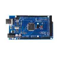
Arduino MEGA2560 R3 User Guide
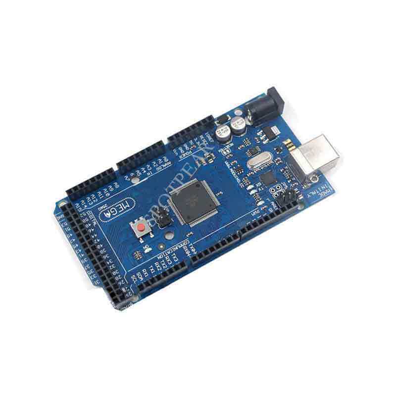
Arduino Mega 2560
There are cheaper Arduino boards on the market. Why choose Arduino Mega? The main reason is that this board is more convenient for expansion. Arduino Mega 2560 has many features that other boards do not have. For example: it has built-in 16 analog sensors and 54 digital sensor interfaces, and supports USART and other communication modes. Built-in RTC and other functions, such as analog comparator, advanced timer, controller wake-up mechanism interrupt, etc., 16MHz crystal clock can get 16 MIBS, and it saves power and is fast. There are more than 5 sets of Vcc and Gnd pins, which can easily connect other devices to the Arduino Mega 2560.
Other features of the Arduino Mega 2560 include JTAG support for programming, debugging and troubleshooting; large flash and SRAM that can easily handle bulky programs; it is also compatible with different types of modules such as high-level (5V) or low-voltage Flat (3.3V) and I/O ref pins; it supports ICSP and USB microcontroller programming on the PC side. The Arduino Mega 2560 is a replacement for the older model Arduino Mega, so, it will be named the "2560" extension. So for some more complex projects, this is an excellent choice.
Arduino Mega 2560 Hardware Specifications
| Arduino Mega 2560 | Hardware Specifications |
|---|---|
| Microcontroller | AVR ATmega 2560 (8bit) |
| Power | 7-12V (Built-in regulator control) |
| Digital I/O Pins | 54 |
| Analog I/O Pins | 16 |
| Total Digital I/O | 70 (Digital + Analog) |
| Clock frequency | 16 MHz (F default setting 1Mhz) |
| Flash Memory | 128 KB |
| SRAM | 8 KB |
| Communication method | USB (Programming with ATmega 8), ICSP (programming), SPI, I2C and USART |
Arduino Mega Feature
| Arduino Mega | Feature |
|---|---|
| Timer | 2 (8bit) + 4 (16bit) = 6 timer |
| PWM | 12 (2-16 bit) |
| ADC | 16 (10 bit) |
| USART | 4 |
| Pin Change Interrupt | 24 |
The Arduino Mega 2560 also adds features such as analog comparators, external and software interrupts, power save mode, built-in temperature sensor, RTC, and more.
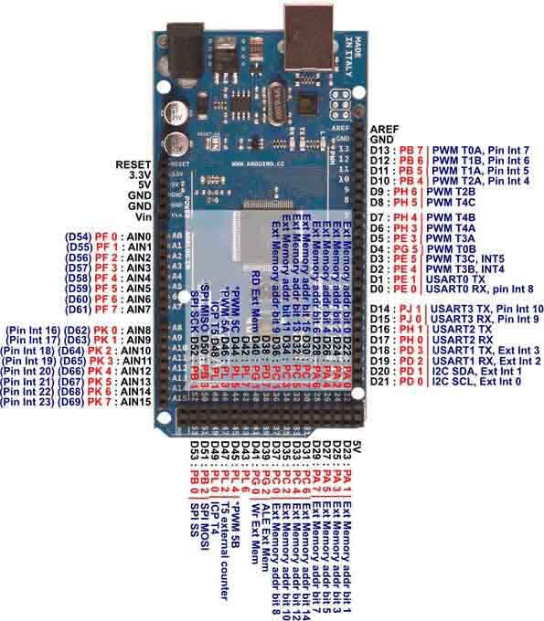
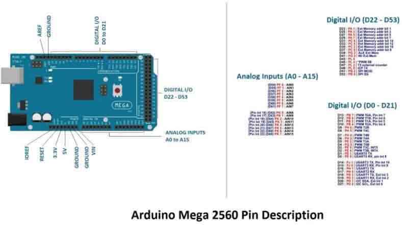
Arduino Mega Interface definition
Power pin:
| Arduino Mega | Power Pin |
|---|---|
| VIN | Supply voltage (7-12V) |
| GND | land |
| 5V Power | For external module power supply |
| 3.3V Power | For external module power supply |
Arduino Mega interface partition
Control pin:
RESET: (Reset input) The low level of this pin exceeds 4 clock cycles and the board will reset. The Arduino Mega has a built-in reset circuit, a key reset system, and can be used as a reset controller for other devices.
XTAL1,XTAL2: The crystal oscillator (16Mhz) is connected to the controller clock and is grounded through 2 bypass capacitors.
AREF: Using this pin, when we use ADC for analog-to-digital conversion, use external reference voltage for conversion instead of reference voltage from internal 1.1V or 5v reference.
Digital PIN(70):
Digital pin: 0-53 (Digital pin) and 0-15 (Analog pin) can be used as input or output of digital sensor or module, use pinMode() to determine the function of the pin, digitalWrite() indicates pin write, digitalRead ( ) indicates the read status of the needle.
Example
Example: output low level signal on Arduino mega:
Example: input read signal on Arduino mega:
Analog PIN(16):
Analog Pin:0-15 (Analog pin) can be used as analog input pin of ADC, if not used, it can be used as normal digital pin. Use pinMode() to determine the function of the pin, and analogRead() can read the pin state and get the digital value of the analog signal, but you must pay attention to the selection of the internal or external reference voltage and the Aref pin voltage.
Example
Example: input analog signal on Arduino mega:
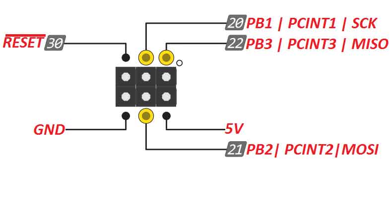
SPI Pins:
These pins are used for serial communication with the SPI protocol, typically for communication between 2 or more devices. The SPI enable bit must be set to communicate with other devices.
I2C Pins:
The Digital pin 20 is the SDA of the I2C pin, and the Digital pin 21 is the SCK (400Khz) of the I2C pin. Use the function wire.begin() to start I2C, wire.read() to read I2C data, and wire.write() to write I2C data.
Example
I2c master-slave data read:
PWM PIN:
Digital pins 2-13 can be used as PWM output, use analowrite() to write the PWM value, range: 0-255. It uses a filter to obtain an analog signal at the output, which is an alternative to low-cost DAC systems.
Example
Arduino mega Output continuous analog signal:
USART PIN:
USART pin: used for serial communication with pc or other devices for data sharing and logging. It is used with serialBegin() to set the serial port baud rate, and to start communicating with serial.Println() to output and print strings on the serial device.
Example
For example: set the serial port baud rate to 9600, and print "hello" on the serial port:
Pinchange Interrupt Pin:
These pins are used for pin replacement interrupts. The enable pinchange interrupt bit must be set to global interrupt enable.
Example
For rotary encoders, push-button interrupts, etc.
Hardware interrupt pin:
Digital pins 18 – 21, 2, 3 are hardware interrupt pins for hardware interrupt service. Hardware interrupts must have global interrupts enabled in order to get interrupts from other devices.
Example
Used for ISR program button, external device wake-up controller, ultrasonic and other sensors.
Arduino Megaother components
DC power interface:
This interface can be used to provide an external power supply in the 7-12V range to the Arduino Mega. The Arduino Mega R3 has 5v and 3.3v voltage regulators to regulate power to the Arduino controllers and sensors.
ICSP 1 (ATmega8) and 2 (AVR 2560):
ICSP is an interface for online programming of programs using the SPI protocol through the serial port.
Reset key:
Reset key: Built-in capacitor reset circuit, button reset circuit and resistance reset circuit. The reset button can be used to get a 4-cycle low signal on the reset pin to put the controller in reset mode.