


- sales/support
Google Chat: zj734465502@gmail.com
- sales
+86-0755-88291180
- sales01
sales01@spotpear.com
- sales02
dragon_manager@163.com
- support
services01@spotpear.com
- CEO-Complaints
manager01@spotpear.com
- sales/support
WhatsApp:13246739196
Raspberry Pi Compute Module IO Board Plus User Guide
Introduction
Compute Module Board Plus, Compisite Breakout Board fir Developing with Raspberry Pi CM3, CM3L
User Guide
Download demo codes
- Please download demo codes from [#Resource].
- After you write image to SD card or EMMC, you can copy the demo codes downloaded to BOOT directly.(If you use the pre-configured image, this step isn't required).
- Downlaod rpiboot_setup software from [#Resource] and unzip it. Install rpiboot software and remember the installation directory.
Writting image
On Compute Module IO Board Plus (Hereafter called as IO Board), a SD card slot is integraed for image installation of Compute Module 3 Lite (hereafer calles as CM3L) and Compute Module 3+ Lite(hereafter called as CM3+L). If the board you use is Compute Module 3 (CM3) or Compute Module 3+ (CM3+), image is writted to EMMC and booting instead of SD card.
Download image
- Download the newest Raspbain image from Raspberry Pi website or download the pre-configured images from [#Resource].
- Unzip the file downloaded to get .img file.
Write image for CM3L/CM3+L
- To write image, you should prepare an SD card (16G or larget) and card reader.
- Use Win32DiskImage.exe software to write image to SD card. (It is same as how you write image for Pi 3B)
- After writing, insert the SD card to the card slot of IO Board.
Write image for CM3/CM3+
- Download Raspbian image and unzip it to get .img file.
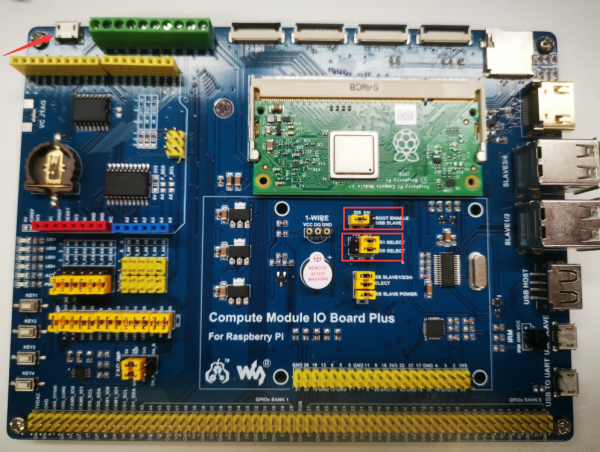
- Insert CM3/CM3+ to IO Board, set BOOT ENABLE USB SLAVE jumper to EN side, remove USB SLAVE1/2/3/4 Select jumper caps. Connect USB SLAVE of IO Board to PC.
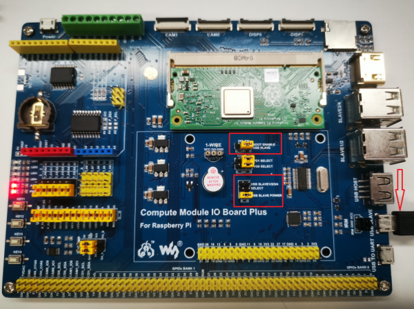
- Go to installation directory of rpiboot_setup, find rpiboot.exe and run it as administrator. After executing rpiboot, CM3/CM3+ will be recognized as a storage drive.(If the CM3+ is the first time to be used, you may need to format it and allocate a letter for it. )
- Use WinDiskImager.exe tool to write image downloaded to EMMC of CM3/CM3+. (Please first format it)
- After writing, please set BOOT ENABLE USB SLAVE jumper back to DIS side and insert USB SLAVE1/2/3/4 Select jumpers back.
- Connect Power adapter to Power interface to start devices.
【Note】
- While writing image, DO NOT write other portable storage drive to avoid conflicting. The EMMC of CM3+ is extended, which allows CM3+ to install common desktop image. Because EMMC of CM3 is only 4G, therefore if you want to write image to CM3, please choose Raspbian Lite. You can also install GUI for Lite image separately by commands below (network is required)
sudo apt-get update
sudo apt-get install raspberrypi-ui-mods
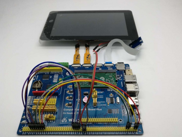
Connect display and camera
If you use the pre-configured image, you only need to connect the devices and use them. If the image you use is official Raspbain, you also need to configure software for official display and camera.
Connect official Raspberry Pi 7inch display
- Connect official 7inch display to DISP1 interface of IO Board by adapter board.
- Wire 5V and GND pins of display to 5V and GND of IO Board.
- Wire pins:
- GPIO0 <-> CD1_SDA
- GPIO1 <-> CD1_SCL
- Connect power adapter
- Display is turn on after booting.
【Note】
- If the display work abnormally, please check hardware connection and software setting (software setting please refer to #Setup software for display and camera)
- We have several HDMI displays can be used for Raspberry Pi, here we take 7inch HDMI LCD (C) as example.
- Disconnect official DPI display, otherwise HDMI display cannot work.
- Connect HDMI interface of 7inch HDMI LCD (C) to HDMI interface of IO Board. Connect the Touch interface of display to USB port of IO Board.
- Connect power adapter
- Display is turned on after booting.
【Note】
- If you use Waveshare HDMI display, you need to config Raspbain according to WIKI page of display.
Connect Camera
- Connect camera to CAM1 interface of IOBoard.(You may require RPi zero V1.3 Camera cable)
- Wire:
- GPIO0 <-> CD1_SDA
- GPIO1 <-> CD1_SCL
- GPIO4 <-> CAM1_IO1
- GPIO5 <-> CAM1_IO0
- Connect power adapter
- You can connect two cameras at the same time by connecting another camera to CAM0 interface.
- Wire:
- GPIO28 <-> CD0_SDA
- GPIO29 <-> CD0_SCL
- GPIO30 <-> CAM0_IO1
- GPIO31 <-> CAM0_IO0
- To capture camera, please run commands:
- sudo raspivid -t 0 -cs 0
- sudo raspivid -t 0 -cs 1
【Note】
- -cs is used to choose camera 0 or 1; 0 for CAM1 and 1 for CAM0
- The parameter of -cs stand for the number of the camera connected, it may be different with the silk screen printing on the board. If you only connect one camera and connect it to the CAM1 interface, the command should be run is also "-cs 0", it means that it will call the first camera (camera 0).
Setup software for display and camera
If you use official Raspbian, you need to setup software for using official display and the cameras as well. Convert dts file to bin and then put it to /boot directory. (dts files are provided in demo codes, located in /Program/dt)
Covnert commands:
sudo dtc -I dts -O dtb -o /boot/dt-blob.bin dt-blob-disp1-cam2.dts
If you use pre-configured, you needn't to setup again.
Demo codes
To run the sample codes, you should connect display and keyboard to Raspberry Pi for controlling, or you can remotely access Raspberry Pi via SSH.
If you use original Raspbian image, please first install libraries before runing example. Details of libraries installation, please refer to Libraries for Pi
PWM: Buzzer testing
- Python
- Open terminal and enter directory of codes by command:
cd /home/pi/CM3/Buzzer_PWM/python/
- Run example by command:
sudo ./buzzer.py
- wiringPi
- Open terminal and enter directory of codes by command:
cd /home/pi/CM3/Buzzer_PWM/wiringPi/
- Run example by command:
sudo ./buzzer
- Expected result
:The sound of buzzer first turns higher and then turns lower back. 【Note】When using the IO Board, buzzer may sound because of GPIO conflict, in this case, you can directly remove the last BUZ jumper cap of USER_JMP.
DAC testing
- BCM2835
- Open terminal and enter directory of codes by command:
cd /home/pi/CM3/DAC8532
- Run example by command:
sudo ./dac8532
- Expected result
- LED1 and LED2 flash repectively, turns brighter from dim and then turn to dim again.
DS18B20 testing
You should prepare a DS18B20 for this exmaple. Connect it to IO Board according to screen printing. DO NOT reverse it to avoid from high hot.
- sysfs
- Open terminal and enter directory of codes by command:
cd /home/pi/CM3/DS18B20/fs/
- Run example by command:
sudo ./ds18b20
- Python
- Open terminal and enter directory of codes by command:
cd /home/pi/CM3/DS18B20/python/
- Run example by command:
sudo ./ds18b20.py
- Expected result
- Current temperature measured is printed to terminal, you can press Ctr+C to stop process.
RTC: DS3231 testing
- BCM2835
- Open terminal and enter directory of codes by command:
cd /home/pi/CM3/DS3231/bcm2835/
- Run example by command:
sudo ./ds3231
- wirignPi
- Open terminal and enter directory of codes by command:
cd /home/pi/CM3/DS3231/wiringPi/
- Run example by command:
sudo ./ds3231
- Python
- Open terminal and enter directory of codes by command:
cd /home/pi/CM3/DS3231/python/
- Run example by command:
sudo ./ds3231.py
- Expected result
- Time information is printed to terminal, you can press Ctrl+C to stop process.
IRM Infrared remotely control testing
- Here we should use Infrared controller.
- BCM2835
- Open terminal and enter directory of codes by command:
cd /home/pi/CM3/IRM/bcm2835/
- Run example by command:
sudo ./irm
- wiringPi
- Open terminal and enter directory of codes by command:
cd /home/pi/CM3/IRM/wiringPi/
- Run example by command:
sudo ./irm.py
- Expected result
- Terminal prints relate key value when press controller. You can press Ctrl+C to stop process.
Button testing
- BCM2835
- Open terminal and enter directory of codes by command:
cd /home/pi/CM3/KEY/bcm2835/
- Run example by command:
sudo ./key
- wirignPi
- Open terminal and enter directory of codes by command:
cd /home/pi/CM3/KEY/wiringPi/
- Run example by command:
sudo ./key
- python
- Open terminal and enter directory of codes by command:
cd /home/pi/CM3/KEY/python/
- Run example by command:
sudo ./key.py
- Expected result
- Terminal print related information when you press KEY1, KEY2, KEY3 and KEY4 of IO Board. You can press Ctrl+C to stop process.
LED testing
- BCM2835
- Open terminal and enter directory of codes by command:
cd /home/pi/CM3/LED/bcm2835/
- Run example by command:
sudo ./led
- wiringPi
- Open terminal and enter directory of codes by command:
cd /home/pi/CM3/LED/wiringPi/
- Run example by command:
sudo ./led
- Python
- Open terminal and enter directory of codes by command:
cd /home/pi/CM3/LED/python/
- Run example by command:
sudo ./led.py
- Expected result
- 4 LED so IO Board flash respectively. You can press Ctrl + C to stop process.
ADC testing
- BCM2835
- Open terminal and enter directory of codes by command:
cd /home/pi/CM3/TLC1543/bcm2835/
- Run example by command:
sudo ./tlc1543
- wiringPi
- Open terminal and enter directory of codes by command:
cd /home/pi/CM3/TLC1543/wiringPi/
- Run example by command:
sudo ./tlc1543
- Python
- Open terminal and enter directory of codes by command:
cd /home/pi/CM3/TLC1543/python/
- Run example by command:
sudo ./tlc1543.py
- Expected result
- AD data are printed to terminal. You can press Ctrl+C to stop process.
UART communicatation testing
Connect USB TO UART interface of IO Board to PC. Open Putty software on PC and set it to 115200.
Access Raspberry by putty via UART port. (username and password are pi and raspberry)
- wirignPi
- Open terminal and enter directory of codes by command:
cd /home/pi/CM3/UART/wiringPi/
- Run example by command:
sudo ./uart
- Python
- Open terminal and enter directory of codes by command:
cd /home/pi/CM3/UART/python/
- Run example by command:
sudo ./usart.py
- Expected result
- String Hello World!!! are printed to Putty. You can press Ctrl+C to stop process.