- sales/support
Google Chat: zj734465502@gmail.com
- sales
+86-0755-88291180
- sales01
sales01@spotpear.com
- sales02
dragon_manager@163.com
- support
services01@spotpear.com
- CEO-Complaints
manager01@spotpear.com
- sales/support
WhatsApp:13246739196
- HOME
- >
- PRODUCTS
- >
- Other Board
- >
- STM32
- >
- Core
CoreH743I, STM32 STM32H743IIT6 MCU core board
$57.89
Brand:Spotpear
SKU:0305001
Date:2020-09-18 17:49
Part Number:
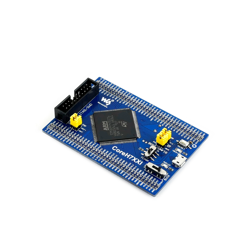
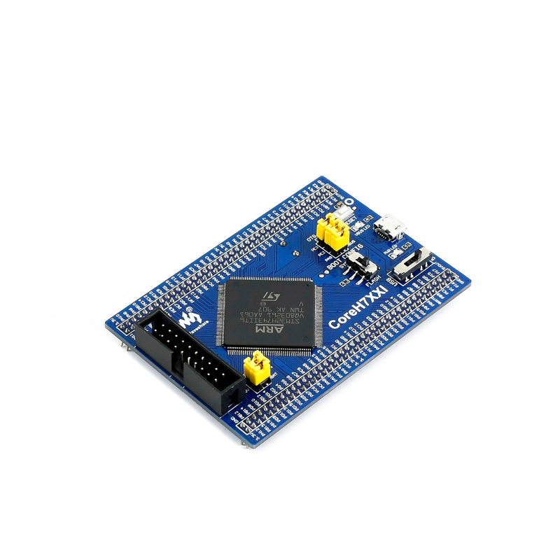
CoreH743I is an STM32 MCU core board designed for STM32H743IIT6, supports further expansion. It is ideal for starting application development with STM32H family.
Overview
CoreH743I is an STM32 MCU core board designed for STM32H743IIT6, supports further expansion. It is ideal for starting application development with STM32H family.
- Minimal ready-to-run system, integrates clock circuit, USB power management, USB connector, etc.
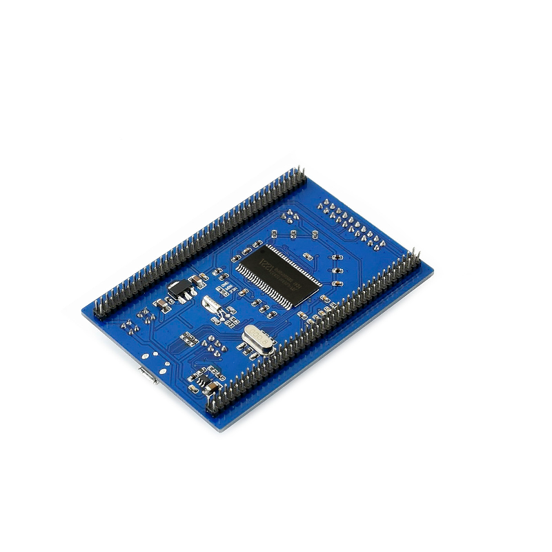
- Onboard 64M Bit SDRAM
- All the I/O ports are accessible on the pin headers
- JTAG/SWD programming/debugging interface
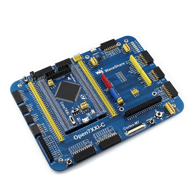
- 2.0mm header pitch, allowed to be plugged-in your application board
What's on the CoreH743I

- STM32H743IIT6:the high performance STM32 MCU which features:
- Core: Cortex-M7 32-bit RISC + double-precision FPU + Chrom-ART graphic accelerator
- Feature: single-cycle DSP instructions
- Operating Frequency: 480MHz, 1027 DMIPS / 2.14 DMIPS/MHz
- Operating Voltage: 1.62V-3.6V
- Package: LQFP176
- Memories: 2MB Flash, 1MB RAM (864KB User+192KB TCM+4KB Backup)
- MCU communication Interfaces:
- 6 x SPI, 4 x USART, 4 x UART, 1 x LPUART, 3 x I2S
- 4 x I2C, 2 x FDCAN, 1 x QUAD-SPI, 1 x DCMI, 4 x SAI
- 1 x FMC, 2 x SDMMC, 10 x TIM , 5 x LPTIM
- 1 x LTDC, 1 x SPDIFRX, 1 x HDMI-CEC, 1 x SWPMI
- 2 x COMP, 2 x OPAMP, 1 x HRTIM, 1 x RNG, 1 x DM2D, 1 x MDIO, 1 x SysTick
- 1 x USB 2.0 OTG FS
- 1 x USB 2.0 OTG HS (supports external HS PHY through ULPI)
- 1 x 10/100 Ethernet MAC
- AD & DA converters: 3 x AD (16-bit); 2 x DA (12-bit)
- Debugging/Programming: supports JTAG/SWD interfaces, supports IAP
- IC42S16400J / IS42S16400J: SDRAM 1 Meg Bits x 16 Bits x 4 Banks (64-MBIT)
- STMPS2151STR: onboard USB power management device
- AMS1117-3.3: 3.3V voltage regulator
- 8M crystal
- 32.768K crystal, for internal RTC with calibration
- Reset button
- VBUS LED: USB port indicator
- PWR LED: Power indicator
- Power supply switch, powered from 5Vin or USB connection
- Boot mode selection, for configuring BOOT0 pin
- JTAG/SWD interface: for debugging/programming
- USB connector, supports Device and/or Host
- MCU pins expander, VCC, GND and all the I/O pins are accessible on expansion connectors for further expansion
- POWER jumper
- VBAT: short the jumper to use system power supply, open it to connect external power, such as battery
- VREF: short the jumper to connect VREF+ to VCC, open it to connect VREF+ to other custom pin via jumper wire
- OTG jumper
- short the jumper when using USB OTG/HOST
- open the jumper to disconnect from related I/O port
Note: CoreH743I provides JTAG/SWD debugging interface, yet does NOT integrate any debugging function, a debugger is required.
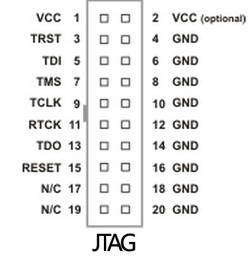
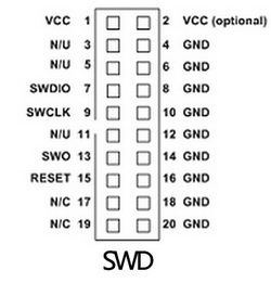
JTAG/SWD interfaces
The figure 1, and 2 show the header pinouts of JTAG/SWD interface
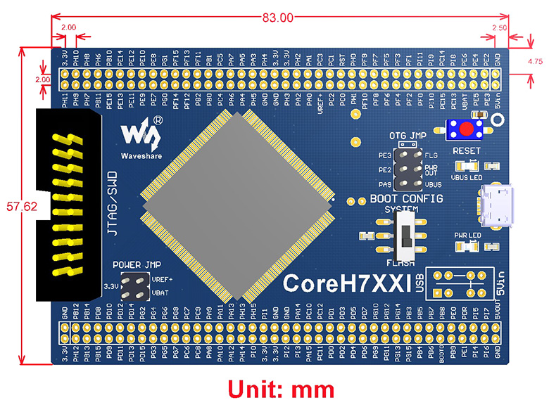
Dimensions
TAG:
RISC V
Pi5 Active Cooler Silver
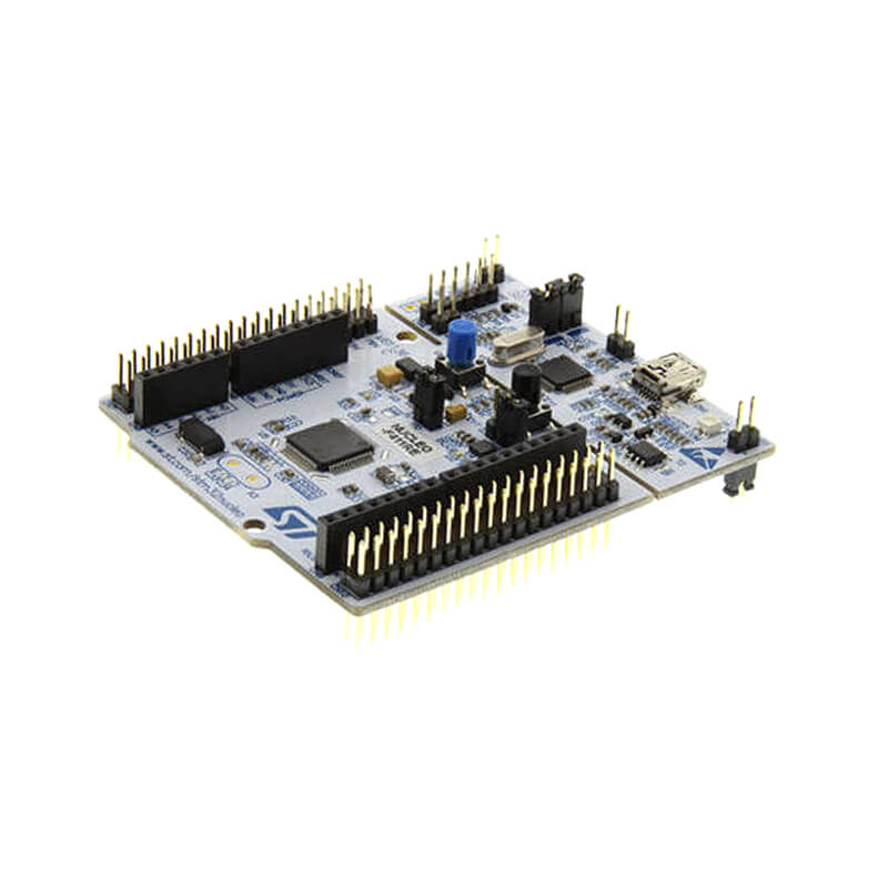
NUCLEO
Raspberry Pi Camera
ESP32-C6
Modbus RTU CAN
RS232 to RJ45
ESP32-C6 WiFi 6 ESP32-C6-Zero Super-Mini ESP32-C6FH4 WiFi 6 Bluetooth 5
ESP32-S3-Zero
Raspberry Pi
HDMI to RGB
Cortex-A53
D500
3D Display Transparent Screen
Argon Neo 5
Jetson 1.5inch LCD
USB CAN Analyzer
Milk-V Duo Agency
Pi5 Pure-Copper Active Cooler
360° Sensor
Forum: