- sales/support
Google Chat: zj734465502@gmail.com
- sales
+86-0755-88291180
- sales01
sales01@spotpear.com
- sales02
dragon_manager@163.com
- support
services01@spotpear.com
- CEO-Complaints
manager01@spotpear.com
- sales/support
WhatsApp:13246739196
Raspberry Pi CM4-IO-BASE-A User Guide
Overview
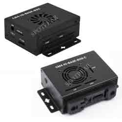
Mini Base Board (A) Designed For Raspberry Pi Compute Module 4
Release Notes
Version: CM4-IO-BASE-A V4
 1: Fix the inconsistency between BT-DIS and WIFI-DIS silk screen and actual pins

 2: DSI interface is changed from DSI0 to DSI1, high resolution is supported
Version: CM4-IO-BASE-A V3.1
 1: Fix the problem that some CM4 cannot be restarted

 2: The power supply scheme is modified to improve the output capacity.
Note
1: DO NOT unplug any devices other than HDMI and USB when powering on.
2: FAN only supports 5V, and 12V is not supported. Confirm the fan voltage before connecting. This version of the fan does not have a controller and cannot be adjusted in speed.
3: The DSI display interface is the DSI0 interface, and the DSI1 display interface is not connected. (V4 version starts to display interface for DSI1)
4: Type C interface can be used for the power supply or a USB SLAVE interface for programming images.
5: In order to ensure the normal power supply of CM4, please do not connect other devices when using the Type C interface to burn the image.
6: When CM4 is in normal use, it needs to provide 5V/2A power supply for CM4. Otherwise, problems such as automatic shutdown, frequency reduction, etc. may occur.
7: When using the M.2 interface, please use the matching screws. Using screws of other lengths may cause the CM4 core to be damaged by the screws.
8: The module does not have any protection, please do not short-circuit the power supply.
9: USB2.0 is closed by default, if you need to open it, you need to add dtoverlay=dwc2,dr_mode=host.
10: If you want to use HDMI1 alone, you can purchase it separately if you need to use it HDMI Adapter.
11: Both USB 3/4 and HDMI1 need to be used, you can use adapter board to connect it out.
12: This expansion board does not support the POE function.
13: M.2 interface power supply is limited to 1.5A, if it causes problems such as slowing down of solid state or other equipment, it is recommended to buy version B.(V3 version has been fixed)
What's on board
| No. | Component | Description |
| 1 | CM4 connector | Suitable for all versions of Compute Module 4 |
| 2 | DC power supply/programming interface | 5V/2.5A power supply, also can be used as eMMC programming interface |
| 3 | DISP Interface | MIPI DSI Display interface |
| 4 | FAN Interface | For connecting cooling fan, allows speed adjustment and measuremen, only support 5V fan. |
| 5 | CAM Interface | Dual MIPI CSI camera interface |
| 6 | HDMI0 Interface | HDMI Interface,Support 4K 30fps output |
| 7 | USB 2.0 Interface | 2-channel USB 2.0 Interface, for connecting sorts of USB devices |
| 8 | Gigabit Ethernet | Gigabit Ethernet RJ45 connector, with 10 / 100 / 1000M network support |
| 9 | M.2 indicators | Indicating the operating status of M.2 interface |
| 10 | ACT indicators | Raspberry Pi operating status indicator |
| 11 | PWR indicators | Raspberry Pi power indicator |
| 12 | BOOT selection | jumper shorted: CM4 would be booted from USB-C interface jumper opened: CM4 would be booted from eMMC or Micro SD card |
| 13 | 40PIN GPIO Interface | Conveniently connect various HAT modules |
| 14 | Micro SD Card interface | For connecting a Micro SD card with pre-burnt image (Lite variant ONLY). |
| 15 | HDMI1 interface | HDMI1 Interface,Support 4K 30fps output |
| 16 | USB 2.0 interface | Can be connected through an adapter |
| 17 | FE1.1S | USB HUB chip, expanding one USB port to 4x ports |
| 18 | M.2 Interface | Supports sorts of NVME SSD, or communication modules with PCIE M.2 KEY-M interface |
Precautions
Do not plug or unplug any device while it is powered on.
Writing Image
- Write Image for Compute Module Boards eMMC version
- Write Image for Compute Module Boards Lite version
USB2.0
CM4 Error:
config failed, hub doesn't have any ports! (err -19)
However, the USB can still be used. If you want to remove this error, remove "otg_mode=1" in [cm4] of config.txt, and add "dtoverlay=dwc2, dr_mode=host" (USB cannot be recognized without adding it).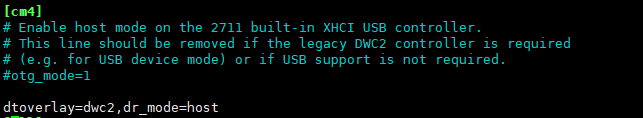
If the USB does not work, you need to add the following to the config .txt file:
dtoverlay=dwc2,dr_mode=host
Then reboot.
M.2
The M.2 interface type is M KEY, which only supports PCIE channel devices (including NVME solid state, etc.), and does not support SATA hard disks.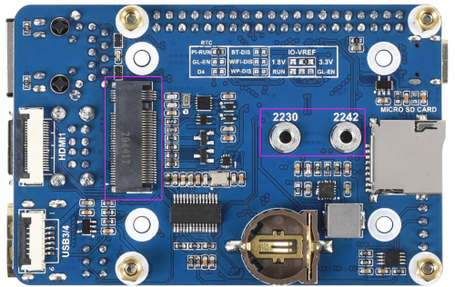
Support some type of adapter cards by using the PCIE channel. Some types of cards cannot be driven by the official Raspberry Pi image, it needs to recompile the kernel.
FAN
The PWM pin of the FAN is connected to the GPIO18 of the CM4 board.
CSI DSI
The V4 version starts to use the DSI1 interface, select the corresponding command when compiling the corresponding file.
Config File
CSI and DSI are disabled by default. When using the camera and DSI, it will occupy three I2C devices: I2C-10, I2C-11, and I2C-0.
- Open a terminal and run the following commands:
wget https://www.waveshare.com/w/upload/7/75/CM4_dt_blob_Source.zip
 unzip -o  CM4_dt_blob_Source.zip -d ./CM4_dt_blob_Source
 sudo chmod 777 -R CM4_dt_blob_Source
 cd CM4_dt_blob_Source/
 #If you want to use two cameras and DSI0, please execute
 sudo  dtc -I dts -O dtb -o /boot/dt-blob.bin dt-blob-disp0-double_cam.dts
 #If you want to use two cameras and DSI1, please execute
 sudo  dtc -I dts -O dtb -o /boot/dt-blob.bin dt-blob-disp1-double_cam.dts
 #When using any DSI interface, HDMI1 will have no image output, even if you do not connect the DSI screen, as long as you compile the corresponding file, then HDMI1 will not output
  #If you need to restore, please delete the corresponding dt-blob.bin: sudo rm -rf /boot/dt-blob.bin
  # After execution, turn off the power and restart the CM4
Recording test
And then connect the cameras and DSI display;
1: Please power off the IO Board first before connecting.
2: Connet the power supply. 3: The screen will boot up after waiting for a few seconds. 4: If the screen cannot be booted up, please check if you have added /boot/dt-blob.bin. If there already has the dt-blob.bin, just try to reboot.
Old Version (Buster)
The camera needs to be enabled by raspi-config, choose Interfacing Options->Camera->Yes->Finish-Yes, and then reboot the system. Open "enable camera" and reboot to save the change.
- Test the RPI Cameras:
Test camera0:
sudo raspivid -t 0 -cs 0
Test camera1:
sudo raspivid -t 0 -cs 1
New Version (Bullseye)
If you are using the latest Raspberry Pi OS (Bullseye):
#Use dual cameras in the new system
#Remove camera_auto_detect=1 in config.txt
#camera_auto_detect=1

#Add
dtoverlay=imx219,cam1
dtoverlay=imx219,cam0

#Among which, imx219 is the camera sensor model, and other sensors are also supported
dtoverlay=ov5647,cam0
dtoverlay=imx219,cam0
dtoverlay=ov9281,cam0
dtoverlay=imx477,cam0
dtoverlay=imx519,cam0

#And then reboot
reboot

#Open the camera
libcamera-hello -t 0
or
libcamera-hello

#Other commands:
#Check whether the camera is detected
libcamera-hello --list-cameras

#Open the corresponding camera to preview for 5 seconds
libcamera-hello  --camera 1
libcamera-hello  --camera 0

#Take a photo
libcamera-jpeg -o test.jpg

#Record video
libcamera-vid -t 10000 -o test.h264

#Also, you can add --camera to specify the camera
#-t <duration> option allows the user to choose how long the window is displayed in milliseconds
More instructions click me
- HDMI1 is disabled if you use DSI interfaces for displaying, even if you just compile the corresponding files without connecting to the DSI screen, please note it.
- Any connection of two HDMI ports can output images, not limited to which HDMI port, if two HDMI screens are connected, only HDMI0 has image output.
- If you want to enable both HDMI, please delete the dt-blob.bin file with the following command:
sudo rm -rf /boot/dt-blob.bin
- Then reboot.
Reference Raspberry Pi Manual