- sales/support
Google Chat: zj734465502@gmail.com
- sales
+86-0755-88291180
- sales01
sales01@spotpear.com
- sales02
dragon_manager@163.com
- support
services01@spotpear.com
- CEO-Complaints
manager01@spotpear.com
- sales/support
WhatsApp:13246739196
Raspberry Pi CM4-Duino User Guide
Overview
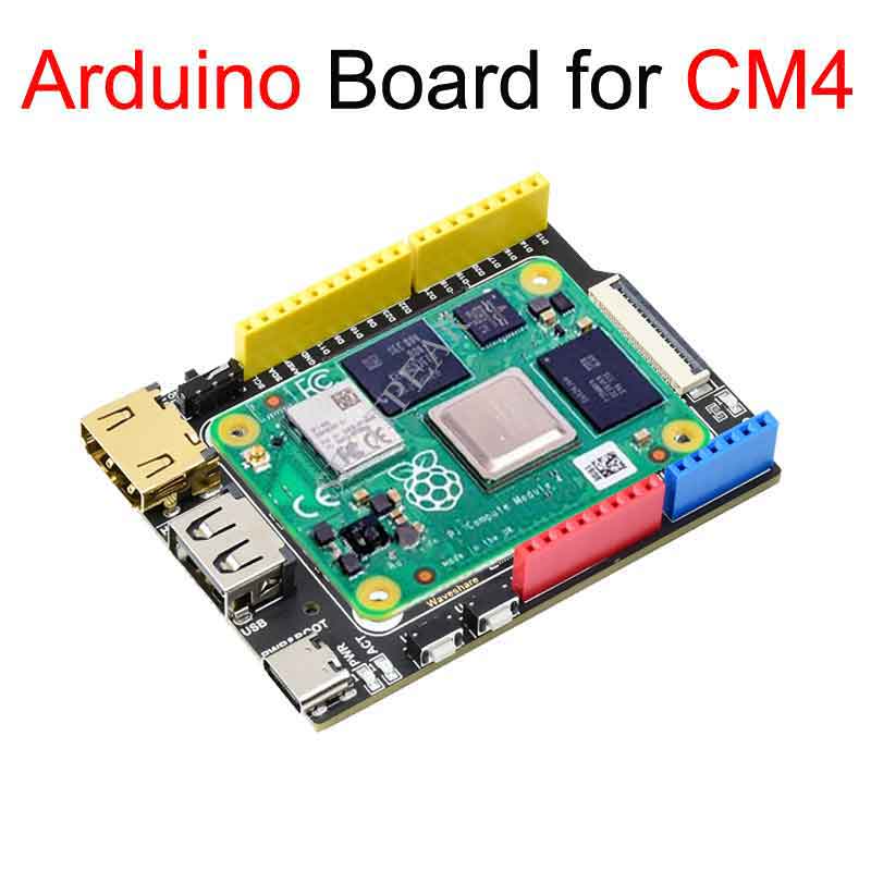
I am a CM4 duino basic expansion board, an expansion board that can be used with Raspberry Pi Compute Module 4, and supports 5V DC power supply with Typc-C interface. Onboard HDMI interface, one CSI interface and one USB interface, standard arduino interface, etc...
Precautions for use
1: Do not plug and unplug any device except USB and HDMI when powered on.
2: Type C interface can be used as power supply or as USB interface to burn image (need to use BOOT switch to switch)
3: In order to ensure the normal power supply of CM4, please do not connect other devices when using the Type C interface to burn the image.
4: When CM4 is in normal use, it needs to provide 5V 2A power supply for CM4. Otherwise, there may be problems such as automatic shutdown, frequency reduction and so on.
5: USB2.0 is closed by default, if you want to open it, you need to add dtoverlay=dwc2,dr_mode=host in config.txt
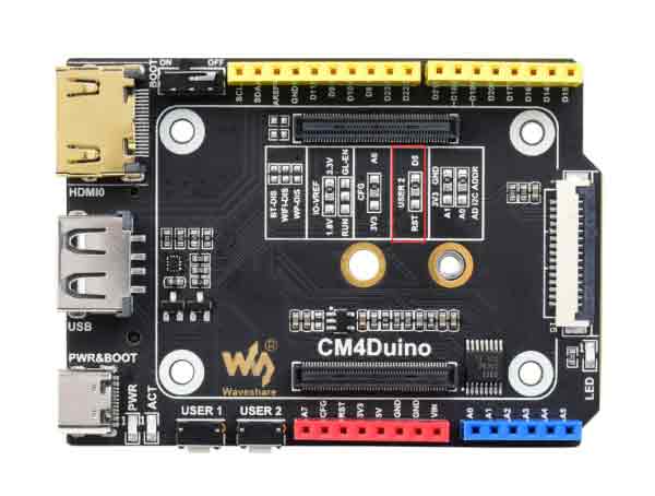
Product Size
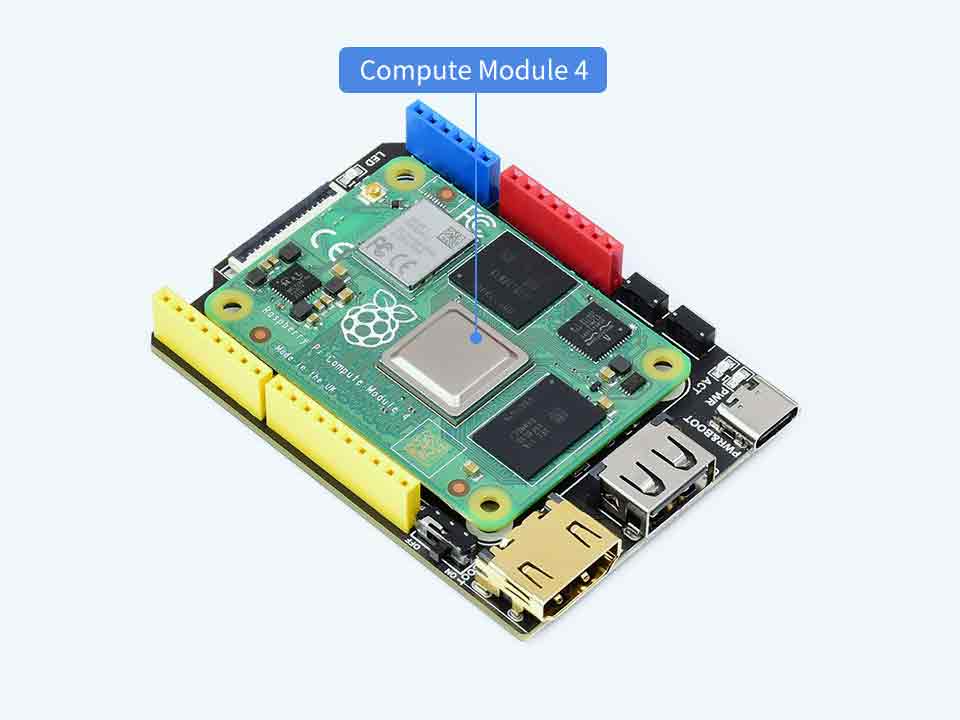
CM4-Duino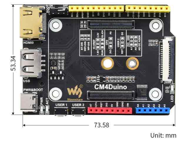
Compute_Module 4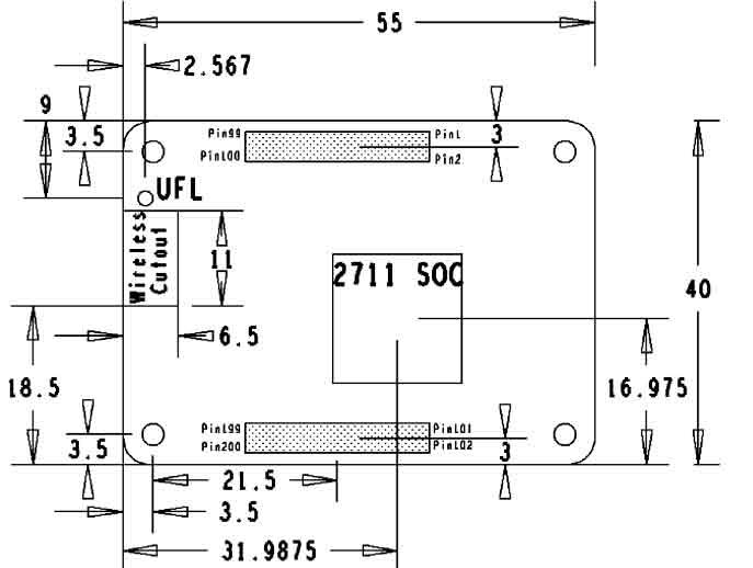
What's on board
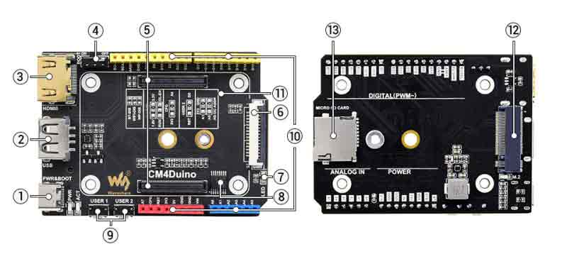
| Label | Name | Description |
| 1 | Power supply/burning interface | 5V/2A power supply, can also be used as eMMC burning interface |
| 2 | USB 2.0 interface | USB 2.0 interface, support various USB devices to be inserted |
| 3 | HDMI port | HDMI port, supports 4K 30fps output |
| 4 | BOOT switch button | ON: Compute Module 4 boots to USB Type-C port OFF: Compute Module 4 boots to eMMC or Micro SD card |
| 5 | CM4 Connector | Applies to all versions of Compute Module 4 |
| 6 | CAM Interface | MIPI CSI Camera Interface |
| 7 | User LED | LED blinks and sparkles |
| 8 | ADC chip | 8-bit ADC, I2C interface, 8-channel ADC chip ADS7830 |
| 9 | User Button | Button Module |
| 10 | GPIO | Arduino interface GPIO |
| 11 | Function Switch | For details, please refer to the function pin description |
| 12 | M.2 interface | A module that supports NVME SSD solid state or other PCIE channels |
| 13 | Micro SD card interface | For inserting a Micro SD card with the system to start the Compute Module 4 Lite |
Hardware Connection
Note
Do not plug or unplug any device while it is powered on!
Writing Image
- Write Image for Compute Module Boards eMMC version
- Wrote Image for Compute Module Boards Lite version
USB2.0
The USB port is disabled by default on the CM4 to save power. If you need to start, you need to add the following to the config.txt file:
dtoverlay=dwc2,dr_mode=host
After restarting
If you use the latest Raspberry Pi OS (image after October 30, 2021) USB2.0 is OTG mode by default, CM4 will report an error:
config failed, hub doesn't have any ports! (err -19)
However, USB can still be used. If you want to remove this error, remove otg_mode=1 in [cm4] of config.txt, and add dtoverlay=dwc2, dr_mode=host (USB cannot be recognized without adding it).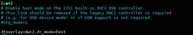
ADC
Basic introduction
The ADS7830 is a single-supply, low-power, 8-bit data acquisition device with a serial I2C interface and an 8-channel multiplexer. The analog-to-digital (A/D) converter has a track-and-hold amplifier and an internal asynchronous clock.
The ADS7830 has a resolution of 8 bits, a total of 8 inputs, and a maximum sampling rate of 70KSPS.
It can be set to differential mode and single-ended input, and the program defaults to single-ended input.
The I2C address is: 0x48
Download Program
Open the Raspberry Pi terminal and execute the following command:
sudo apt-get install p7zip-full
https://www.waveshare.com/w/upload/5/5d/CM4-duino-code.zip
7z x CM4-duino-code.zip -O./
cd CM4-duino-code
Python
Run the routine, the program supports python2/3
# python2
sudo python ADS7830.py
# python3
sudo python3 ADS7830.py
As shown in the figure below, A0-A7 are 7 analog input channels: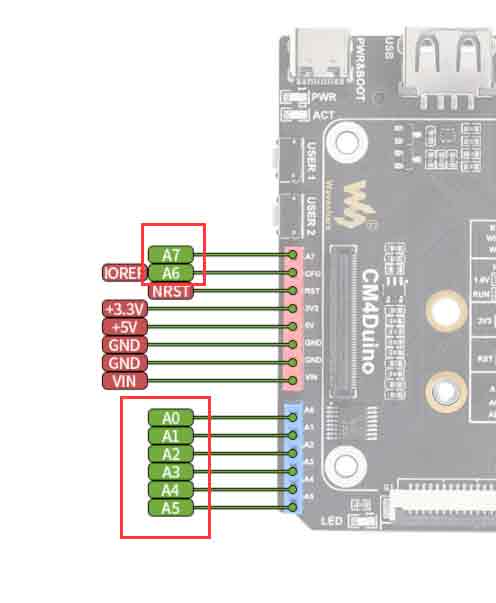
Note: A total of 8 ADCs are collected from 0-7. If the channel is suspended, the value of the channel will float up and down, and the data will be invalid;
LED usage
A programmable LED is onboard: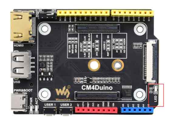
Using GPIO6 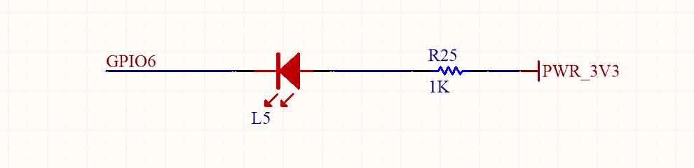
Button usage
Onboard 2 buttons USER1 USER2: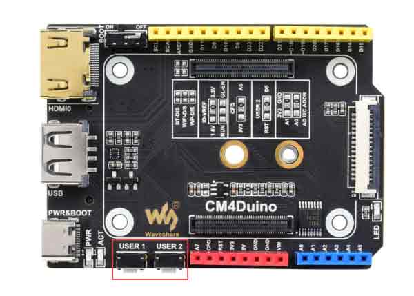
USER1 uses GPIO4, USER uses GPIO5, and USER2 can choose whether it is the reset of CM4 through the resistor, and the default connected GPIO5 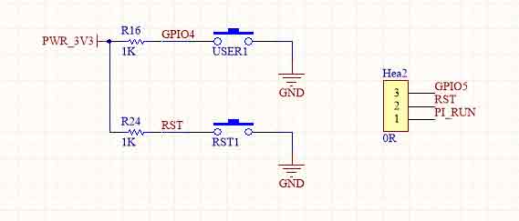
Functional pin description
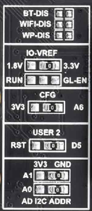
| Label | Name | Description |
| 1 | BT-DIS | Disable Bluetooth, only support core board with wireless module |
| 2 | WIFI-DIS | Disable WIFI, only support core board with wireless module |
| 3 | IO-VREF | IO logic voltage selection |
| 4 | RUN/GL-EN | Reset or shutdown CM4 |
| 5 | CFG | CFG pin function select 3.3V or A6 |
| 6 | USER | User button Function selection, D5 or RST |
| 7 | I2C ADDR | ADC function module I2C address selection, default address: 0x48 |
CSI DSI
CSI and DSI are disabled by default. I2C-10、I2C-11、I2C-0 should be used for Camera and DSI displays.
Open a terminal and run the following commands:
 sudo apt-get install p7zip-full
 wget https://www.waveshare.com/w/upload/4/41/CM4_dt_blob.7z
 7z x CM4_dt_blob.7z -O./CM4_dt_blob
 sudo chmod 777 -R CM4_dt_blob
 cd CM4_dt_blob/
 #If you want to use both cameras and DSI0
 sudo  dtc -I dts -O dtb -o /boot/dt-blob.bin dt-blob-disp0-double_cam.dts
 #If you want to ue both cameras and DSI1
 sudo  dtc -I dts -O dtb -o /boot/dt-blob.bin dt-blob-disp1-double_cam.dts
 #HDMI1 is disabled if you use DSI interfaces for displayin. HDMI1 cannot work even thought you just built the file without connecting DSI display, please note it.
 #If you want to enable the HDMI1, please remove the dt-blob.bin file with the command: '''sudo rm -rf /boot/dt-blob.bin'''
 #Turn off IO Board and re-power the CM4
Connect Cameras and DSI display
1: Please first disconnect power off the IP Board when connecting.
2: Use CM-DSI-ADAPTER to connect Compute Module 4 PoE Board and DSI displays
3: UseCSI adapter cable to connect Compute Module 4 PoE Board and CSI cameras.
3: Connect the power adapter
4: Wait for booting.
5: If the DSI display cannot work, please check if you have added /boot/dt-blob.bin and reboot.
6: Please enable camera by raspi-config, choose Interfacing Options->Camera->Yes->Finish-Yesand reboot
Reference:
Test RPi Camera:
Test video0:
sudo raspivid -t 0 -cs 0
Test video1:
sudo raspivid -t 0 -cs 1
New Version (Bullseye)
If using the latest Raspberry Pi OS (Bullseye):
#The new system uses dual cameras
#Remove camera_auto_detect=1 in config.txt
#camera_auto_detect=1

#Add to
dtoverlay=imx219,cam1
dtoverlay=imx219,cam0

#Where imx219 is the camera sensor model, and other sensors are supported
dtoverlay=ov5647,cam0
dtoverlay=imx219,cam0
dtoverlay=ov9281,cam0
dtoverlay=imx477,cam0
dtoverlay=imx519,cam0

#then restart
reboot

#open camera
libcamera-hello -t 0
or
libcamera-hello


#Other part of the command:
#Check if the camera is detected
libcamera-hello --list-cameras

#Open the corresponding camera, preview for 5 seconds
libcamera-hello --camera 1
libcamera-hello --camera 0

#taking photos
libcamera-jpeg -o test.jpg

#shoot video
libcamera-vid -t 10000 -o test.h264

#You can add --camera to specify the camera
The #-t <duration> option allows the user to choose how long the window will be displayed, in milliseconds
More instructions click me
- Note: If using the DSI interface display will have an HDMI disabled, even if just compile the corresponding file without connecting the DSI screen.
- Any connection of two HDMIs can output images, not limited to that HDMI, if two HDMI screens are connected, only HDMI0 has image output
- If you want to enable both HDMI, delete the dt-blob.bin file with the following command:
sudo rm -rf /boot/dt-blob.bin
- Then reboot
Reference Raspberry Pi Manual