


- sales/support
Google Chat: zj734465502@gmail.com
- sales
+86-0755-88291180
- sales01
sales01@spotpear.com
- sales02
dragon_manager@163.com
- support
services01@spotpear.com
- CEO-Complaints
manager01@spotpear.com
- sales/support
WhatsApp:13246739196
- HOME
- >
- ARTICLES
- >
- Common Moudle
- >
- LCD
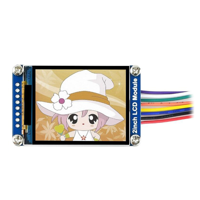
2inch LCD Module
Instruction
This is a general LCD display Module, IPS screen, 2inch diagonal, 240×320 resolution, with embedded controller, communicating via SPI interface
Feature
- SPI interface, requires minimum GPIO for controlling
- Comes with development resources and manual
Specifications
- Driver: ST7789
- Interface: SPI
- Display color: RGB, 262K color
- Resolution: 240×320
- Backlight: LED
- Operating voltage: 3.3V
Interface
| SYMBOL | Description |
| VCC | Power (3.3V input) |
| GND | Ground |
| DIN | SPI data input |
| CLK | SPI clock input |
| CS | Chip selection, low active |
| DC | Data/Command selection (high for data, low for command) |
| RST | Reset, low active |
| BL | Backlight |
Hardware description
ST7789V supports RGB444, RGB565 and RGB666 three formats. This LCD uses RGB565.
For most of the LCD controller, there are several interfaces for choosing, this module we use SPI interface which is fast and simple.
Communication protocol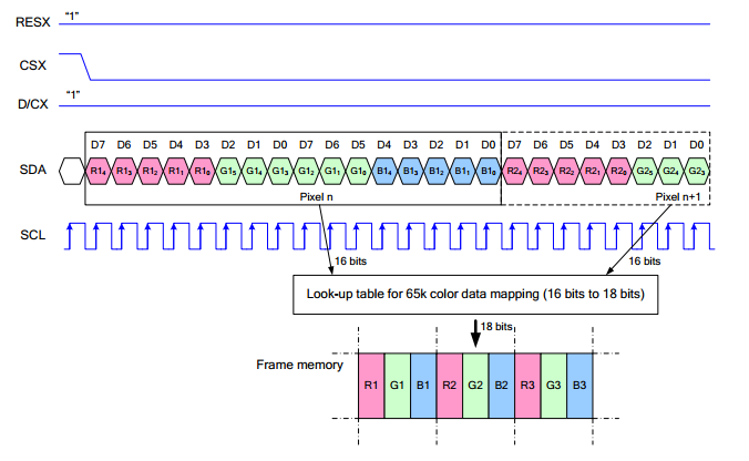
Note: It is not like the tradition SPI protocol, it only uses MOSI to send data from master to slave for LCD display. For details please refer to Datasheet Page 105.
RESX: Reset, should be pull-down when power on, set to 1 other time.
CSX: Slave chip select. The chip is enabled only CS is set Low
D/CX: Data/Command selection; DC=0, write command; DC=1, write data
SDA: Data transmitted. (RGB data)
SCL: SPI clock
The SPI communication protocol of the data transmission uses control bits: clock phase (CPHA) and clock polarity (CPOL):
CPOL defines the level while the synchronization clock is idle. If CPOL=0, then it is LOW.
CPHA defines at whish clock’s tick the data transmission starts. CPHL=0 – at the first one, otherwise at the second one
This combination of two bits provides 4 modes of SPI data transmission. The commonly used is SPI0 mode, i.e. GPHL=0 and CPOL=0.
According to the figure above, data transmitting begins at the first falling edge, 8bit data are transmitted at one clock cycle. It is SPI0. MSB.
Raspberry Pi examples
For Raspberry Pi we provide examples based on C and python
Enable SPI
Open terminal and run commands to enable SPI interface
sudo raspi-config
Choose Interfacing Options -> SPI -> Yes
Then reboot Raspberry Pi
Libraries installation
- BCM2835
wget http://www.airspayce.com/mikem/bcm2835/bcm2835-1.60.tar.gz
tar zxvf bcm2835-1.60.tar.gz
cd bcm2835-1.60/
sudo ./configure
sudo make
sudo make check
sudo make install
- WiringPi
sudo apt-get install wiringpi
cd /tmp
wget https://project-downloads.drogon.net/wiringpi-latest.deb
sudo dpkg -i wiringpi-latest.deb
gpio -v
- Python2
sudo apt-get updata
sudo apt-get install python-pip
sudo pip install RPi.GPIO
sudo pip install spidev
sudo apt-get install python-imaging
- Python3
sudo apt-get update
sudo apt-get install python3-pip
sudo pip3 install RPi.GPIO
sudo pip3 install spidev
sudo apt-get install python3-imaging
Hardware connection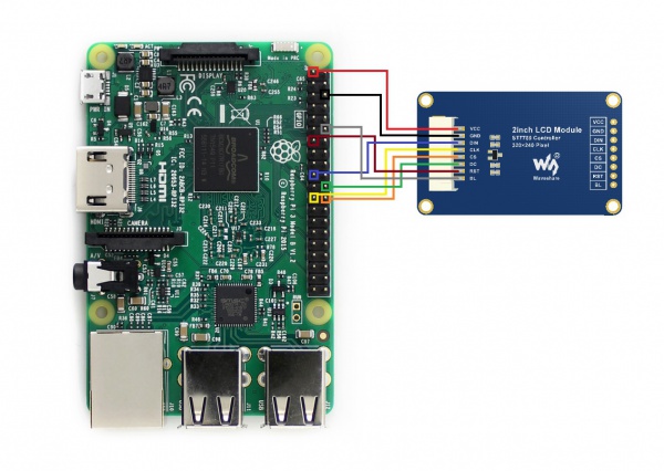
Please notice, that wires colors may vary. Use pins designations for wiring.
| 2inch LCD | Board number | BCM number |
| VCC | 3.3V | 3.3V |
| GND | GND | GND |
| DIN | 19 | MOSI |
| CLK | 23 | SCLK |
| CS | 24 | CE0 |
| DC | 22 | P25 |
| RST | 13 | P27 |
| BL | 12 | P18 |
Download examples
Open terminal and download examples
sudo apt-get install p7zip-full
wget http://www.waveshare.net/w/upload/1/19/2inch_LCD_Module_code.7z
7z x 2inch_LCD_Module_code.7z  -r -o./2inch_LCD_Module_code
sudo chmod 777 -R  2inch_LCD_Module_code
cd 2inch_LCD_Module_code/RaspberryPi\&JetsonNano/
Test examples
- C codes
cd c
sudo make clean
sudo make
sudo ./main
- Python codes
cd python/examples
sudo python main.py
Expected result
- The display is cleaned to white
- Display numbers and strings
- Draw a rectangle
- Draw a line
- Draw five circles
- Display a 100x100 image
- display a 240x320 image
STM32 examples
- Download the demo codes from Waveshare wiki, the path of STM32 codes is ~/STM32/
- Open the project from \XNUCLEO-F103RB\MDK-ARM\ with Keil software. Note that the codes are based on HAL libraries.
- The development board we use is WaveshareXNUCLEO-F103RB
Hardware connection
| 2inch LCD | XNUCLEO-F103RB |
| VCC | 5V |
| GND | GND |
| DIN | PA7 |
| CLK | PA5 |
| CS | PB6 |
| DC | PA8 |
| RST | PA9 |
| BL | PC7 |
Expected result
- The display is cleaned to white
- Display numbers and strings
- Draw a rectangle
- Draw a line
- Draw five circles
- Display a 70x70 image
Arduino
- Download examples from wiki. Unzip it. The path of Arduino examples is ~/Arduino UNO/...
- Copyt the folders in Arduino directory to 【Installation directory】/libraries/ (Generally the installation directory is C:\Program Files (x86)\Arduino\libraries)
- Open Arduino IDE software, and click File -> Examples to check if LCD_2inch codes are there.
- The development board used is Arduino UNO.
Hardware connection
| 2inch LCD | UNO PLUS |
| VCC | 5V |
| GND | GND |
| DIN | D11 |
| CLK | D12 |
| CS | D10 |
| DC | D7 |
| RST | D8 |
| BL | D9 |
Expected result
- The display is cleaned to white
- Display numbers and strings
- Draw a rectangle
- Draw a line
- Draw five circles
- Display a 70x70 image