


- sales/support
Google Chat: zj734465502@gmail.com
- sales
+86-0755-88291180
- sales01
sales01@spotpear.com
- sales02
dragon_manager@163.com
- support
services01@spotpear.com
- CEO-Complaints
manager01@spotpear.com
- sales/support
WhatsApp:13246739196
- HOME
- >
- ARTICLES
- >
- Common Moudle
- >
- UART Module
Modbus POE ETH Relay User Guide
Resource
Demo
Software
- VirCom: Configuration Software
- Virtual serial port: Serial port driver
- Sscom5.13.1_for_Modbus_POE_ETH_Relay: Sscom software
Overview
Hardware Description
Hardware Connection
- Connects Modbus POE ETH Relay to the LAN via a network cable, powered through the power port or via POE.
- Note: The above picture is using a PoE port for power supply. If the network cable you used is a normal one, you need to connect an external power adapter to supply power in the range of 7~36V.
Indicator Note
Indicator Status Description RUN Ethernet operation indicator. After the chip is working properly, it will output a square wave with a period of 2 seconds. STA MCU indicator, blinking when the MCU is operating normally. TXD Send indicator, light is on when sending data. RXD Receive indicator, light is on when receiving data. Ethernet Port Green Light The green light is on when a TCP connection is established and can be used to determine if the module has established a communication link with the host computer software. Ethernet Port Yellow Light Data transmission light, when there is data transmission on the network port, the yellow light transition state will change, which can be used to determine whether there is data transmission. Software Installation
Vircom can be used for configuring device IP and other parameters, as well as creating virtual serial ports. If the virtual serial port functionality is not needed, you can simply download the installation-free version of the configuration software.
- VirCom: Configuration Software
- Virtual serial port: Serial port driver
- Sscom5.13.1_for_Modbus_POE_ETH_Relay: Sscom software
Driver installation requires decompression, double-click the software to install, if the virtual serial port in Vircom is not displayed, then reboot and check again.
Example
TCP Communication Test
Software Preparation
- VirCom: Configuration Software
- Sscom5.13.1_for_Modbus_POE_ETH_Relay: Sscom software
Host Computer Setting
After connecting to the Modbus POE ETH Relay, connect it to the network. Run the Vircom software, (The computer on which Vircom is installed must be on the same LAN as the module.).
The operation is shown below:- ① Click
Device Management - ② Click
Auto-search - ③ Software search recognizes Modbus POE ETH Relay devices connected to the LAN.
- ④ Select the device, and then click
Editor directly double click the searched device. - ⑤ Set up the device parameters.
- Click the "Local IP" button to identify the computer's IP address, change the "IP Address" to a static address, and note that the static IP address entered is not used by other devices and needs to be on the same LAN as the computer.
- Click the "Local IP" button to identify the computer's IP address, change the "IP Address" to a static address, and note that the static IP address entered is not used by other devices and needs to be on the same LAN as the computer.
- The operating mode is TCP server. The serial port setting defaults to 115200 and cannot be modified.
- The "Convert Protocol" in the
Advanced option, the default setting is "None", that is, you select modbus rtu protocol. If you use Modbus_TCP protocol, you can select "modbus tcp protocol".
- The operating mode is TCP server. The serial port setting defaults to 115200 and cannot be modified.
- ⑥ After setting, click
Modify Setting. - ⑦ Click
Restart. After restarting the module, the new setting takes effect.
As shown below:
File:Modbus-POE-ETH-Relay-Vircom-setting-cn.jpg- The last step is to click "Modify Setting" to save and take effect.
TCP Communication Test
- Open the serial debugging assistant window, select TCPClient for the port number, modify the remote IP and port number according to the above Vircom settings, click the "Connect" button to connect to the TCP server, the green light of the network port will light up after successful connection.
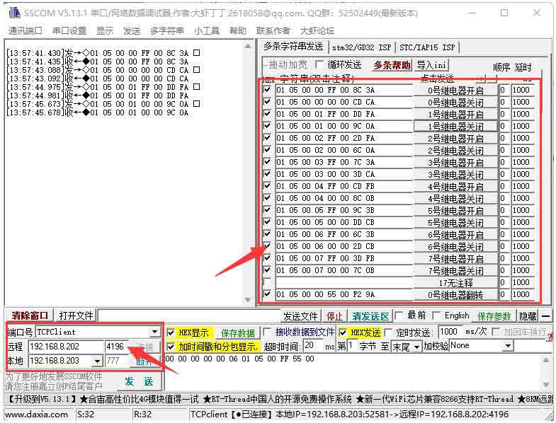
- Clicking on multiple strings will open multiple string-sending windows, and clicking on the corresponding functions will send the corresponding commands.
- Please refer to the development agreement for detailed control instructions.
- Click on "Add" and select to add COM2. Note that COM5 is a COM port that does not exist on the computer originally.
- After that, go to the device management and double-click on the device that needs to be bound to COM2. As shown in the diagram, select COM2 from the "Virtual Serial Port" list in the top left corner. Then click on "Modify Settings" and then click on "Restart Device".
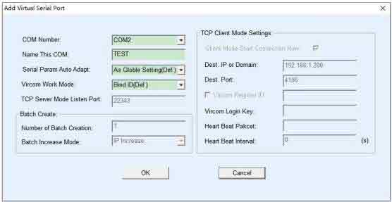
- Return to the main Vircom interface. You can see that COM2 is already connected to the device with IP 192.168.1.200. At this point, you can use COM2 to communicate instead of SSCOM2.
 Open it on your computer, open the corresponding port number, set the baud rate to 115200, click Multi-String to open the Multi-String Send window, and click the corresponding function to send the corresponding command.
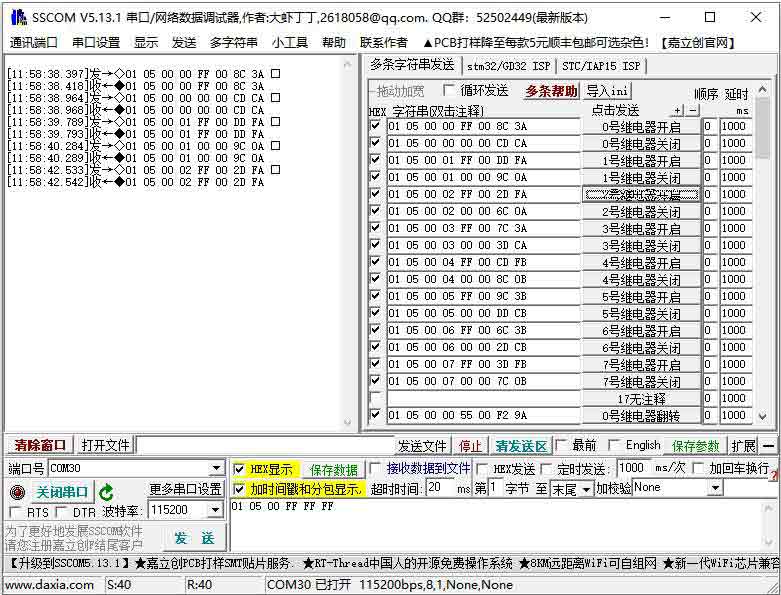
MODBUS TCP Test
By default, data is transparently transmitted using the Modbus RTU protocol. If you need to implement Modbus TCP to RTU conversion, you need to select the conversion protocol as "Modbus TCP Protocol" in the device settings dialog, as shown in the diagram below. In this case, the device port automatically changes to 502. Users can connect their Modbus TCP tool to the IP of the serial port server on port 502, and the Modbus TCP commands they send will be converted to RTU commands and outputted through the serial port.
For example, if the server's Ethernet port receives a Modbus TCP command of 00 00 00 00 00 06 01 05 00 00 FF 00 (to turn on the first relay), the host controller will receive the Modbus RTU command of 01 05 00 00 FF 00 8C 3A.

- Click on "More advanced options..." Select the Modbus gateway type as a non-storage Modbus gateway.
- Open the Sscom software, click on the Import ini button in the Multiple String Sender column, and select the Modbus tcp.ini file to import.
Virtual Serial Port Testing
The SSCOM2 in the diagram communicates directly with the TCP and serial port server. In order to allow users to communicate with the serial port server using their existing serial port software, a virtual serial port needs to be added between the user program and the serial port server. As shown in the diagram, Vircom and the user program run on the same computer. Vircom virtualizes a COM port that corresponds to the serial port server. When the user program opens the COM communication, it can send data to the user's serial port device through the Vircom serial port server. The following steps demonstrate this operation:
Click on "Serial Port Management" on the Vircom main interface.Note: The default Modbus gateway type is storage type, which will automatically send query commands several times, which may cause the master chip not to respond, and the query commands will not be affected. Therefore, you need to set it as a non-storage Modbus gateway.
File:Modbus poe eth relay 4.pngIf the error "A component named HEX0 already exists" is displayed, close the software and reopen it. Then close the software and reopen it, then re-import the file.
After successful import, the following is displayed, click on the corresponding function to send the corresponding command.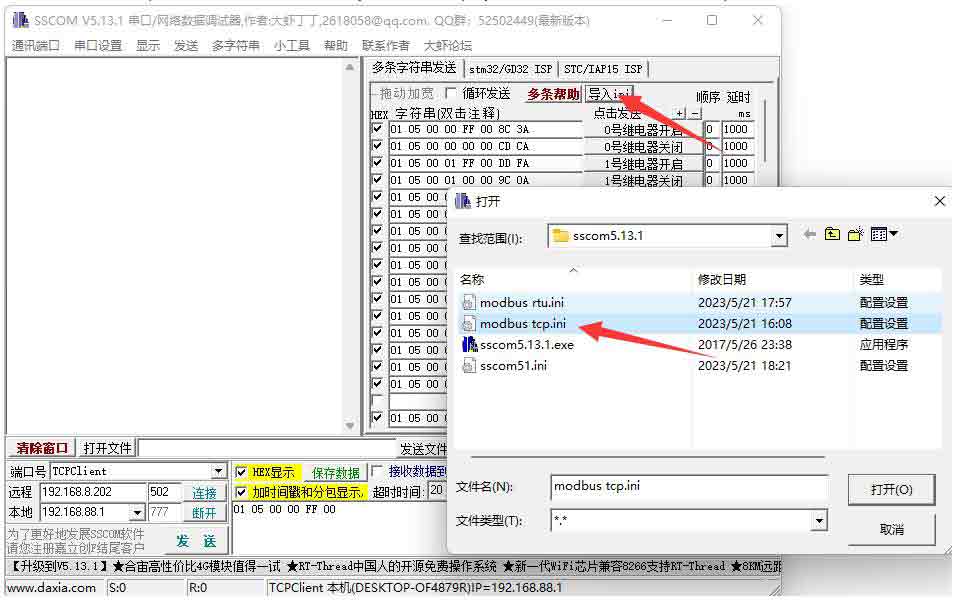

- Please refer to the Modbus TCP protocol section later for more details on Modbus TCP conversion.
WEB Configuration
Using Vircom, you can search and configure device parameters in different network segments. For Web configuration, you must first ensure that the computer and the serial server are in the same IP segment, and you need to know the IP address of the serial server in advance. But web configuration can be done on any computer without Vircom.
2. Enter a password in Password: There is no login password set by default in the factory, you can enter a password at will, and click the Login button to log in. After setting the password to log in, the settings at "Modify webpage login password" will take effect:
1. Enter the IP address of the serial server in the browser, such as http://192.168.1.200
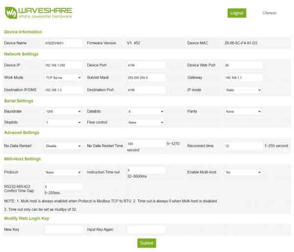 3. The serial server parameters can be modified on the web page that appears. For the relevant parameters, please refer to Table 4 for the meaning of the parameters.
4. After modifying the parameters, click the "Submit" button.
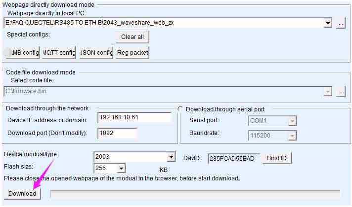
5. If the configuration web page files are overwritten during the configuration and downloading of MQTT and Jetson Modbus firmware, causing the configuration web page to be inaccessible, please follow these steps to re-download the web page files:- Configuration Interface Web Files to Modbus POE ETH Relay.
- For more details, please refer to User Manual
Demo Example
Raspberry Pi
Connect the Raspberry Pi and the ModBus POE ETHG Relay module to the same LAN.
Open the Raspberry Pi terminal and run the program by entering the following command.sudo apt-get install unzip wget https://www.waveshare.com/w/upload/e/e0/Modbus_POE_ETH_Relay_Code.zip unzip Modbus_POE_ETH_Relay_Code.zip cd Modbus_POE_ETH_Relay_Code #modbus rtu protocol vi modbus_rtu.py #Change the IP address and port number according to the actual situation sudo python3 modbus_rtu.py #modbus tcp protocol vi modbus_tcp.py #Change the IP address and port number according to the actual situation sudo python3 modbus_tcp.py
Note: To run this demo, you need to modify the demo file to change the IP address and port number to the actual IP address and port number of the ModBus POE ETHG Relay.
Modbus RTU Development Protocol
Function Code Introduction
Function Code Note 01 Read relay status 03 Read the address and version 05 Write a single relay 06 Set baud rate and address 0F Write all relays Single Relay Control
Sending Code: 01 05 00 00 FF 00 8C 3A
Fields Meaning Remarks 01 Device Address Fixed 0x01 05 05 command Control the relay command 00 00 Address Control the register address of the relay, 0x00 - 0x0008 FF 00 Command 0xFF00: relay on;
0x0000: relay off;
0x5500: relay flip8C 3A CRC16 CRC16 checksum of the first 6 bytes of data Return code: 01 05 00 00 FF 00 8C 3A
Field Meaning Remarks 01 Device Address Fixed 0x01 05 05 command Control the relay commands 00 00 Address Control the register address of the relay: 0x0000-0x0008 FF 00 Command 0xFF00: relay on;
0x0000: relay off;
0x5500: relay flip8C 3A CRC16 CRC16 checksum of the first 6 bytes of data For example:
[No. 1 address device]:
No. 0 relay on: 01 05 00 00 FF 00 8C 3A
No. 0 relay off: 01 05 00 00 00 00 CD CA
No. 1 relay on: 01 05 00 01 FF 00 DD FA
No. 1 relay off: 01 05 00 01 00 00 9C 0A
No. 2 relay on: 01 05 00 02 FF 00 2D FA
No. 2 relay off: 01 05 00 02 00 00 6C 0A
No. 3 relay on: 01 05 00 03 FF 00 7C 3A
No. 3 relay off: 01 05 00 03 00 00 3D CA
No. 0 relay flip: 01 05 00 00 55 00 F2 9A
No. 1 relay flip: 01 05 00 01 55 00 A3 5A
No. 2 relay flip: 01 05 00 02 55 00 53 5A
No. 3 relay flip: 01 05 00 03 55 00 02 9AControl All Relays
Sending code: 01 05 00 FF FF 00 BC 0A
Fields Meaning Note 01 Device Address Fixed 0x01 05 05 command Control relay commands 00 FF Address Fixed 0x00FF FF 00 Command 0xFF00: Relay on
0x0000: Relay off
0x5500: Relay flipBC 0A CRC16 CRC16 checksum of the first 6 bytes of data Return code: 01 05 00 FF FF 00 BC 0A
Fields Meaning Code 01 Device Address Fixed 0x01 05 05 command Control the relay commands 00 FF Address Fixed 0x00FF FF 00 Commands 0xFF00: relay on
0x0000: relay off
0x5500: relay flipBC 0A CRC16 CRC16 checksum of the first 6 bytes of data For example:
[No. 1 address device]:
All relays on: 01 05 00 FF FF 00 BC 0A
All relays off: 01 05 00 FF 00 00 FD FA
All relays flip: 01 05 00 FF 55 00 C2 AARead the Relay Status
Sending code: 01 01 00 00 00 08 3D CC
Fields Meaning Note 01 Device address Fixed 0x01 01 01 command Query Relay Status Command 00 00 Relay start address Fixed 0x0000 00 10 Relay numbers Fixed 0x0008 3D C6 CRC16 CRC16 checksum of the first 6 bytes of data Return code: 01 01 01 00 51 88
Field Meaning Note 01 Device address Fixed 0x01 01 01 command Query Relay Status Command 02 Number of bytes Returns all bytes of the status information 00 Status of the query Returned relay status
Bit0: the first relay status;
Bit1:the second relay status;
Bit2: the third relay status;
……
Bit15: the 8th relay status.8C 35 CRC16 CRC16 checksum of the first 6 bytes of data For example:
[NO.1 address device]
Send: 01 01 00 00 00 08 3D CC
Return: 01 01 01 00 51 88 //All relays off
Send: 01 01 00 00 00 08 3D CC
Return: 01 01 01 01 90 48 //Relay 0 is on, the rest of the relays are off.
Send: 01 01 00 00 00 08 3D CC
Return: 01 01 01 41 91 B8 //Relays 0 and 6 are on, the rest are offWrite Relay Status
Sending code: 01 0F 00 00 00 08 01 FF BE D5
Field Meaning Note 01 Device address Fixed 0x01 0F 0F command Write relay status command 00 00 Relay start address Fixed 0x0000 00 08 Relay numbers Fixed 0x0008 01 Byte count Fixed 0x01 FF Relay status Bit0: Control the first relay;
Bit1: control the second relay;
Bit2: control the third relay;
……
Bit15: control the 8th relayBE D5 CRC16 CRC16 checksum of the first 6 bytes of data Return code: 01 0F 00 00 00 01 94 0B
Field Meaning Note 01 Device address Fixed 0x01 0F 0F command All rregister control commands 00 00 Address Fixed 0x0000 00 08 Relay numbers Fixed 0x0008 54 0D CRC16 CRC16 checksum of the first 6 bytes of data For example:
[No.1 address device]
All relays on: 01 0F 00 00 00 08 01 FF BE D5
All relays off: 01 0F 00 00 00 08 01 00 FE 95
0-1 ON; 3-15 OFF: 01 0F 00 00 00 08 01 03 BE 94Relay Flash On and Flash Off Command
Sending code: 01 05 02 00 00 07 8D B0
Field Meaning Note 01 Device Address Fixed 0x01 05 05 Command Single control demmand 02 Command 02 is the command for flashing on, 04 is the command for flashing off 00 Relay Address The address of the relay to be controlled: 0x00~0x08 00 07 Interval Time Delay time for data *100ms
Value: 0x0007, Delay:7*100MS = 700MS8D B0 CRC16 CRC16 checksum of the first 6 bytes of data Return code: 01 05 02 00 00 07 8D B0
Field Meaning Note 01 Device Address Fixed 0x01 05 05 Command Single control command 02 Command 02 is the command for flashing on, 04 is the command for flashing off 00 Relay Address The address of the relay to be controlled: 0x00~0x08 00 07 Interval Time Delay time for data*100ms
Value:0x0007, delay:7*100MS = 700MS8D B0 CRC16 CRC16 checksum of the first 6 bytes of data Note:
The maximum setting for the flash on/flash off time is 0x7FFF.
For example:
[No.1 address device]
Relay 0 flashes on: 01 05 02 00 00 07 8D B0 //700MS = 7*100MS = 700MS
Relay 1 flashes on: 01 05 02 01 00 08 9C 74 //800MS
Relay 0 flashes off: 01 05 04 00 00 05 0C F9 //500MS
Relay 1 flashes off: 01 05 04 01 00 06 1D 38 //600MSRead the Device Address Command
Sending code: 00 03 40 00 00 01 90 1B
Field Meaning Note 00 Device address Fixed 0x01 03 03 command Read the device address command 40 00 Command register 0x0200 is to read the software version, 0x0040 is to read the device address 00 01 Bytes number Fixed 0x0001 90 1B CRC16 CRC16 checksum of the first 6 bytes of data Return code: 01 03 02 00 01 79 84
Field Meaning Note 00 Device address Fixed 0x01 03 03 command Read software version, read device address command 02 Byte number Return the number of bytes 00 01 Device address Set device address, fixed 0x01 79 84 CRC16 CRC16 checksum of the first 6 bytes of data For example:
[NO.1 address device]
Sending: 00 03 40 00 00 01 90 1B
Return: 01 03 02 00 01 79 84 //address 0x01Read Software Version Command
Sending code: 00 03 80 00 00 01 AC 1B
Field Meaning Note 01 Device Address 0x00 indicates the broadcast address; 0x01-0xFF indicates the device address 03 03 Command Read software version, read device address command 80 00 Command register 0x4000 is to read the device address, 0x8000 is to read the software version 00 01 Byte number Fixed 0x0001 8F CA CRC16 CRC16 checksum of the first 6 bytes of data Return code: 01 03 02 00 64 B9 AF
Field Meaning Note 01 Device Address 0x00 indicates the broadcast address; 0x01-0xFF indicates the device address 03 03 Command read the software version and the device address commands 02 Byte number Return code 00 64 Software version Convert to decimal and move the decimal point two places to the left to indicate the software version
0x0064 = 100 = V1.00B9 AF CRC16 CRC16 checksum of the first 6 bytes of data For example:
Sending: 00 03 80 00 00 01 AC 1B
Return: 01 03 02 00 64 B9 AF //0x0064 = 100 =V1.00Modbus TCP Development Protocol
Here is a brief introduction to modbus tcp and modbus rtu protocol conversion using the above command to open the first relay as an example.
- Modbus RTU command: 01 05 00 00 FF 00 8C 3A
Field Meaning Note 01 Device address Fixed 0x01 05 05 command Control relay commands 00 00 Address Address of the register to control the relay, 0x00, i.e. the first relay FF 00 Command 0xFF00: Relay on 8C 3A CRC16 CRC16 checksum of the first 6 bytes of data - Modbus TCP command: 00 00 00 00 00 06 01 05 00 00 FF 00
Field Meaning Note 00 00 Message label both be 0x00 00 00 modbus label Must both be 0, which means this is Modbus communication 00 06 Byte Length Indicates the number of all bytes that follow, followed by 6 bytes 01 Device address fixed 0x01 05 05 command Control relay commands 00 00 Address Address of the register to control the relay, 0x00, i.e. the first relay FF 00 Command 0xFF00: relay on By comparing the commands above, we can observe that to convert a Modbus RTU command to Modbus TCP protocol, the CRC check is removed, and the command is prefixed with five 0x00 bytes followed by a byte representing the length.
Advanced Applications - MQTT Connected Cloud Platform
Resource
Demo
Software
- VirCom: Configuration Software
- Virtual serial port: Serial port driver
- Sscom5.13.1_for_Modbus_POE_ETH_Relay: Sscom software
FAQ
Answer:*Click here to install the corresponding drivers.Answer:Yes, it also supports Win7/8/8.1/10/11, Mac, Linux, Android, WinC...Answer:Remove the 120-ohm termination matching resistor for RS485.Answer:Not supported, only USB to one of the three, USB to RS232, RS485, or TTL.It is not possible to simultaneously convert RS232, RS485, and TTL to USB.
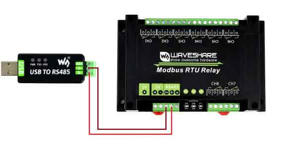
Answer:Not supported, RS232,RS485 and TTL can not be interchangeable, support USB to RS232,RS485 or TTL.Answer:TTL and RS232 are full-duplex communication, you can short RXD and TXD to test, RS485 is half-duplex communication, you can test with an external USB to RS485 device, the following figure is the loopback test TTL: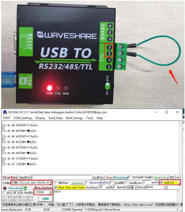
- Answer:VCC is the power supply pin, which can be switched by 5V or 3.3V (50mA) to power the connected device, if the device already has another external power supply, it can be connected without VCC.
- Connects Modbus POE ETH Relay to the LAN via a network cable, powered through the power port or via POE.

