- sales/support
Google Chat:---
- sales
+86-0755-88291180
- sales01
sales@spotpear.com
- sales02
dragon_manager@163.com
- support
tech-support@spotpear.com
- CEO-Complaints
zhoujie@spotpear.com
- Only Tech-Support
WhatsApp:13246739196
- Purchase/Shipping/Refund
WhatsApp:13424403025
Raspberry Pi 1.14inch 1.3inch LCD - Python Usage
- If you have previously installed the Kernel Driver with the PiTFT Easy Setup, you will need to remove it first in order to run this example.
Now that you have everything setup, we're going to look over three different examples. For the first, we'll take a look at automatically scaling and cropping an image and then centering it on the display.
Turning on the Backlight
On some displays, the backlight is controlled by a separate pin such as the 1.3" TFT Bonnet with Joystick. On such displays, running the below code will likely result in the display remaining black. To turn on the backlight, you will need to add a small snippet of code. If your backlight pin number differs, be sure to change it in the code:
- # Turn on the Backlight
- backlight = DigitalInOut(board.D26)
- backlight.switch_to_output()
- backlight.value = True
Displaying an Image
Here's the full code to the example. We will go through it section by section to help you better understand what is going on. Let's start by downloading an image of Blinka. This image has enough border to allow resizing and cropping with a variety of display sizes and rations to still look good.
Make sure you save it as blinka.jpg and place it in the same folder as your script. Here's the code we'll be loading onto the Raspberry Pi. We'll go over the interesting parts.
- """
- Be sure to check the learn guides for more usage information.
- This example is for use on (Linux) computers that are using CPython with
- Adafruit Blinka to support CircuitPython libraries. CircuitPython does
- not support PIL/pillow (python imaging library)!
- Author(s): Melissa LeBlanc-Williams for Adafruit Industries
- """
- import digitalio
- import board
- from PIL import Image, ImageDraw
- import adafruit_rgb_display.ili9341 as ili9341
- import adafruit_rgb_display.st7789 as st7789 # pylint: disable=unused-import
- import adafruit_rgb_display.hx8357 as hx8357 # pylint: disable=unused-import
- import adafruit_rgb_display.st7735 as st7735 # pylint: disable=unused-import
- import adafruit_rgb_display.ssd1351 as ssd1351 # pylint: disable=unused-import
- import adafruit_rgb_display.ssd1331 as ssd1331 # pylint: disable=unused-import
- # Configuration for CS and DC pins (these are PiTFT defaults):
- cs_pin = digitalio.DigitalInOut(board.CE0)
- dc_pin = digitalio.DigitalInOut(board.D25)
- reset_pin = digitalio.DigitalInOut(board.D24)
- # Config for display baudrate (default max is 24mhz):
- BAUDRATE = 24000000
- # Setup SPI bus using hardware SPI:
- spi = board.SPI()
- # pylint: disable=line-too-long
- # Create the display:
- # disp = st7789.ST7789(spi, rotation=90, # 2.0" ST7789
- # disp = st7789.ST7789(spi, height=240, y_offset=80, rotation=180, # 1.3", 1.54" ST7789
- # disp = st7789.ST7789(spi, rotation=90, width=135, height=240, x_offset=53, y_offset=40, # 1.14" ST7789
- # disp = hx8357.HX8357(spi, rotation=180, # 3.5" HX8357
- # disp = st7735.ST7735R(spi, rotation=90, # 1.8" ST7735R
- # disp = st7735.ST7735R(spi, rotation=270, height=128, x_offset=2, y_offset=3, # 1.44" ST7735R
- # disp = st7735.ST7735R(spi, rotation=90, bgr=True, # 0.96" MiniTFT ST7735R
- # disp = ssd1351.SSD1351(spi, rotation=180, # 1.5" SSD1351
- # disp = ssd1351.SSD1351(spi, height=96, y_offset=32, rotation=180, # 1.27" SSD1351
- # disp = ssd1331.SSD1331(spi, rotation=180, # 0.96" SSD1331
- disp = ili9341.ILI9341(
- spi,
- rotation=90, # 2.2", 2.4", 2.8", 3.2" ILI9341
- cs=cs_pin,
- dc=dc_pin,
- rst=reset_pin,
- baudrate=BAUDRATE,
- )
- # pylint: enable=line-too-long
- # Create blank image for drawing.
- # Make sure to create image with mode 'RGB' for full color.
- if disp.rotation % 180 == 90:
- height = disp.width # we swap height/width to rotate it to landscape!
- width = disp.height
- else:
- width = disp.width # we swap height/width to rotate it to landscape!
- height = disp.height
- image = Image.new("RGB", (width, height))
- # Get drawing object to draw on image.
- draw = ImageDraw.Draw(image)
- # Draw a black filled box to clear the image.
- draw.rectangle((0, 0, width, height), outline=0, fill=(0, 0, 0))
- disp.image(image)
- image = Image.open("blinka.jpg")
- # Scale the image to the smaller screen dimension
- image_ratio = image.width / image.height
- screen_ratio = width / height
- if screen_ratio < image_ratio:
- scaled_width = image.width * height // image.height
- scaled_height = height
- else:
- scaled_width = width
- scaled_height = image.height * width // image.width
- image = image.resize((scaled_width, scaled_height), Image.BICUBIC)
- # Crop and center the image
- x = scaled_width // 2 - width // 2
- y = scaled_height // 2 - height // 2
- image = image.crop((x, y, x + width, y + height))
- # Display image.
- disp.image(image)
So we start with our usual imports including a couple of Pillow modules and the display drivers. That is followed by defining a few pins here. The reason we chose these is because they allow you to use the same code with the PiTFT if you chose to do so.
- import digitalio
- import board
- from PIL import Image, ImageDraw
- import adafruit_rgb_display.ili9341 as ili9341
- import adafruit_rgb_display.st7789 as st7789
- import adafruit_rgb_display.hx8357 as hx8357
- import adafruit_rgb_display.st7735 as st7735
- import adafruit_rgb_display.ssd1351 as ssd1351
- import adafruit_rgb_display.ssd1331 as ssd1331
- # Configuration for CS and DC pins
- cs_pin = digitalio.DigitalInOut(board.CE0)
- dc_pin = digitalio.DigitalInOut(board.D25)
- reset_pin = digitalio.DigitalInOut(board.D24)
Next we'll set the baud rate from the default 24 MHz so that it works on a variety of displays. The exception to this is the SSD1351 driver, which will automatically limit it to 16MHz even if you pass 24MHz. We'll set up out SPI bus and then initialize the display.
We wanted to make these examples work on as many displays as possible with very few changes. The ILI9341 display is selected by default. For other displays, go ahead and comment out the line that starts with:
disp = ili9341.ILI9341(spi,
and uncomment the line appropriate for your display. The displays have a rotation property so that it can be set in just one place.
- # Config for display baudrate (default max is 24mhz):
- BAUDRATE = 24000000
- # Setup SPI bus using hardware SPI:
- spi = board.SPI()
- #disp = st7789.ST7789(spi, rotation=90, # 2.0" ST7789
- #disp = st7789.ST7789(spi, height=240, y_offset=80, rotation=180, # 1.3", 1.54" ST7789
- #disp = st7789.ST7789(spi, rotation=90, width=135, height=240, x_offset=53, y_offset=40, # 1.14" ST7789
- #disp = hx8357.HX8357(spi, rotation=180, # 3.5" HX8357
- #disp = st7735.ST7735R(spi, rotation=90, # 1.8" ST7735R
- #disp = st7735.ST7735R(spi, rotation=270, height=128, x_offset=2, y_offset=3, # 1.44" ST7735R
- #disp = st7735.ST7735R(spi, rotation=90, bgr=True, # 0.96" MiniTFT ST7735R
- #disp = ssd1351.SSD1351(spi, rotation=180, # 1.5" SSD1351
- #disp = ssd1351.SSD1351(spi, height=96, y_offset=32, rotation=180, # 1.27" SSD1351
- #disp = ssd1331.SSD1331(spi, rotation=180, # 0.96" SSD1331
- disp = ili9341.ILI9341(spi, rotation=90, # 2.2", 2.4", 2.8", 3.2" ILI9341
- cs=cs_pin, dc=dc_pin, rst=reset_pin, baudrate=BAUDRATE)
Next we read the current rotation setting of the display and if it is 90 or 270 degrees, we need to swap the width and height for our calculations, otherwise we just grab the width and height. We will create an image with our dimensions and use that to create a draw object. The draw object will have all of our drawing functions.
- # Create blank image for drawing.
- # Make sure to create image with mode 'RGB' for full color.
- if disp.rotation % 180 == 90:
- height = disp.width # we swap height/width to rotate it to landscape!
- width = disp.height
- else:
- width = disp.width # we swap height/width to rotate it to landscape!
- height = disp.height
- image = Image.new('RGB', (width, height))
- # Get drawing object to draw on image.
- draw = ImageDraw.Draw(image)
Next we clear whatever is on the screen by drawing a black rectangle. This isn't strictly necessary since it will be overwritten by the image, but it kind of sets the stage.
- # Draw a black filled box to clear the image.
- draw.rectangle((0, 0, width, height), outline=0, fill=(0, 0, 0))
- disp.image(image)
Next we open the Blinka image, which we've named blinka.jpg, which assumes it is in the same directory that you are running the script from. Feel free to change it if it doesn't match your configuration.
- image = Image.open("blinka.jpg")
Here's where it starts to get interesting. We want to scale the image so that it matches either the width or height of the display, depending on which is smaller, so that we have some of the image to chop off when we crop it. So we start by calculating the width to height ration of both the display and the image. If the height is the closer of the dimensions, we want to match the image height to the display height and let it be a bit wider than the display. Otherwise, we want to do the opposite.
Once we've figured out how we're going to scale it, we pass in the new dimensions and using a Bicubic rescaling method, we reassign the newly rescaled image back to image. Pillow has quite a few different methods to choose from, but Bicubic does a great job and is reasonably fast.
- # Scale the image to the smaller screen dimension
- image_ratio = image.width / image.height
- screen_ratio = width / height
- if screen_ratio < image_ratio:
- scaled_width = image.width * height // image.height
- scaled_height = height
- else:
- scaled_width = width
- scaled_height = image.height * width // image.width
- image = image.resize((scaled_width, scaled_height), Image.BICUBIC)
Next we want to figure the starting x and y points of the image where we want to begin cropping it so that it ends up centered. We do that by using a standard centering function, which is basically requesting the difference of the center of the display and the center of the image. Just like with scaling, we replace the image variable with the newly cropped image.
- # Crop and center the image
- x = scaled_width // 2 - width // 2
- y = scaled_height // 2 - height // 2
- image = image.crop((x, y, x + width, y + height))
Finally, we take our image and display it. At this point, the image should have the exact same dimensions at the display and fill it completely.
- disp.image(image)

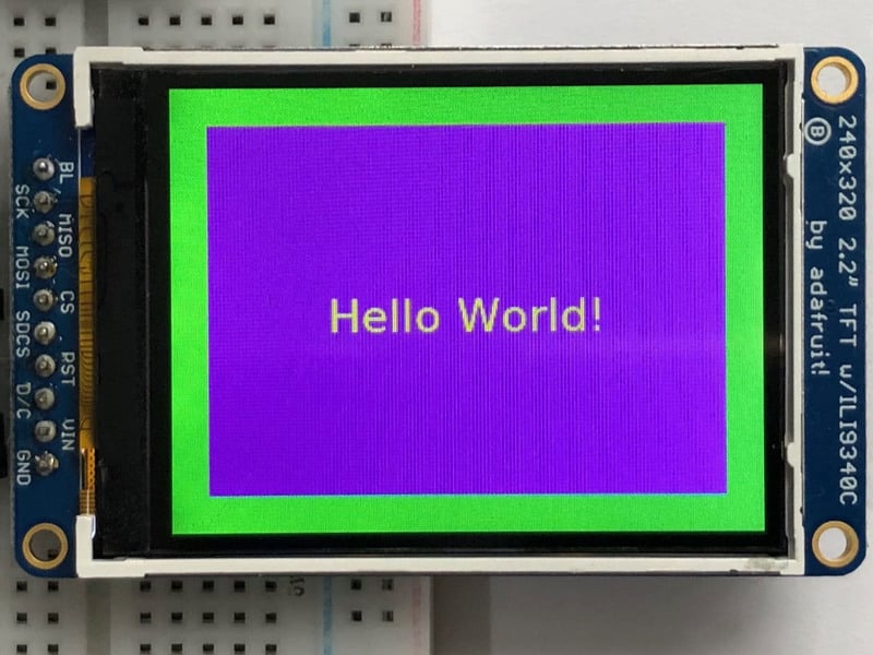
Drawing Shapes and Text
In the next example, we'll take a look at drawing shapes and text. This is very similar to the displayio example, but it uses Pillow instead. Here's the code for that.
- """
- This demo will draw a few rectangles onto the screen along with some text
- on top of that.
- This example is for use on (Linux) computers that are using CPython with
- Adafruit Blinka to support CircuitPython libraries. CircuitPython does
- not support PIL/pillow (python imaging library)!
- Author(s): Melissa LeBlanc-Williams for Adafruit Industries
- """
- import digitalio
- import board
- from PIL import Image, ImageDraw, ImageFont
- import adafruit_rgb_display.ili9341 as ili9341
- import adafruit_rgb_display.st7789 as st7789 # pylint: disable=unused-import
- import adafruit_rgb_display.hx8357 as hx8357 # pylint: disable=unused-import
- import adafruit_rgb_display.st7735 as st7735 # pylint: disable=unused-import
- import adafruit_rgb_display.ssd1351 as ssd1351 # pylint: disable=unused-import
- import adafruit_rgb_display.ssd1331 as ssd1331 # pylint: disable=unused-import
- # First define some constants to allow easy resizing of shapes.
- BORDER = 20
- FONTSIZE = 24
- # Configuration for CS and DC pins (these are PiTFT defaults):
- cs_pin = digitalio.DigitalInOut(board.CE0)
- dc_pin = digitalio.DigitalInOut(board.D25)
- reset_pin = digitalio.DigitalInOut(board.D24)
- # Config for display baudrate (default max is 24mhz):
- BAUDRATE = 24000000
- # Setup SPI bus using hardware SPI:
- spi = board.SPI()
- # pylint: disable=line-too-long
- # Create the display:
- # disp = st7789.ST7789(spi, rotation=90, # 2.0" ST7789
- # disp = st7789.ST7789(spi, height=240, y_offset=80, rotation=180, # 1.3", 1.54" ST7789
- # disp = st7789.ST7789(spi, rotation=90, width=135, height=240, x_offset=53, y_offset=40, # 1.14" ST7789
- # disp = hx8357.HX8357(spi, rotation=180, # 3.5" HX8357
- # disp = st7735.ST7735R(spi, rotation=90, # 1.8" ST7735R
- # disp = st7735.ST7735R(spi, rotation=270, height=128, x_offset=2, y_offset=3, # 1.44" ST7735R
- # disp = st7735.ST7735R(spi, rotation=90, bgr=True, # 0.96" MiniTFT ST7735R
- # disp = ssd1351.SSD1351(spi, rotation=180, # 1.5" SSD1351
- # disp = ssd1351.SSD1351(spi, height=96, y_offset=32, rotation=180, # 1.27" SSD1351
- # disp = ssd1331.SSD1331(spi, rotation=180, # 0.96" SSD1331
- disp = ili9341.ILI9341(
- spi,
- rotation=90, # 2.2", 2.4", 2.8", 3.2" ILI9341
- cs=cs_pin,
- dc=dc_pin,
- rst=reset_pin,
- baudrate=BAUDRATE,
- )
- # pylint: enable=line-too-long
- # Create blank image for drawing.
- # Make sure to create image with mode 'RGB' for full color.
- if disp.rotation % 180 == 90:
- height = disp.width # we swap height/width to rotate it to landscape!
- width = disp.height
- else:
- width = disp.width # we swap height/width to rotate it to landscape!
- height = disp.height
- image = Image.new("RGB", (width, height))
- # Get drawing object to draw on image.
- draw = ImageDraw.Draw(image)
- # Draw a green filled box as the background
- draw.rectangle((0, 0, width, height), fill=(0, 255, 0))
- disp.image(image)
- # Draw a smaller inner purple rectangle
- draw.rectangle(
- (BORDER, BORDER, width - BORDER - 1, height - BORDER - 1), fill=(170, 0, 136)
- )
- # Load a TTF Font
- font = ImageFont.truetype("/usr/share/fonts/truetype/dejavu/DejaVuSans.ttf", FONTSIZE)
- # Draw Some Text
- text = "Hello World!"
- (font_width, font_height) = font.getsize(text)
- draw.text(
- (width // 2 - font_width // 2, height // 2 - font_height // 2),
- text,
- font=font,
- fill=(255, 255, 0),
- )
- # Display image.
- disp.image(image)
Just like in the last example, we'll do our imports, but this time we're including the ImageFont Pillow module because we'll be drawing some text this time.
- import digitalio
- import board
- from PIL import Image, ImageDraw, ImageFont
- import adafruit_rgb_display.ili9341 as ili9341
Next we'll define some parameters that we can tweak for various displays. The BORDER will be the size in pixels of the green border between the edge of the display and the inner purple rectangle. The FONTSIZE will be the size of the font in points so that we can adjust it easily for different displays.
- BORDER = 20
- FONTSIZE = 24
Next, just like in the previous example, we will set up the display, setup the rotation, and create a draw object. If you have are using a different display than the ILI9341, go ahead and adjust your initializer as explained in the previous example. After that, we will setup the background with a green rectangle that takes up the full screen. To get green, we pass in a tuple that has our Red, Green, and Blue color values in it in that order which can be any integer from 0 to 255.
- draw.rectangle((0, 0, width, height), fill=(0, 255, 0))
- disp.image(image)
Next we will draw an inner purple rectangle. This is the same color value as our example in displayio quickstart, except the hexadecimal values have been converted to decimal. We use the BORDER parameter to calculate the size and position that we want to draw the rectangle.
- draw.rectangle((BORDER, BORDER, width - BORDER - 1, height - BORDER - 1),
- fill=(170, 0, 136))
Next we'll load a TTF font. The DejaVuSans.ttf font should come preloaded on your Pi in the location in the code. We also make use of the FONTSIZE parameter that we discussed earlier.
- # Load a TTF Font
- font = ImageFont.truetype('/usr/share/fonts/truetype/dejavu/DejaVuSans.ttf', FONTSIZE)
Now we draw the text Hello World onto the center of the display. You may recognize the centering calculation was the same one we used to center crop the image in the previous example. In this example though, we get the font size values using the getsize() function of the font object.
- # Draw Some Text
- text = "Hello World!"
- (font_width, font_height) = font.getsize(text)
- draw.text((width//2 - font_width//2, height//2 - font_height//2),
- text, font=font, fill=(255, 255, 0))
Finally, just like before, we display the image.
- disp.image(image)
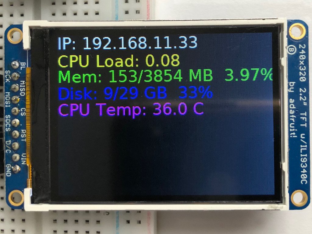
Displaying System Information
In this last example we'll take a look at getting the system information and displaying it. This can be very handy for system monitoring. Here's the code for that example:
- """
- This will show some Linux Statistics on the attached display. Be sure to adjust
- to the display you have connected. Be sure to check the learn guides for more
- usage information.
- This example is for use on (Linux) computers that are using CPython with
- Adafruit Blinka to support CircuitPython libraries. CircuitPython does
- not support PIL/pillow (python imaging library)!
- """
- import time
- import subprocess
- import digitalio
- import board
- from PIL import Image, ImageDraw, ImageFont
- import adafruit_rgb_display.ili9341 as ili9341
- import adafruit_rgb_display.st7789 as st7789 # pylint: disable=unused-import
- import adafruit_rgb_display.hx8357 as hx8357 # pylint: disable=unused-import
- import adafruit_rgb_display.st7735 as st7735 # pylint: disable=unused-import
- import adafruit_rgb_display.ssd1351 as ssd1351 # pylint: disable=unused-import
- import adafruit_rgb_display.ssd1331 as ssd1331 # pylint: disable=unused-import
- # Configuration for CS and DC pins (these are PiTFT defaults):
- cs_pin = digitalio.DigitalInOut(board.CE0)
- dc_pin = digitalio.DigitalInOut(board.D25)
- reset_pin = digitalio.DigitalInOut(board.D24)
- # Config for display baudrate (default max is 24mhz):
- BAUDRATE = 24000000
- # Setup SPI bus using hardware SPI:
- spi = board.SPI()
- # pylint: disable=line-too-long
- # Create the display:
- # disp = st7789.ST7789(spi, rotation=90, # 2.0" ST7789
- # disp = st7789.ST7789(spi, height=240, y_offset=80, rotation=180, # 1.3", 1.54" ST7789
- # disp = st7789.ST7789(spi, rotation=90, width=135, height=240, x_offset=53, y_offset=40, # 1.14" ST7789
- # disp = hx8357.HX8357(spi, rotation=180, # 3.5" HX8357
- # disp = st7735.ST7735R(spi, rotation=90, # 1.8" ST7735R
- # disp = st7735.ST7735R(spi, rotation=270, height=128, x_offset=2, y_offset=3, # 1.44" ST7735R
- # disp = st7735.ST7735R(spi, rotation=90, bgr=True, # 0.96" MiniTFT ST7735R
- # disp = ssd1351.SSD1351(spi, rotation=180, # 1.5" SSD1351
- # disp = ssd1351.SSD1351(spi, height=96, y_offset=32, rotation=180, # 1.27" SSD1351
- # disp = ssd1331.SSD1331(spi, rotation=180, # 0.96" SSD1331
- disp = ili9341.ILI9341(
- spi,
- rotation=90, # 2.2", 2.4", 2.8", 3.2" ILI9341
- cs=cs_pin,
- dc=dc_pin,
- rst=reset_pin,
- baudrate=BAUDRATE,
- )
- # pylint: enable=line-too-long
- # Create blank image for drawing.
- # Make sure to create image with mode 'RGB' for full color.
- if disp.rotation % 180 == 90:
- height = disp.width # we swap height/width to rotate it to landscape!
- width = disp.height
- else:
- width = disp.width # we swap height/width to rotate it to landscape!
- height = disp.height
- image = Image.new("RGB", (width, height))
- # Get drawing object to draw on image.
- draw = ImageDraw.Draw(image)
- # Draw a black filled box to clear the image.
- draw.rectangle((0, 0, width, height), outline=0, fill=(0, 0, 0))
- disp.image(image)
- # First define some constants to allow easy positioning of text.
- padding = -2
- x = 0
- # Load a TTF font. Make sure the .ttf font file is in the
- # same directory as the python script!
- # Some other nice fonts to try: http://www.dafont.com/bitmap.php
- font = ImageFont.truetype("/usr/share/fonts/truetype/dejavu/DejaVuSans.ttf", 24)
- while True:
- # Draw a black filled box to clear the image.
- draw.rectangle((0, 0, width, height), outline=0, fill=0)
- # Shell scripts for system monitoring from here:
- # https://unix.stackexchange.com/questions/119126/command-to-display-memory-usage-disk-usage-and-cpu-load
- cmd = "hostname -I | cut -d' ' -f1"
- IP = "IP: " + subprocess.check_output(cmd, shell=True).decode("utf-8")
- cmd = "top -bn1 | grep load | awk '{printf \"CPU Load: %.2f\", $(NF-2)}'"
- CPU = subprocess.check_output(cmd, shell=True).decode("utf-8")
- cmd = "free -m | awk 'NR==2{printf \"Mem: %s/%s MB %.2f%%\", $3,$2,$3*100/$2 }'"
- MemUsage = subprocess.check_output(cmd, shell=True).decode("utf-8")
- cmd = 'df -h | awk \'$NF=="/"{printf "Disk: %d/%d GB %s", $3,$2,$5}\''
- Disk = subprocess.check_output(cmd, shell=True).decode("utf-8")
- cmd = "cat /sys/class/thermal/thermal_zone0/temp | awk '{printf \"CPU Temp: %.1f C\", $(NF-0) / 1000}'" # pylint: disable=line-too-long
- Temp = subprocess.check_output(cmd, shell=True).decode("utf-8")
- # Write four lines of text.
- y = padding
- draw.text((x, y), IP, font=font, fill="#FFFFFF")
- y += font.getsize(IP)[1]
- draw.text((x, y), CPU, font=font, fill="#FFFF00")
- y += font.getsize(CPU)[1]
- draw.text((x, y), MemUsage, font=font, fill="#00FF00")
- y += font.getsize(MemUsage)[1]
- draw.text((x, y), Disk, font=font, fill="#0000FF")
- y += font.getsize(Disk)[1]
- draw.text((x, y), Temp, font=font, fill="#FF00FF")
- # Display image.
- disp.image(image)
- time.sleep(0.1)
Just like the last example, we'll start by importing everything we imported, but we're adding two more imports. The first one is time so that we can add a small delay and the other is subprocess so we can gather some system information.
- import time
- import subprocess
- import digitalio
- import board
- from PIL import Image, ImageDraw, ImageFont
- import adafruit_rgb_display.ili9341 as ili9341
Next, just like in the first two examples, we will set up the display, setup the rotation, and create a draw object. If you have are using a different display than the ILI9341, go ahead and adjust your initializer as explained in the previous example.
Just like in the first example, we're going to draw a black rectangle to fill up the screen. After that, we're going to set up a couple of constants to help with positioning text. The first is the padding and that will be the Y-position of the top-most text and the other is x which is the X-Position and represents the left side of the text.
- # First define some constants to allow easy positioning of text.
- padding = -2
- x = 0
Next, we load a font just like in the second example.
- font = ImageFont.truetype('/usr/share/fonts/truetype/dejavu/DejaVuSans.ttf', 24)
Now we get to the main loop and by using while True:, it will loop until Control+C is pressed on the keyboard. The first item inside here, we clear the screen, but notice that instead of giving it a tuple like before, we can just pass 0 and it will draw black.
- draw.rectangle((0, 0, width, height), outline=0, fill=0)
Next, we run a few scripts using the subprocess function that get called to the Operating System to get information. The in each command is passed through awk in order to be formatted better for the display. By having the OS do the work, we don't have to. These little scripts came from https://unix.stackexchange.com/questions/119126/command-to-display-memory-usage-disk-usage-and-cpu-load
- cmd = "hostname -I | cut -d\' \' -f1"
- IP = "IP: "+subprocess.check_output(cmd, shell=True).decode("utf-8")
- cmd = "top -bn1 | grep load | awk '{printf \"CPU Load: %.2f\", $(NF-2)}'"
- CPU = subprocess.check_output(cmd, shell=True).decode("utf-8")
- cmd = "free -m | awk 'NR==2{printf \"Mem: %s/%s MB %.2f%%\", $3,$2,$3*100/$2 }'"
- MemUsage = subprocess.check_output(cmd, shell=True).decode("utf-8")
- cmd = "df -h | awk '$NF==\"/\"{printf \"Disk: %d/%d GB %s\", $3,$2,$5}'"
- Disk = subprocess.check_output(cmd, shell=True).decode("utf-8")
- cmd = "cat /sys/class/thermal/thermal_zone0/temp | awk \'{printf \"CPU Temp: %.1f C\", $(NF-0) / 1000}\'" # pylint: disable=line-too-long
- Temp = subprocess.check_output(cmd, shell=True).decode("utf-8")
Now we display the information for the user. Here we use yet another way to pass color information. We can pass it as a color string using the pound symbol, just like we would with HTML. With each line, we take the height of the line using getsize() and move the pointer down by that much.
- y = padding
- draw.text((x, y), IP, font=font, fill="#FFFFFF")
- y += font.getsize(IP)[1]
- draw.text((x, y), CPU, font=font, fill="#FFFF00")
- y += font.getsize(CPU)[1]
- draw.text((x, y), MemUsage, font=font, fill="#00FF00")
- y += font.getsize(MemUsage)[1]
- draw.text((x, y), Disk, font=font, fill="#0000FF")
- y += font.getsize(Disk)[1]
- draw.text((x, y), Temp, font=font, fill="#FF00FF")
Finally, we write all the information out to the display using disp.image(). Since we are looping, we tell Python to sleep for 0.1 seconds so that the CPU never gets too busy.
- disp.image(image)
- time.sleep(.1)