- sales/support
Google Chat:---
- sales
+86-0755-88291180
- sales01
sales@spotpear.com
- sales02
dragon_manager@163.com
- support
tech-support@spotpear.com
- CEO-Complaints
zhoujie@spotpear.com
- Only Tech-Support
WhatsApp:13246739196
- Purchase/Shipping/Refund
WhatsApp:13424403025
Chapter 11 of KitiBot-Microbit User Guide
Chapter 11 of KitiBot-Microbit
KitiBot, after seen a high-speed rail moving fast along the track, he hopes to have same track to move along, like a high-speed train. In this chapter we will learn about the “tracing function” of kitiBot. The aim of this chapter is to learn about the tracking sensor, and how to use it to implement the robot patrolling function.
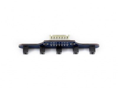
Tracking sensor: the tracking sensor helps the robot move along the black line on the ground. There are five detectors at the bottom of the sensor, and the infrared LED light is used to project infrared light to the ground to detect the deviation of the module relative to the black line.
Blocks
 The detection range of different sensors are different, so we need to calibrate sensors to get their min and max values, then calibrate original data. To use this block, you need to put the robot on center of black line, move left and right to get dozens of data for calibrating.
 Get original data (five data) from infrared tracking sensor
 Get the maximum value which every sensor able to detect after calibrating
 Get the minimum value which every sensor able to detect after calibrating
 Read the position of black line, range of data is 0~4000, 0 stands for left side, 4000 stand for right side, 2000 means center.
Section 1
This section, we read original data of tracking sensor from serial port. Let's see how will these data change.
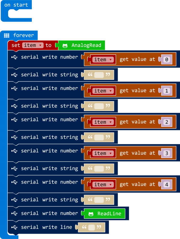
We read the data and save it to various item, then send the data to serial port.
https://cdn.static.spotpear.com/uploads/picture/learn/micro-bit/micro-bit-kit/chapter-11-of-kitibot-microbit/chapter-11-of-kitibot-microbit-07.gif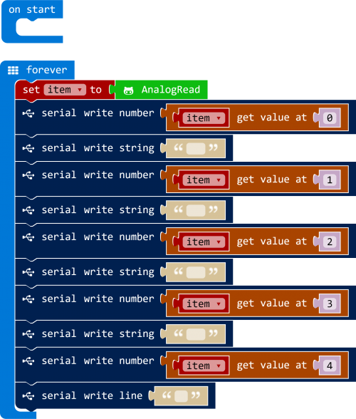
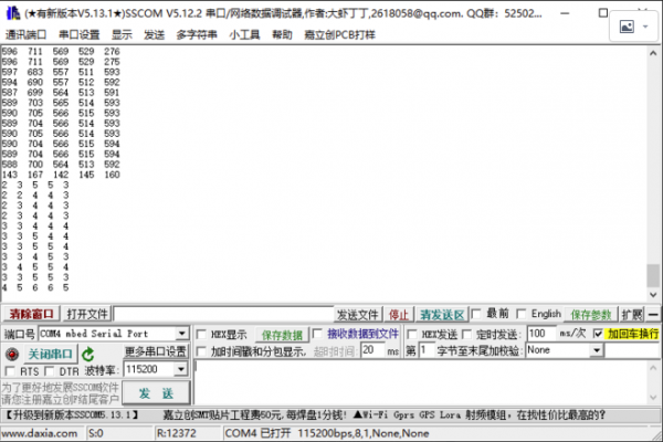
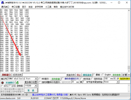
Connect the micro:bit to PC, and search the COM port on Device Mangaer. Download the code to micro:bit. Open serial assistant software, set baudrate to 115200. Five data will be printed to software. If you higher the robot, the data will turn small to about 0~10. If you put the robot to white ground, the data will rise to 500~700, on black line, the output are about 100.
Section 2
We let the script to output the position of black line base on previous section
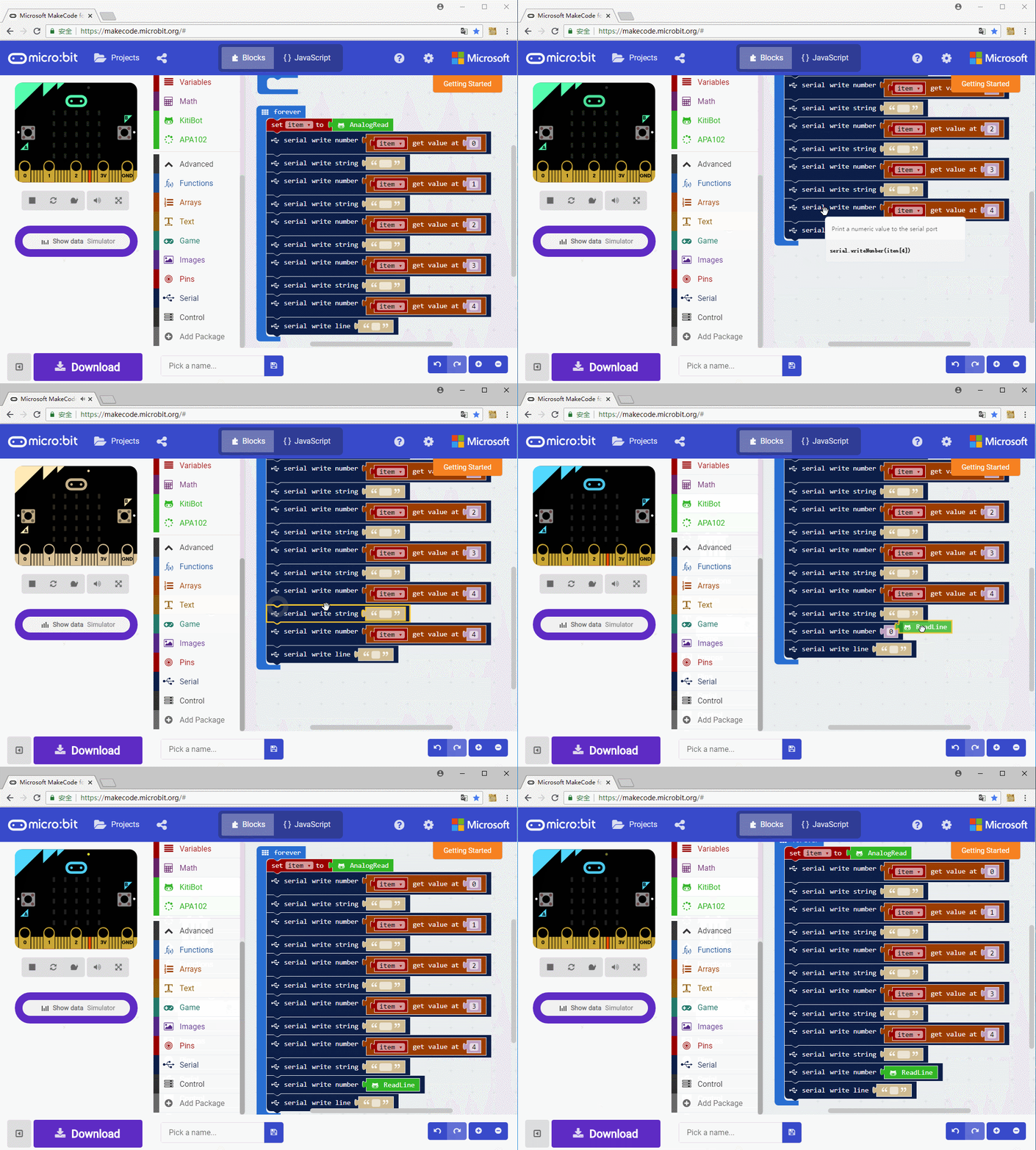
Download the code to micr:bit, you can see that data are output as below. When black line is under tracking sensor, the data are smaller, about 80~10. The right data is the position of black line. Note that these data are not be calibrated.
Section 3
We calibrate the output data in this section
https://cdn.static.spotpear.com/uploads/picture/learn/micro-bit/micro-bit-kit/chapter-11-of-kitibot-microbit/chapter-11-of-kitibot-microbit-13.gif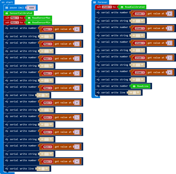
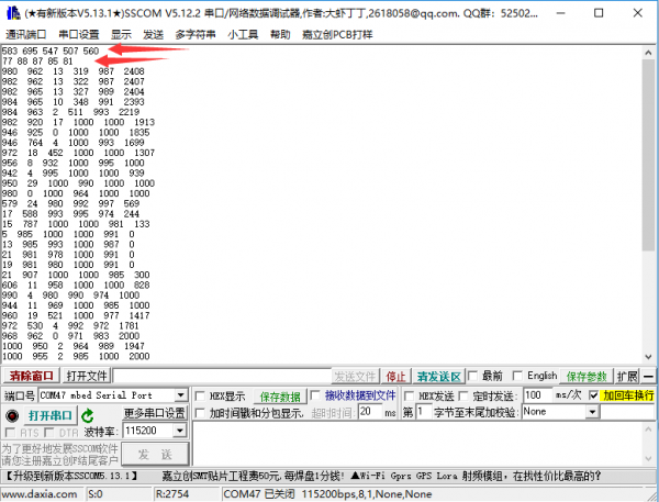
Put the robot on ground, and make sure the black lines is on the center. After 3s (run the code), robot begin to calibrate, turn left first, then turn right, finally turn back to original place. During calibrating, the min and max values of every sensor will be printed, and data calibrated.
Section 4
In previous sections we learned about how to read the data of tracking sensor, here let's make robot to move along the black line. That is make robot turn right to back to black line when the data show that black line is on the right by slowing down the right motor, and turn left if the black line is on the left by slowing down the left motor.
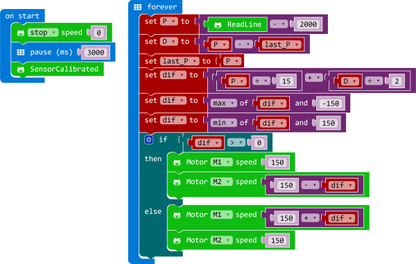
The P on the code is position tolerance, if it is positive, means robot deviation to right, and robot deviation to left if it is negative.
D is the difference between current P and last P, bigger the D, faster the robot response.
dif is the value which motor need to change, this value is based on P and D