


- sales/support
Google Chat: zj734465502@gmail.com
- sales
+86-0755-88291180
- sales01
sales01@spotpear.com
- sales02
dragon_manager@163.com
- support
services01@spotpear.com
- CEO-Complaints
manager01@spotpear.com
- sales/support
WhatsApp:13246739196
Raspberry Pi PICO RP2040-PiZero User Guide
Code
Schematic diagram
Introduction
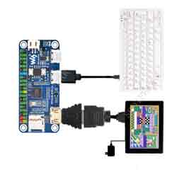
RP2040-PiZero is a high-performance and cost-effective microcontroller board designed by Waveshare, onboard DVI interface, TF card slot and PIO-USB port, compatible with Raspberry Pi 40PIN GPIO header, easy to develop and integrate into the products.
Features
- RP2040 microcontroller chip designed by Raspberry Pi in the United Kingdom
- Dual-core ARM Cortex M0+ processor, flexible clock running up to 133 MHz
- 264KB of SRAM, and 16MB of onboard Flash memory
- Onboard DVI interface can drive most HDMI screens (DVI compatibility required)
- Supports using as a USB host or slave via onboard PIO-USB port
- Onboard TF card slot for reading and writing TF card
- Onboard Lithium battery recharge/discharge header, suitable for mobile scenarios
- USB 1.1 with device and host support
- Drag-and-drop programming using mass storage over USB
- Low-power sleep and dormant modes
- 2 × SPI, 2 × I2C, 2 × UART, 4 × 12-bit ADC, 16 × controllable PWM channels
- Accurate clock and timer on-chip
- Temperature sensor
- Accelerated floating-point libraries on-chip
- 8 × Programmable I/O (PIO) state machines for custom peripheral support
Pico Quick Start
Download Firmware
- MicroPython Firmware Download

- C_Blink Firmware Download

MicroPython Series
- 【MicroPython】 machine.Pin Function
- 【MicroPython】 machine.PWM Function
- 【MicroPython】 machine.ADC Function
- 【MicroPython】 machine.UART Function
- 【MicroPython】 machine.I2C Function
- 【MicroPython】 machine.SPI Function
- 【MicroPython】 rp2.StateMachine
C/C++ Series
Arduino IDE
Installieren Arduino IDE
- Download the installation package of Arduino IDE from Arduino official website.
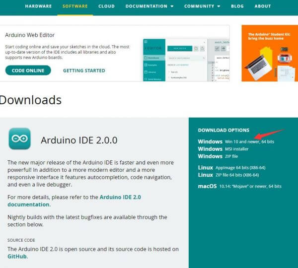
- Select Just download.
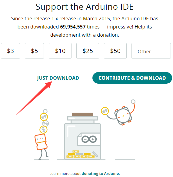
- After downloading, click Install.
Note: During the installation process, you will be prompted to install the driver. We can click on Install to proceed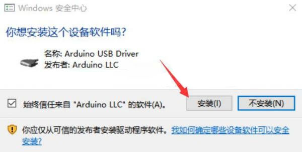
Installing Arduino Pico Core in the Arduino IDE
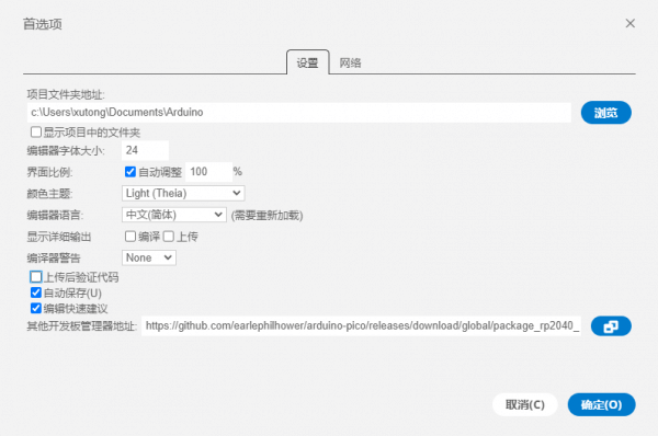
- Arduino IDE, click the file in the upper left corner, and select preferences.
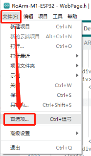
- Add the following link to the URL of the additional development board manager, and then click OK.
https://github.com/earlephilhower/arduino-pico/releases/download/global/package_rp2040_index.json
Note: If you already have an ESP32 board URL, you can separate the URLs with commas, as shown below:https://dl.espressif.com/dl/package_esp32_index.json,https://github.com/earlephilhower/arduino-pico/releases/download/global/package_rp2040_index.json
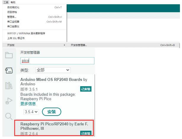
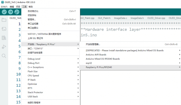
- Click tools > development board > development board manager > search pico, because my computer has been installed, it shows that it is installed.
First upload program
- Press and hold the BOOTSET button on the Pico board, connect the Pico to the USB interface of the computer through a Micro USB cable, and wait for the computer to recognize a removable hard drive (RPI-RP2) before releasing the button.
- Download the program and open D1-LED.ino under arduino\PWM\D1-LED path.
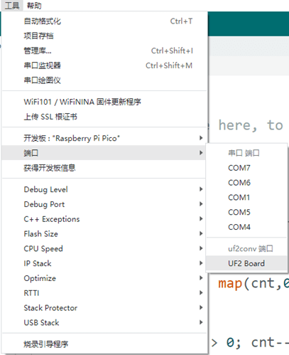
- Click on Tools>Port, remember the existing COM, there is no need to click on this COM (different computers display different COM, remember the existing COM on your own computer)
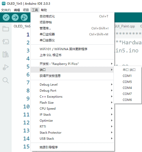
- Connect the driver board to the computer using a USB cable, then click Tools>Port, and select uf2 Board for the first connection. After uploading, connecting again will result in an additional COM port
- Click tools > development board >Raspberry Pi Pico/RP2040>Raspberry Pi Pico
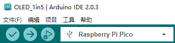
- After setting, click the right arrow to upload the program.
C routine
01-DVI
- Routine is modified based on Wren6991 PicoDVI.
Main directory analysis
- Apps directory: routine source code
- Assets directory: original images and image header files
- Include directory: default pin configuration header file
- Libdvi directory: about DVI driver source code
- Libgui directory: about GUI source code
Hello DVI routine description
- The Hello DVI routine is located in the Hello directory in the apps directory_ Under the dvi file
- In 640x480p 60Hz DVI mode, scroll to display a test image with a resolution of 320x240p RGB565.
Gui Demo routine description
- The gui demo routine is located in the gui demo file in the apps directory
- In 640x480p 60Hz DVI mode, brush white, red, yellow, green, cyan, blue, purple, and black in sequence, and then brush GUI images
02-USB
- Routine is modified based on sekigon-gonnoc的Pico-PIO-USB
Main directory analysis
- examples:Routine source code
- src:About PIO-USB driver source code
capture_hid_report Routine description
- Capture_ Hid_ The report routine is located in the capture directory under the examples directory_ Hid_ Report
- PIO-USB will serve as a USB host example program for printing HID reports received from devices.
usb_device Routine description
- USB_ The device routine is located in the USB directory under the examples directory_ Device
PIO-USB will simulate a mouse and move the mouse cursor every 0.5 seconds
Host_hid_to_device_cdc Routine description
- Host_ Hid_ To_ Device_ The cdc routine is located in the Host directory under the examples directory_ Hid_ To_ Device_ Cdc
Host_ Hid_ To_ Device_ Cdc is similar to capture_ Hid_ Report, print mouse/keyboard reports from the host port to the device port's cdc.
03-MicroSD
Main directory analysis
- Tests: source code used for testing
- FatFs_ SPI: MicroSD related driver source code
Routine description
- Use terminal tools such as putty or mobaxterm to open the USB serial port corresponding to RP2040 PiZero
- Enter and the following information will be displayed
>
- Enter the help command to get the available commands, as follows
setrtc <DD> <MM> <YY> <hh> <mm> <ss>:
  Set Real Time Clock
  Parameters: new date (DD MM YY) new time in 24-hour format (hh mm ss)
	e.g.:setrtc 16 3 21 0 4 0

date:
 Print current date and time

lliot <drive#>:
 !DESTRUCTIVE! Low Level I/O Driver Test
	e.g.: lliot 1

format [<drive#:>]:
  Creates an FAT/exFAT volume on the logical drive.
	e.g.: format 0:

mount [<drive#:>]:
  Register the work area of the volume
	e.g.: mount 0:

unmount <drive#:>:
  Unregister the work area of the volume

chdrive <drive#:>:
  Changes the current directory of the logical drive.
  <path> Specifies the directory to be set as current directory.
	e.g.: chdrive 1:

getfree [<drive#:>]:
  Print the free space on drive

cd <path>:
  Changes the current directory of the logical drive.
  <path> Specifies the directory to be set as current directory.
	e.g.: cd 1:/dir1

mkdir <path>:
  Make a new directory.
  <path> Specifies the name of the directory to be created.
	e.g.: mkdir /dir1

ls:
  List directory

cat <filename>:
  Type file contents

simple:
  Run simple FS tests

big_file_test <pathname> <size in bytes> <seed>:
 Writes random data to file <pathname>.
 <size in bytes> must be multiple of 512.
	e.g.: big_file_test bf 1048576 1
	or: big_file_test big3G-3 0xC0000000 3

cdef:
  Create Disk and Example Files
  Expects card to be already formatted and mounted

start_logger:
  Start Data Log Demo

stop_logger:
  Stop Data Log Demo
Arduino Demo
01-DVI
- This demo is based on the modification of Wren6991 PicoDVI.
Hello Dvi
- The Hello DVI demo is located in the "Hello DVI" directory.
- Scrolling display of a test image with a resolution of 320x240p in RGB565 format is in a 640x480p 60Hz DVI mode.
02-USB
- This demo is based on the modification of sekigon-gonnoc Pico-PIO-USB.
device_in
- The device_in demo is located in the "device_in" directory.
- The PIO-USB will be used as a USB host example demo for printing HID reports received from the device.
Core1 setup to run TinyUSB host with pio-usb
Device attached, address = 1
Device 1: ID 05ac:0256
Device Descriptor:
  bLength             18
  bDescriptorType     1
  bcdUSB              0110
  bDeviceClass        0
  bDeviceSubClass     0
  bDeviceProtocol     0
  bMaxPacketSize0     64
  idVendor            0x05ac
  idProduct           0x0256
  bcdDevice           0310
  iManufacturer       1     CX
  iProduct            2     2.4G Wireless Receiver
  iSerialNumber       0
  bNumConfigurations  1
TinyUSB Dual Device Info Example
03-MicroSD
Demo
- Insert the SD card and run the demo to write data to the SD card.
Hello, world!
V2-Version Card
R3/R7: 0x1aa
R3/R7: 0x40ff8000
R3/R7: 0xc0ff8000
Card Initialized: High Capacity Card
SD card initialized
SDHC/SDXC Card: hc_c_size: 30475
Sectors: 31207424
Capacity:    15238 MB
Goodbye, world!
TAG:
ESP32 desktop trinket
ESP32-S3
Raspberry Pi LCD 3D Display
Spotpear
Milk V
800x480
ESP32 LVGL
LuckFox Pico
SpotPear
Industrial Isolated Converter
Attitude Sensor
Milk-V Duo S User Guide Total
0.85inch LCD
Raspberry Pi 5 SSD
Raspberry Pi 5 Official Red-White Case
RS485 Interface
Core3566004032
ESP32-S3 ST7789
Spotpear
Metal Case
Price:
$1/9.9/10.9
Part Number:
RP2040-PiZero
Brand:
Spotpear
SKU:
0201168
TAG:
UNO R4 Minima
RP2040
Pi5
Raspberry Pi Thermal imaging
ESP32 1.54inch OLED
Raspberry Pi 5 Display Cable
Jetson Nano Fan
SpotPear
Jetson Orin NX Case
Spotpear
Raspberry Pi 5 Original Case
Raspberry Pi Thermal imaging camera
22Pin to 15Pin Cable
Raspber Pi 5 27W Power
PI5
E-Paper
CAM-GC2083
Raspberry Pi MIPI
2.66inch E-Paper E-ink G Screen Display 360x184 Red/Yellow/Black/White SPI Communication SpotPear
JETSON-NANO-MINI-Board